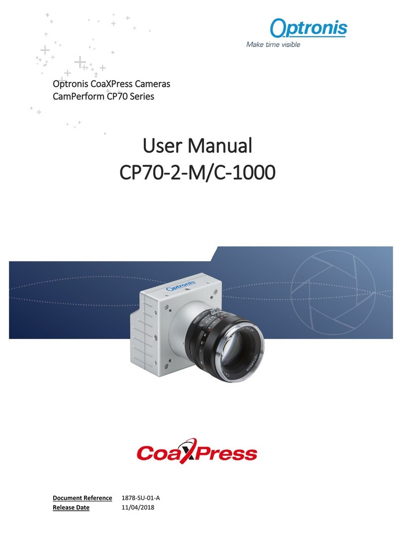
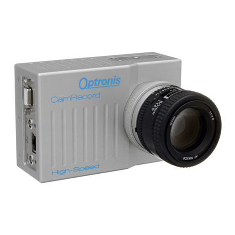
Optronis CR-S3500 User manual

CamRecord CR-S3500
User Manual
Ref. 1900-SU-02-C

CamRecord CR-S3500 Ref. 1900-SU-02-C Page 0
About this manual
Thank you for using an Optronis product.
The purpose of this document is to provide a description of Optronis CamRecord CR-S3500
camera.
Please read this manual thoroughly before operating your new camera for the first time.
Please follow all instructions and observe the warnings.
This document is subject to change without notice and corresponds to the last camera
firmwares and control software versions.
You can check product page download area to be sure you are using:
•Last manual version
•Last firmwares version. (Check Firmware Update paragraph)
•Last control software (TimeViewer) version
http://optronis.com/en/products/camrecord-cr-s3500-mc/
Support
We hope that this manual can answer your questions, but should you have any further
questions or if you wish to claim a service or warranty case, please contact your local dealer
or refer to the Optronis Support on our website or by email and please prepare following
information:
•Serial-Number: « S/N: 1902-ST-xxx ». See label at camera rear side.
•TimeViewer Software version
•Operating System (Windows 7/10/32bit/64bit …)
•Short description of the problem
Contacts
To contact us, please use below information.
Address
OPTRONIS GMBH
Ludwigstr. 2
D-77694 Kehl
Germany
Tel.: +49 (0) 78 51/91 26-0
Fax: +49 (0) 78 51/91 26-10
Website
http://optronis.com/en/
Contact Form
http://optronis.com/en/kontakt/
General Inquiries
Sales
Support

CamRecord CR-S3500 Ref. 1900-SU-02-C Page 1
Contents
Revision 4
General 5
Declaration of conformity 5
RoHS compliance 5
Scope of delivery 6
Safety Instructions 7
Typical System Configuration 8
Quick Start Instructions 10
Nikon F-Mount 10
To mount the Nikon F-Mount lens 10
To unmount the Nikon F-Mount lens 11
Nikon F-Mount for G lenses (/FMG) 12
Nikon G lenses 12
To mount the Nikon G lens 12
To unmount the Nikon G-Mount lens 13
Start of operation (Network / IP Address configuration) 14
Camera 17
Lens Interface 17
Camera Socket 17
Electrical Interface 18
Camera detailed view 18
SSD Slot 18
Power Switch 18
Programmable Output (PO) 19
Synchronization Output (SO) 19
Firmware Slot (FW) 19
GigE / USB2 Connector 19
HDMI Connector 19
Power Connector 19
SSD Slot Mounting Screw 19
Trigger Input (TI) 20
Synchronization Input (SI) 20
LED A / LED B 20
IRIG B Input 21
Serial Number 21
SSD Slot operating 22
Unmount SSD 22
Mount SSD 22
Trigger (TI) / Sync Connectors (SI / SO) details 23
External Trigger (TI) 23
External TTL 23
External Switch 23
External Synchronization Input (SI) 23
Synchronization Output (SO) 24
Power Supply 25
Minimal PC configuration 25

CamRecord CR-S3500 Ref. 1900-SU-02-C Page 2
TimeViewer Software 25
Technical Data 26
CR-S3500 26
Spectral Response (Quantum Efficiency Mono Sensor) 26
Performance (Examples) 28
CR-S3500 28
Mechanical Dimensions 29
CR Series (/FM, /FMG) 29
External Inputs 31
Trigger & Synchronization input 31
Synchronization Timing 31
Trigger Timing 31
External Outputs 32
Synchronization output 32
Synchronization Timing 32
Firmware Update 33
Why updating camera firmwares 33
How to update camera firmwares 34

CamRecord CR-S3500 Ref. 1900-SU-02-C Page 3
Table of figures
Figure 1: Typical System Configuration with Personal Computer (PC) 8
Figure 2: Typical System Configuration with Android Tablet 9
Figure 3: Overall Camera and lens view 10
Figure 4: F-lens mount 1/2 10
Figure 5: F-lens mount 2/2 11
Figure 6: F-lens unmount 11
Figure 7: FMG lens 12
Figure 8: G lens mount1/2 13
Figure 9: G lens mount 2/2, Lens locked 13
Figure 10: G-lens unmount 13
Figure 11: Camera detection 15
Figure 12: CamRecord-Sprinter Camera View 17
Figure 13: CamRecord-Sprinter camera electrical interface 18
Figure 14: SSD and its holding system 22
Figure 15: Trigger Input, schematic presentation 23
Figure 16:Synchronization Input, schematic presentation 23
Figure 17: High impedance termination 24
Figure 18: 50 Ohm termination 24
Figure 19: Spectral Response Curve 27
Figure 20: Bottom view 29
Figure 21: Side view 29
Figure 22: Top view 30
Figure 23: Front view 30
Figure 24: Input synchronization timing 31
Figure 25: Trigger timing 31
Figure 26: Output synchronization timing 32
Figure 27: TimeViewer detects an out of date camera firmware 33
Figure 28: Select files and path 35
Figure 29: Copy files to USB stick 35
Figure 30: Connected to camera 35
Figure 31: HW Update progressing 1/2 35
Figure 32: HW Update progressing 2/2 36
Figure 33: Update finished 36
Figure 34: New HW is loaded at next power cycle 36

CamRecord CR-S3500 Ref. 1900-SU-02-C Page 4
Revision
Manual revision
Date
Comments
1900-SU-02-C
28.09.2017
- Update content
1900-SU-02-B
29/03/2017
- Update layout
- Add Firmware update paragraph
1900-SU-02-A
28/02/2017
- 1st version

CamRecord CR-S3500 Ref. 1900-SU-02-C Page 5
General
Declaration of conformity
Manufacturer: Optronis GmbH
Address: Ludwigstr. 2, 77694 Kehl, Germany
We certify and declare under our sole responsibility that the following
apparatus
Product: CR-S3500
Conforms with the essential requirements of the EMC
Directive 2014/30/EU, based on the following applied
specifications:
Specifications: EN 61000-6-3 Emission
EN 61000-6-1 Immunity
Kehl, 24.02.2017
Optronis GmbH
Dr. Patrick Summ
Managing Director
RoHS compliance
CamRecord-Sprinter series cameras are Pb free manufactured.

CamRecord CR-S3500 Ref. 1900-SU-02-C Page 6
Scope of delivery
CR-S3500 CamRecord-Sprinter High-Speed camera:
Options: /C: Color sensor (Bayer Pattern)
(IR Cutoff Filter, Specification: 1830-SS-10)
/M: Monochrome sensor
/16GB: 16 GByte Memory
/256GB_SSD: 256GByte SSD for Backup
/512GB_SSD: 512GByte SSD for Backup
Lens mount: /CM: CMount
/FM: FMount
/FMG: FMount and Nikon G-Lenses
Power supply: +12Volt / 3,75Amp., 100 ... 240VAC/50-60Hz
User Manual, TimeViewer software (CD-ROM), 256GByte SSD,
WIFI Dongle, GigE cable, USB stick, SSD USB3 Docking station
Trigger / Sync BNC adapter cables

CamRecord CR-S3500 Ref. 1900-SU-02-C Page 7
Safety Instructions
•Please operate the CamRecord-Sprinter cameras from a 110 Volt to
240 Volt (50 Hz to 60 Hz A.C. frequency) power source. Other
voltage levels or frequencies may damage the camera.
•Do not orientate the optical input of the camera to direct sunlight.
•Keep the camera free protected from dirt, dust, grease and water.
•Make sure that all the connecting cables are in good condition and
that they are well mounted to their sockets.
•Please use the socket of the camera and connect it to a sufficiently
stable basis.
•Avoid strong system shocks and vibrations during transport or during
operation.
•Always unplug the camera before cleaning it. Do not use cleaning
liquids or sprays. Instead, use a dry and soft duster.
•For any further questions, please do not hesitate to contact
Optronis GmbH, especially when the camera does not work as it is
described in the user manual.

CamRecord CR-S3500 Ref. 1900-SU-02-C Page 8
Typical System Configuration
Figure 1: Typical System Configuration with Personal Computer (PC)
Power Supply CamRecord Sprinter
PC
with
GigE Interface
100 ... 240 VAC
50 ... 60 Hz
CamRecord
PC Software
(TimeViewer)
GigE (Cat6) cable

CamRecord CR-S3500 Ref. 1900-SU-02-C Page 9
Figure 2: Typical System Configuration with Android Tablet
Power Supply CamRecord Sprinter
100 ... 240 VAC
50 ... 60 Hz
CamRecord
Android App
(TimeViewer)
USB2 WI-FI dongle
Android tablet
with
WI-FI Interface

CamRecord CR-S3500 Ref. 1900-SU-02-C Page 10
Quick Start Instructions
Nikon F-Mount
Figure 3: Overall Camera and lens view
To mount the Nikon F-Mount lens
To connect properly the lens to the lens-holder, first put the lens-reference
in front of the lens-holder reference. Then, turn the lens anti-clockwise until
the silver clip (silver button) on the lens-holder locks.
Figure 4: F-lens mount 1/2
F-Mount
lens-holder
Silver clip (or silver button)
CamRecord-Sprinter camera
Lens-holder reference
Lens reference

CamRecord CR-S3500 Ref. 1900-SU-02-C Page 11
Figure 5: F-lens mount 2/2
To unmount the Nikon F-Mount lens
To unmount the lens please pull back first the silver clip (button) back in
order to unlock the lens. Then the silver clip has still to be pulled back- the
lens has to be turned clockwise until the lens is unmounted completely.
Figure 6: F-lens unmount
Lens-holder reference
Lens-reference
Silver clip (button)
Pull silver clip (button)
back

CamRecord CR-S3500 Ref. 1900-SU-02-C Page 12
Nikon F-Mount for G lenses (/FMG)
Figure 7: FMG lens
Nikon G lenses
Nikon G lenses are optimized for digital photography but do not offer
mechanical aperture adjustment. The Nikon /FMG Adapter allows even with
these lenses to perform mechanical aperture adjustment by use of an
adjustment ring on the lens holder. The adjustment of the aperture is
performed continuously.
When mounting a standard F-Mount lens (with mechanical aperture ring)
onto the /FMG adapter, please pay attention, that the aperture ring on the
adapter don´t affects the aperture adjustment on the lens. Please turn the
aperture ring of the adapter clock-wise (seen from the front) to its
mechanical stop.
To mount the Nikon G lens
To connect properly the lens to the lens-holder, first put the lens-reference
in front of the lens-holder reference. Then, turn the lens anti-clockwise until
the silver clip (silver button) on the lens-holder locks.
Aperture adjustment
Lens-holder
Silver clip

CamRecord CR-S3500 Ref. 1900-SU-02-C Page 13
Figure 8: G lens mount1/2
Figure 9: G lens mount 2/2, Lens locked
To unmount the Nikon G-Mount lens
To unmount the lens please pull back first the silver clip back in order to
unlock the lens. Then -the silver clip has still to be pulled back- the lens has
to be turned clockwise until the lens is unmounted completely.
Figure 10: G-lens unmount
Lens-holder reference
Lens reference
Lens reference
Lens-holder reference
Pull silver clip back

CamRecord CR-S3500 Ref. 1900-SU-02-C Page 14
Start of operation (Network / IP Address configuration)
1. Please connect the camera power supply to the power connector of
the CR camera and then connect the power supply to the 110-
240 Volt power source. The camera will operate after switch on the
power switch on the camera backside (I..0) to position (I).
Make sure, that your PC has a Gigabit Ethernet (GigE) interface. To
operate the CamRecord-Sprinter cameras, please set both camera
and PC network adapter on the same subnetwork:
Please note, that the IP Address may either be changed in the Personal
Computer (Network card) or in the camera or both.
To set the IP Address in the Personal Computer please ask your System
Administrator.
To set the IP Address of the camera please use an USB2 Stick formatted
to FAT32 and use the Optronis tool IPConfiguration:
1) Start IPConfiguration tool “IPConfiguration.exe” to create a text
file IP.CFG
2) Copy IP.CFG to the USB2 Stick
3) Power off the camera and plug the USB2 Stick into the CR-
S3500 camera
4) Power on the camera and wait, until boot time has finished (see
led states detailed later in the document).
5) USB2 Stick can be removed once the boot is finished.
Alternatively
1) Create a text file on the USB2 Stick named: IP.CFG
2) Open the text file and write 2 lines. First Line is the IP of the
camera (e.g. 192.168.100.254), second line is the Subnet mask
(e.g. 255.255.255.0)
3) Save the file, plug it to the camera, power on the camera and
wait until the camera has booted.
4) After boot, the camera has accepted the new IP address.
Alternatively
1) Plug an empty USB2 Stick to the camera

CamRecord CR-S3500 Ref. 1900-SU-02-C Page 15
2) Boot the camera (During Boot time, the camera creates a file
with the name CAMERA_IP.CFG, CAMERA_IP.CFG shows the
actual IP address of the camera)
3) To enter the desired camera IP address please change IP
address and Subnet mask of CAMERA_IP.CFG with a text
editor
4) Save the file and rename it to IP.CFG
5) Plug the stick into the camera, power cycle the camera and wait
until boot has finished.
6) USB2 Stick can be removed once the boot is finished.
2. After setting camera and PC on the same subnetwork, the software
package “TimeViewer” can be installed.
3. When network is configured and software installed, the camera can
be operated directly:
Please connect then the GigE (Cat 6) cable to the GigE connector of
the PC and to the GigE connector of the camera.
Please note, that image data, that are stored inside the random memory
of the camera, are lost when switching off the camera by the power switch.
The camera needs a “boot”-time of several seconds.
Then start the “TimeViewer” software on your PC.
Figure 11: Camera detection

CamRecord CR-S3500 Ref. 1900-SU-02-C Page 16
When starting the software is detecting cameras over the network.
Detection results are listed (see Figure 11) and at list one camera must be
selected (check tick boxes, multi-camera control is supported) before
clicking on “Ok”. TimeViewer software will start automatically and will
connect the PC to the camera.
In case camera booting was not finished or if the camera was not yet
connected you can click on “Rescan” button to start another detection.
If you untick the check box “Show camera detection at start” the detection
will be bypassed at next software start and software will try to connect to the
same IP address found during last software start.
Click on “CANCEL” to exit the application.
Please note, that TimeViewer “Options” menu allows to re-activate or
disactivate this searching function.
To reach “Option” menu, please click on “Extra” button in the top left
corner of the main window.
To verify the operation of the camera, the following parameters in the
“Setup-Menu” of the software can be selected:
Frame Format: 1280 x 860 (CR-S3500)
Frame Rate: 50 fps
Exposure Time: 20000µs (ie.1/50)
Synchronization: internal
Select then “Play / Live Image” in the “Acquisition-Menu”. The camera
transfers now live-images to the monitor of the PC.
Do not forget to remove lens cap.
To optimize image quality, please adjust lens aperture and focus.
Remark:
If there is a detection/communication problem between the camera and the
PC, please make sure that the camera is well power supplied and that the
camera is well connected to the PC.
Please also make sure that the IP address is set correctly.
If the detection menu was bypassed, please enable it (see above note).
Please contact Optronis GmbH if the camera is not communicating with the
computer.

CamRecord CR-S3500 Ref. 1900-SU-02-C Page 17
Camera
1. Lens interface
2. Electrical interface (Rear side)
3. Label with Serial Number
(Rear side)
4. Camera socket (Bottom side)
Figure 12: CamRecord-Sprinter Camera View
Lens Interface
In the standard version, the CR camera will be delivered with a Nikon-F
Mount lens interface (Option /FM).
Remark:
For special needs, the CamRecord cameras may also be used with C-
Mount (Option /CM), F-Mount for G lenses (Option /FMG). Other lens
interfaces as e.g. CS-Mount and metrical formats can be chosen. Please
contact Optronis GmbH.
Accessories:
Macro and magnification-applications may need special distance washers
between lens interface and lens as e.g. the PK-11A (8mm length) from
Nikon. Distance washers are available for Nikon F-Mount and C-Mount.
Camera Socket
The socket at the bottom side of the camera is used:
•To fasten the camera to a tripod or special holders by use of the five
screw threads (1x 1/4’’-20UMC in the middle or 4x M4 in the corners).
•Alternatively, the mounting holes of the camera head can be used to
fasten the camera with more flexibility.
2
4
3
1

CamRecord CR-S3500 Ref. 1900-SU-02-C Page 18
Electrical Interface
Camera detailed view
1. SSD Slot
7. Power Connector
2. Power Switch
8. SSD Slot Mounting Screw
3. Programmable Output (PO)
9. Trigger Input (TI)
Synchronization Output (SO)
Synchronization Input (SI)
4. Firmware Slot
10. LED A / LED B
5. GigE / USB2 Connector
11. IRIG B Input
6. HDMI Connector (local view)
12. Serial Number
Figure 13: CamRecord-Sprinter camera electrical interface
SSD Slot
(1) SSD hard disk slot for non-volatile backup of the image sequences.
Power Switch
(2) The camera operates when the Power supply is connected and the
Power Switch is on ‘1’. The Power of the camera is switched off when the
Power switch is on ‘0’. The camera loses all sequences that are stored in
volatile RAM when the camera is switched off.
10
8
7
11
9
4
3
2
5
6
1
12
Table of contents
Other Optronis Digital Camera manuals

Optronis
Optronis CoaXPress CamPerform Cyclone Series User manual

Optronis
Optronis CP80-4-M/C-500 User manual

Optronis
Optronis CamRecord CR Series User manual

Optronis
Optronis CP70-12-M/C-188 User manual

Optronis
Optronis CP80-3-M/C-540 User manual

Optronis
Optronis CamPerform CoaxPress CP70-1-M-1000 User manual

Optronis
Optronis CP70-004-M/C-19000 User manual

Optronis
Optronis CamPerform CP80-25-M User manual

Optronis
Optronis CR450x2 User manual

Optronis
Optronis CamRecord CL4000CXP User manual