ORANGEBOX Air 3 pod User manual

ONLY MODELS AIR-23, AIR-25, AIR-27 &
AIR-29 ARE ETL LISTED
Revision 11
September 2017

Contents page
1) Supporting documents……………………………………………………………………………………………………………………………………………………………..1.1
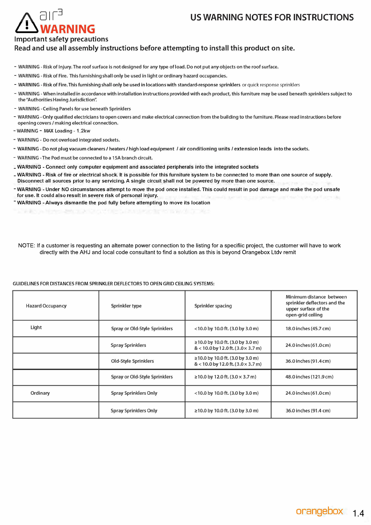
U.S.A. Warning notes……………………………………………………………………………………………………………………1.4
PPE Information……………………………………………………………………………………………………………………………1.5
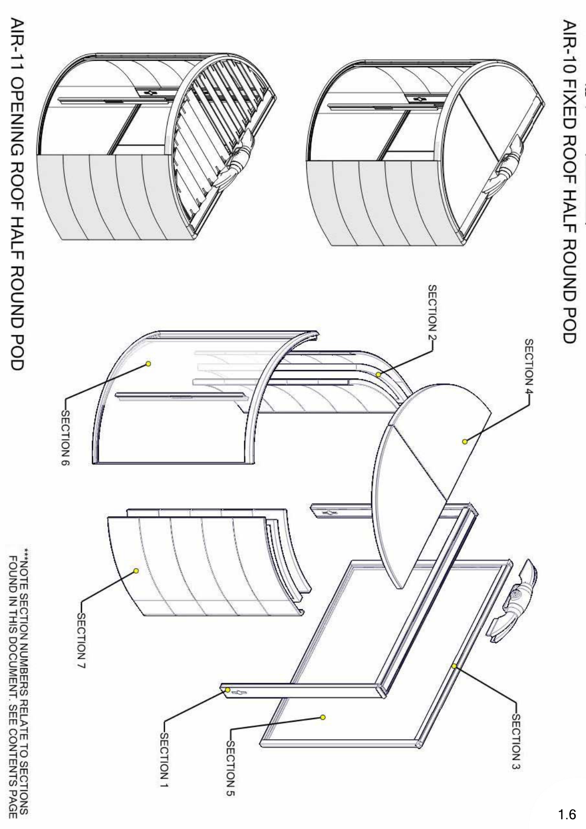
Pod range overview……………………………………………………………………………………………………………1.6 – 1.14
2) Service hoop assembly……………………………………………………………………………………………………………………………………………………………..2.1
Setting out floor jigs…………………………………………………………………………………………………………2.2 – 2.10
Sign off position of pod
Setting out hoop…………………………………………………………………………………………………………………………2.11
Opening hoop covers…………………………………………………………………………………………………………………2.12
UK smoke detector housing………………………………………………………………………………………………………..2.13
Connecting cables in switch side hoop vertical…………………………………………………….........................2.14
Attaching the actuators……………………………………………………………………………………………………2.15 – 2.16
Attaching fan spacer pad……………………………………………………………………………………………………………2.17
Separating fan from the main body…………………………………………………………………………………………….2.18
Securing main fan body to hoop…………………………………………………………………………………………………2.19
Installing fan to main body…………………………………………………………………………………………………………2.20
UK smoke detector housing…………………………………………………………………………………………..2.21 – 2.21.1
US heat detector mounting…………………………………………………………………………………………..2.21.2-2.21.3
Connecting cables in switch side hoop vertical……………………………………………………........2.21.1 / 2.21.3
Connecting cables in power side hoop vertical……………………………………………………………………………2.22
Electrical Schematic layouts……………………………………………………………………………………………..2.23 – 2.28
Connecting hoop vertical to hoop horizontal………………………………………………………………………………2.29
Standing hoop up……………………………………………………………………………………………………………………….2.30
3) Main screens assembly……………………………………………………………………………………….……………………………………………………………………3.1
Hooking screens into hoop and checking hook positions……………………………………………………………….3.2
Order of attaching screens to hoop………………………………………………………………………………………………3.3
Attaching hoop brackets and checking alignments……………………………………………………………………….3.4
Attaching top screen covers to check alignments………………………………………………………………………….3.5
Attaching fan cowls and plugging fan in……………………………………………………………………………………….3.6
4) Front and back glass frame assemblies…………………………………………………………………………………………………………………………………….4.1
Square frame assembly option 1……………………..……………..…………………..……………………………………….4.2
General assembly of the frame…………………………………………………………..………………………………………..4.3
Front frame assembly………………………………………………..……………………………………………………..4.4 – 4.4.1
Back frame assembly……………………………….……………………………………………………………………….4.5 – 4.5.1
Attaching the assembled frames to the pod………………….………………………………………………….4.6 – 4.6.1
Square frame assembly option 2…………………………………..………………………………………………………………4.7
Location of bottom door tracks………………………………..…………………………………………………………………..4.8
Locating uprights onto bottom door track…………………………….………………………………………………………4.9
Attaching uprights onto main screens………………………………..………………………………………………………4.10
Locating top
crossbar…………………………………………………………..…………………………………………………….4.11
Round frame assembly option 1……………………………………………..………………………………………………….4.12
Attaching the assembled frames to the pod………………………..……………………………………………………..4.13
Round frame assembly option 2………………………………………..……………………………………………………….4.14
Location of bottom door tracks………………………………………..…………………………………………………………4.15
Locating uprights onto bottom door track………………………..………………………………………………………..4.16
Attaching uprights onto main screens..………………………….………………………………………………..4.17 – 4.18
Locating top crossbar………………………………………………………………………………………………………………….4.19
Mini Pod ………………………………………………………………………….…………………………………………………………4.20
5) Opening and fixed roof assemblies…………………………………………………………………………………………………………………………………………..5.1
Fixed roofs………………………………………………………………………………………………………………………………………………….…………………………….5.2
Attaching fixed roof supports……………………………………………………………………………………………………….5.3
Positioning the fixed roof panels…………………………………………………………………………………………………..5.4
Profile views of installed roof panels (fixed)………………………………………………………………………………….5.5
Attaching safety clips onto fixed roof panels……….……………………………………………………………………….5.6
Opening roofs………………………………………………………………………………………………….……………………………………………………………………….5.7
Adding actuator cowl covers…………………….………………………………………………………..………………………..5.8
Positioning the opening roof panels……..………………………………………………………………..…………………….5.9

Profile views of installed roof panels (opening)…………..………………………………………………………………5.10
Attaching crank arm to main actuator body………….…………………………………………………………5.11 – 5.12
Checking that roof blades are completely closed…………………………………….…………………………………5.13
Adjustment of actuators to aid in closing roof blades…………………..…….…………..…………………………5.14
Securing crank arms to main body and replacing cowls………….…..…….…………………………….5.15 – 5.17
Sign off position of pod
6) Front and back glass……………………………………………………………………………………………………...............................................................6.1
Position of glass panels within different pod models……………………………………………………..6.1.1 – 6.1.9
Positions of the protective glass strips………………………………………………………………………………….6.2 – 6.4
Rear Glass…………………………………………………………………………………………………………………………………….6.5
Bonding the joining strip to the glass……………………………………………………………………………………………6.6
Loading the glass into the frame…………………………………………………………………………………………………..6.7
Levelling the glass…………………………………………………………………………………………………………………………6.8
Preparing the joining strips…………………………………………………………………………………………………………..6.9
Joining the glass…………………………………………………………………………………………………………………………6.10
Sealing the glass………………………………………………………………………………………………………………6.11 – 6.12
Securing the glass with metal clamping brackets……………………………………………………………………….6.13
Front glass …………………………………………………………………………………………………………………………………6.14
Bonding the joining strip to the glass………………………………………………………………………………………….6.15
Loading the glass into the frame…………………………………………………………………………………………………6.16
Packing the top crossbar against the glass…………………………………………………………………………………6.17
Levelling the glass………………………………………………………………………………………………………………………6.18
Preparing the joining strips…………………………………………………………………………………………………………6.19
Joining the glass…………………………………………………………………………………………………………………………6.20
Sealing the glass………………………………………………………………………………………………………………6.20 – 6.22
7) Glass door Installation...................................................................................................................................................................7.1
Assembling door runners……………………………………………………………………………………………………………..7.2
Bottom door track glides into glass……………………………………………………………………………………………..7.3
Lifting door onto track…………………………………………………………………………………………………………………7.4
Levelling door…………………………… ………………………………………………………………………………………..7.5 – 7.7
Door handle assembly………………………………………………………………………………………………………………….7.8
Back door edge seal……………………………………………………………………………………………………………………..7.9
Top corner finishing caps…………………………………………………………………………………………………………….7.10
Door stop……………………………………………………………………………………………………………………………………7.11
Door track cover clips…………………………………………………………………………………………………………………7.12
Door track / rear covers………………………………………………………………………………………………………………7.13
8) Upholstery panels assembly…………………………………………………………………………………………………………………………………………………….8.1
Fabric panel tolerances…………………………………………………………………………………………………………………8.2
Attaching external upholstery panels……………………………………………………………………………………………8.3
Removing anti slip bung mouldings………………………………………………………………………………………………8.4
Adding bottom corner mouldings…………………………………………………………………………………………………8.5
Positions of clips on external square pod panels……………………………………………………………………………8.6
Fastening external upholstery panels with fixings…………………………………………………………………………8.7
Attaching internal upholstery panels…………………………………………………………………………………………….8.8
Positions of clips on external square pod panels…………………………………………………………………………..8.9
Sign off position of pod
9) Accessories……………………………………………………………………………………………………………………………………………………………………………….9.1
Screen mounted whiteboards………………………………………………………………………………………………9.2 – 9.5
Screen mounted fixed monitor brackets……………………………………………………………………………..9.6 – 9.10
Hoop mounted adjustable arm…………………………………………………………………………………………9.11 – 9.16
Hoop mounted fixed bracket……………………………………………………………………………………………9.17 – 9.22
Hoop mounted tables………………………………………………………………………………………………………9.23 – 9.29
Mini pod tables………………………………………………………………………………………………………………9.30 – 9.36
10) The knack……………………………………………………………………………………………………………………………………………………….10.1 (10.1 - 10.17)
The knack contents page…………………………………………………………………………………………………………10.1.1
11) Fault Finding………….………………….……………………………………………………………………………………………………………………11.1 (11.1 - 11.34)
Fault Finding contents Page………………………………………………….…………………………………………………11.2

orange box
0 I 13
Supporting documents
1.1

TOOLS / EQUIPMENT REQUIRED FOR INSTALL
Quantity Description
2Vacuum Suction Cups - 8" or 9" (With Low Vacuum Audio Alarm)
1 Safety Glassesn(1 pair per installer)
1Safety Gloves (1 Pair per installer)
2Plastic Gasket Roller (Tool to seal glass) -Provided by Orangebox
1Jig
Pack Isopropanol (IPA) Wipes
Glass Items
Tools/Equipment
Quantity Description
1Cordless Drill
1Phillips #3 Driving Bit (for drill)
26ft Folding Ladder
1White Mallet
1Touch Up Paint -Provided By Orangebox
2Glazing Shovel (Plastic Hoop Opener) -Provided by Orangebox
1Straight Cut Aviation Snips (or similar)
1Metric T-Handle Hex Key - 2.5mm
1Metric T-Handle Hex Key - 3.0mm
1Metric T-Handle Hex Key - 4.0mm
1Metric T-Handle Hex Key - 5.0mm
1Metric T-Handle Hex Key - 6.0mm
113mm 12-Point Metric Combination Wrench
1Torque Wrench (Must Reach 14NM/10.32 ft lbf/124 in lbf)
15mm Hex Bit Socket (For Torque Wrench)
16mm Hex Bit Socket (For Torque Wrench)
1Retractable Utility Knife
112" Medium Trigger Clamp
116' Tape Measure
18" Linesman Pliers (or similar)(used for knockdown of Pod)
1.2

112" Wonder Nar Pry Bar (or similar)
1NM Gauge
1Hoop Leaver
1 T-Handle Flat
1Screw Driver
1Small Driver
1Small Crossbar
1Roller
1Spirit Level
1Trigger Clamps
112mm VHB TPE / Electrical Tape
Pack Isoproponal (IPA) Wipes
1No 13 Spanner
1Amored Corner Protectors
8Floor Slide Guides
110mm Spanner
1Steamer
1Circuit Tester Pen + Plug Socket Tester
Tools/Equipment
Alignment Jigs
Jigs Pods Page
Half Round Pod Alignment Jig Air -10 2.3
Air -11
Round Pod Alignment Jig Air -12 2.4
Air -13
Logenze Pod Alignment Jig Air -14 2.5
Air -15
3x3 Soft Corner Alignment Jig Air -16 2.6
Air -17
Mini Pod Alignment Jig Air -20 2.7
Half Square Pod Alignment Jig Air -22 2.8
Air -23
Square Pod Alignment Jig Air -24 2.9
Air -25
Rectangle Pod Alignment Jig Air -26 2.10
Air -27
3 x 3 Square Pod Alignment Jig Air -28 2.11
Air -29
1.3

NOTE: If a customer is requesting an alternate power connection to the listing for a specifiic project, the customer will have to work
directly with the AHJ and local code consultant to find a solution as this is beyond Orangebox Ltdv remit

1.5

1.6


1.8

1.9

1.10

1.11

1.12

1.13

1.14


ONE PERSON MINIMUM

BUILD THE CURVED
CONNECTOR PARTS
(NUMBERED 4) AROUND
THE CENTRAL HOOP
ALIGNMENT JIG
1
2x
2
2x
3
1 OF EACH x
4
4x
OPEN AND CORRECTLY POSITION
THE HOOP ALIGNMENT JIG
PARTS FIRST (NUMBERED 1)
COMPLETE THE OVERALL JIG
BY CONNECTING THE FRONT
ALIGNMENT PARTS (NUMBERED 5 &6)
FINALLY, USE THE AIR-JIG-008
HOOP SET SQUARE PARTS TO
CHECK THE VERTICAL ANGLE OF THE
HOOP UPRIGHTS
KIT CONTENTS:
2 X AIR-JIG-001
2 X AIR-JIG-004
1X AIR-JIG-005-01
1 X AIR-JIG-005-02
HALF ROUND ALIGNMENT JIG
REV0
2.3
This manual suits for next models
4
Table of contents