DROPPER OC26 | ORBEA TECHNICAL MANUAL OC | 7
EN
INSTALLING THE SEATPOST
MATERIALS AND TOOLS NEEDED
Allen keys:
· 2.5mm
· 3mm
· 4mm
· 5mm
OC2 DROPPER INSTALLATION
· Torque wrench
· Cable cutters
· Lithium grease/carbon assembly compound
· Gear cable
· Gear outer cable and 4mm ferrules
· Metal cable end
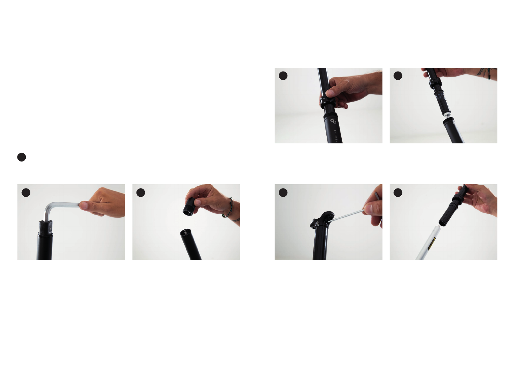
Install the outer cable into the frame following the frame´s
specic routing. Intruduce it into the port on the front of
the bike and guide it until it comes out of the seat tube.
20-25cm should protrude out of the seat post.
If your bike already had a seatpost installed, disassemble
it from the bike before installing the outer cable into the
frame.
On new bikes equipped with the OC2 dropper, the outer
cable might already be installed.
Install a 4mm plastic ferrule on the outer cable end co-
ming out of the seatpost. Insert this end of the outer cable
into the seatpost actuator´s housing.
Insert the seatpost into the seat tube until it reaches the
minimum insertion mark and tighten the seatpost clamp
(5Nm-6Nm).
If you know the nal saddle height, you can insert the
seatpost (fully extended) until the desired saddle height
is reached so a shorter lenght of outer cable is needed.
Tighten the seatpost clamp (5Nm-6Nm).
Take the outer cable end at the front of the bike to the
remote lever to determine the lenght needed. Turn the
handlebar both ways to ensure they turn free all the way
and the outer cable does not interfere with other cables
or components.
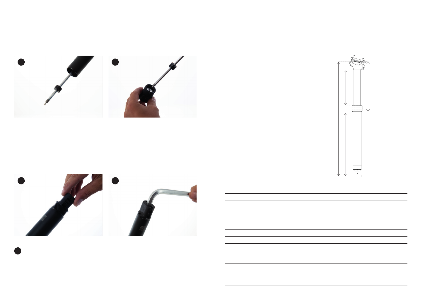
Cut the outer cable using a bike specic cable cutter. Insta-
ll a 4mm plastic ferrule onto the outer cable´s end.
Loosen the seatpost clamp and pull from the OC Dropper
seatpost until it is out of the seat tube. Push the outer
cable from the end of the bike until a portion protrudes
from the seat post.
Install the OC Components or Shimano SL-MT800-L I-Spec
remote lever on your preferred position on the left side of
the handlebar.
Insert a gear cable into the outer cable from the seatpost
end.
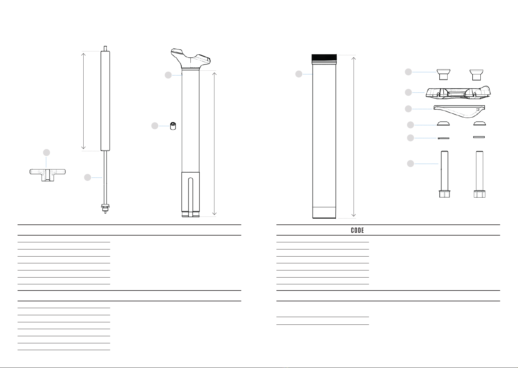
1 2
3
6
4
5 7