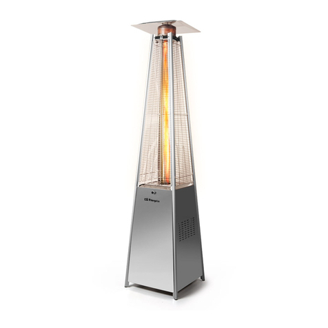
Orbegozo PHE 50 User manual

ESTUFA DE GAS – M ANUAL DE INSTRUCCIONES
GAS PATIO HEATER - INSTRUCTION M ANUAL
POÊLE À GAZ - M ANUEL D’INSTRUCTIONS
FOGÃO A GÁS- M ANUAL DE INSTRUÇÕES
PHE 50 PHE 70
Sonifer, S.A.
Avenida de Santiago, 86
30007 M urcia
España
E-mail: sonifer@sonifer.es
Lea atentamente este manual ant es de ut ilizar este aparat o y guárdelo para futuras consultas.
Sólo así podrá obt ener los mejores resultados y la máxima seguridad de uso.
Read this manual carefully before running t his appliance and save it for reference in order t o
obt ain the best results and ensure safe use.
Veuillez lire at tentivement ce manuel avant d’utiliser cet appareil et conservez-le pour tout e
consultation future. C’est la seule façon d’obt enir les meilleurs résult at s et une sécurit é
opt imale d’ut ilisat ion.
Leia este manual cuidadosamente antes de ut ilizar est e aparelho e guarde-o para consulta
futura. Só assim, poderá obter os melhores resultados e a máxima segurança na utilização

PHE 50 PHE 70
2
ESPAÑOL
CONSEJOS IM PORTANTES
•Lea atentamente las instrucciones de este manual. Contiene información importante
para el uso como para su seguridad.
•No ponga en marcha un aparato dañado.
•El mantenimiento y reparación de este aparato, debe realizarlo un técnico autorizado.
Si no se respetan estas instrucciones, corre el riesgo de perder la garantía.
•Este aparato puede ser instalado y puesto en marcha por el propio usuario, siguiendo
tanto las instrucciones de instalación como la Normativa Oficial referente a
instalaciones de gas. No obstante si quiere sentirse tranquilo, recomendamos que esta
operación la encomiende a las manos expertas de un Técnico autorizado.
•Conserve este libro de instrucciones, puede servirle para recordar consejos e
instrucciones, y eventualmente ser de utilidad a otro usuario. Si se le extravía, no dude
solicitar un nuevo ejemplar en nuestra Red de Servicio Técnico.
•Para utilizar en el exterior y en zonas bienventiladas. Una zona bienventilada debe
tener al menos el 25% de su superficie abierta. La superficie se calcula con la suma de
la superficie de las paredes.
•No obstruya los orificios de ventilación de la carcasa del cilindro.
•No mueva la estufa mientras está funcionando.
•Cierre la válvula de la botella de gas o del regulador antes de mover la estufa.
•Se debe aplicar la normativa local al instalar la estufa y a la hora de guardar la botella
de gas.
•El tubo o la manguera flexible deben cambiarse cumpliendo los intervalos
establecidos.
•Utilice sólo el tipo de gas y botella especificados por el fabricante.
•En caso de viento fuerte se debe llevar cuidado para evitar que se vuelque la estufa.
INSTRUCCIONES DE SEGURIDAD
•La instalación y las reparaciones las debe realizar un técnico cualificado.
•Una instalación incorrecta, los ajustes o las modificaciones pueden provocar lesiones
personales o daños materiales.
•No intente modificar el aparato de ninguna manera.
•No cambie ni sustituya el regulador por un regulador distinto del repuesto original
sugerido por el fabricante.
•No almacene o utilice gasolina u otros vapores o líquidos inflamables en la estufa.
•Todo el sistema de gas, el regulador de la manguera, el piloto o el quemador deben
inspeccionarse para ver si tiene fugas o daños antes de utilizar la estufa.
•Todas las pruebas de fugas se deben realizar con solución jabonosa. No utilice nunca
unallama abierta para comprobar si hay fugas.
•No utilice la estufa hasta que haya comprobado que no hay fugas en las conexiones.
•Apague inmediatamente la válvula de gas si detecta el mínimo olor a gas.
•No traslade la estufa mientras está funcionando.

PHE 50 PHE 70
3
•No mueva la estufa después de haberla apagado hasta que se haya enfriado.
•M ant enga limpia la abertura de ventilación de la carcasa para la botella.
•No pinte la pantalla radiante, el panel de control o la cubierta protectora del reflector.
•Se deben mantener limpios el compartimento para los controles, el quemador y los
conductos de aire de circulación de la estufa.
•Se deben limpiar tantas veces como sea necesario.
•El depósito de gas LP se debe apagar cuando no se está utilizando la estufa.
•Revise inmediatamente la estufa si ocurre cualquiera de estas cosas:
- La estufa no se calienta y no alcanza la temperatura adecuada.
- El quemador hace un gorgot eo durante el uso (un ligero ruido es normal
cuandoel quemador está apagado).
- Hay olor a gas y las llamas del quemador tienen un color amarillo intenso.
•El montaje de la manguera/ regulador de LP no debe estar en lugares donde la gente se
pueda tropezar y nunca en una zona donde la manguerapueda sufrir daños
accidentales. Cualquier protección o dispositivo protector retirado para el
mantenimiento de la estufa debe sustituirse antes de poner en funcionamiento la
estufa.
•Cambie la botella de gas en una zona bienventilada, lejos de cualquier fuente
inflamable.
•Compruebe queel sello del regulador está colocado y que está en buen estado.
•No obstruya los orificios de ventilación del alojamiento de la botella.
•Tanto los adultos como los niños deben mantenerse alejados de las superficies a alta
temperatura para evitar quemaduras o que se prenda fuego a la ropa.
•Los niños deben estar vigilados siempre que estén en la zona donde se encuentra la
estufa.
•No se debe colgar ropa u otros materiales inflamables en la estufa ni tampoco
colocarla sobre la estufa o cerca de ésta.
•Características del LP: inflamable, explosivo, más pesado queel aire por lo que se
queda en las zonas bajas.
•En su estado natural, el propano no huele mal. Por su seguridad, se añade una
sustancia quehuele a col podrida.
•El contacto con LP puede ocasionar quemaduras por frío en la piel.
•Esta estufa se entrega de fábrica sólo para uso de gas LP.
•Utilice únicamente botellas de gas LP de “ 20lb” con la certificación de la CEE (las
mismas que se utilizan normalmente en las cocinas de gas) con válvulas de seguridad.
•Estas válvulas se pueden identificar rápidamente por sus roscas externas e internas.
•No utilice nunca una botella con el cuerpo, la válvula, el cuello o el aro de base
dañados.
•Si la estufa no se está utilizando, la válvula de control debe estar apagada.
•Realice siempre una prueba de fugas en las conexiones de gas cuando conecte una
nueva botella (consulte la pág. 4). No utilice nunca una llama para realizar la prueba de
fugas ni fume durante la misma.
•Importante: La pantalla antillamas es una pieza que se desgasta rápidamente.

PHE 50 PHE 70
4
•ATENCIÓN: Para evitar sobrecalentamiento, no cubra la estufa.
•¡Precaución! La superficie permanece caliente durante y despues de su uso
•El aparato no está destinado para el uso por parte de niños o personas con problemas
físicos o mentales y sin experiencia ni conocimientos, a menos que lo hagan bajo
control de un responsable o profesional para el uso del aparato.
•PRECAUCIÓN: Para la seguridad de sus niños no deje material de embalaje (Bolsas de
plástico, cartón, polietileno etc.) a su alcance.
RECOM ENDACIONES PARA LA INSTALACIÓN
Es importante seguir las especificaciones que la Normativa legal vigente establece para el
emplazamiento y puesta en marcha de este aparato, por lo que le recomendamos consulte a
un técnico autorizado. No obstante si decide prescindir de dicha consulta, seguidamente le
relacionamos las más importantes.
SOPORTE DEL CALEFACTOR Y COLOCACIÓN
-La estufa es principalmente para uso en el exterior. Asegúrese siempre de que hay buena
ventilación.
- M antenga la distancia adecuada a los materiales combustibles, al menos 45 cm (18” ) EN la
parte superior y 60 cm (24” ) en los laterales.
- La estufa debe colocarse sobre una superficie dura y nivelada.
- Nunca utilice la estufa en una atmósfera con peligro de explosión como zonas donde se
guarda gasolina u otros líquidos o vapores inflamables.
-Para proteger la estufa del viento fuert e, ancle la base al suelo con tornillos.

PHE 50 PHE 70
5
REQUISITOS PARA EL GAS
- Utilice sólo botellas de butano o propano.
- La presión de entrada máxima del regulador de propano no debe superar 100 PSI.
- Se necesita una presión de suministro mínima de 28 mbar (11.0” W.C.) para realizar el ajuste
de la entrada de gas propano.
- El regulador de presión y el montaje de la manguera se debe utilizar para cumplir la
normativa local.
- La instalación debe cumplir lo que establezca la normativa local y, si no existiera, la normativa
estándar.
- La instalación debe cumplir la normativa local y si no existiera, debe cumplir la normativa
para almacenaje y manipulación de gases de petróleolíquido.
- Un depósito de propano con hendiduras, oxidado o dañado puede ser peligroso y debe ser
revisado por el proveedor del mismo.
No utilice nunca un depósito de propano con una conexión de válvula dañada.
- El depósito de propano se debe colocar de manera que pueda salir vapor desde la botellaque
está funcionando.
- No conecte nunca un depósito de propano no regulado a la estufa.
PRUEBA DE FUGAS
Las conexiones de gas de la estufa vienen probadas de fábrica. En el lugar donde se vaya a
colocar se debe realizar una comprobación del ajuste ya que podría haber existido algún
cambio por la manipulación en el envío o por si se hubiera aplicado presión excesivasobre la
estufa.
-La estufa se debe revisar con una botellallena.
-Compruebe que la válvula de control de seguridad está en la posición OFF (APAGADA).
-Prepare una solución jabonosa con una parte de detergente y una parte de agua. La solución
jabonosa se puede aplicar con un espray, cepillo o paño.
-En caso de fuga aparecerán pompas.
-Enciendael suministro de gas.
-En caso de fuga, apague el suministro de gas. Apriete cualquier accesorio que tenga fugas,
vuelva a encender el suministro de gas y compruébelo de nuevo. Póngase en contacto con su
distribuidor si sigue habiendo burbujas.
-Nunca realice una prueba de fugas fumando al mismo tiempo.
OLOR A GAS
Al gas LP y al gas natural se le añaden sustancias olorosas artificiales para detectar las fugas de
gas.
Si ocurre una fuga de gas, usted podrá oler a gas. Puesto queel propano (LP) pesa más que el
aire olerá a gas cerca del suelo. ¡CUALQUIER OLOR A GAS ES LA SEÑAL PARA TOM AR LAS
M EDIDAS ADECUADAS!
-No haga nada quepueda hacer prender el gas. No haga funcionar ningún interruptor
eléctrico. No tire de ningún cable eléctrico o alargadera. No encienda cerillas o cualquier
fuente de llamas. No utilice el teléfono.
-Saque a todo el mundo del edificio y aléjese de la zona inmediatamente.

PHE 50 PHE 70
6
-Cierre todas las válvulas de suministro de combustible de botella o depósito de gas propano
(LP) o la válvula principal de combustible del medidor si utiliza gas natural.
-El gas propano (LP) pesa más que el aire y se queda en las zonas bajas. Si tiene algún motivo
para sospechar de una fuga de propano, manténgase alejado de las zonas bajas.
-Utilice el teléfono de algún vecino para llamar al distribuidor de gas y a los bomberos. No
vuelva a entrar al edificio o a la zona.
-Quédese fuera del edificio y manténgase alejado de la zona hasta que los bomberos y el
distribuidor de gas garanticen que es seguro.
-FINALM ENTE, permita queel técnico del servicio de gas y los bomberos revisen si hay un
escape de gas. Pídales que aireen el edificio y la zona antes de volver. Técnicos de servicio
cualificados deben reparar cualquier fuga, revisar otras fugas y volver a encender el aparato
por usted.
FUNCIONAM IENTO Y ALM ACÉN
PARA ENCENDER LA ESTUFA
1. Lleve la válvula de la botella de gas a la posición de encendida.
2. Pulse y gire el selector de control variable a la posición PILOTO (90º en sentido contrario a
las agujas del reloj)
3. Pulse el selector de control variable y manténgalo pulsado durante 30 segundos. M antenga
pulsado el selector de control variable después de que se encienda la llama del piloto.
Importante:
Si se acaba de conectar un nuevo depósito, deje al menos un minuto para que salga el aire en
la tubería de gas y así purgarlo a través del orificio del piloto.
Al encender la llama del piloto asegúrese de queel selector de control variable está pulsado
mientras pulsa el botón de encendido. El selector de control variable se puede soltar unavez
encendida la llama del piloto.
La llama del piloto se puede ver y revisar a través de la pequeña ventana redonda con tapa
deslizante ubicada en la parte inferior de la pantallaantillamas (a la izquierda o a la derecha
del controlador).
Si la llama del piloto no se enciende o se apaga, VUELVA A REPETIR EL PASO 3.
4. Después de que se haya encendido la llama del piloto, gire el selector de control variable a la
posición mínima y manténgalo así durante 5 minutos o más antes de girar el selector a la
posición de temperatura deseada.
PARA APAGAR LA ESTUFA
1. Gire el selector de control variable a la posición piloto.
2. Pulse y gire el selector de control variable a la posición OFF.
3. Apague completamente la válvula de la botella de gas.

PHE 50 PHE 70
7
LIM PIEZA Y M ANTENIM IENTO
Limpie las superficies recubiertas de polvo con un paño suave yhumedecido. Para superficies
lacadas, utilice los limpiadores adecuados. No limpie la estufa con limpiadores combustibles o
corrosivos.
Retire la suciedad del quemador para mantenerlo limpio y seguro para el uso.
ALM ACÉN
1. Cierre siempre la válvula de gas de la botella de gas después de utilizarla o en caso de que
ocurra algo anormal.
2. Retire el controlador de presión y la manguera.
3. Compruebe el ajuste de la válvula de gas y revise también si hay daños. Si sospecha de algún
daño, pida a su distribuidor de gas que la cambie.
4. Nunca guarde una botella de gas líquido en un sótano o en lugares en los que no haya la
ventilación adecuada.
PIEZAS Y CARACTERÍSTICAS
A. M ontaje y características:
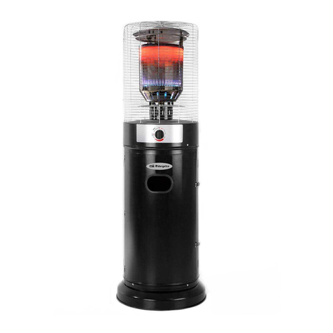
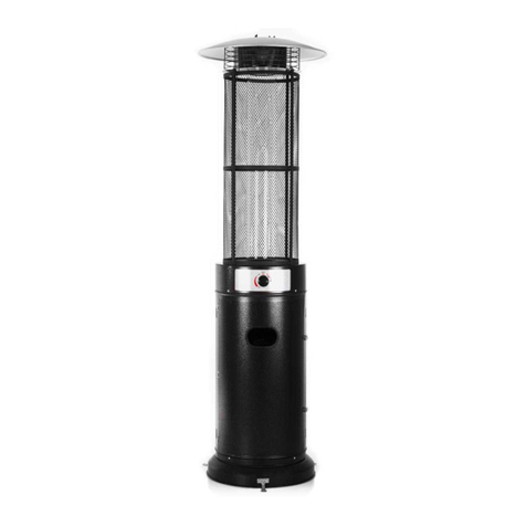
Estufa móvil para terraza / jardín con alojamiento
para depósito
Carcasa en acero recubierto en polvo o acero
inoxidable
Conexiones de gas soluble equipadas con
abrazadera de metal
Pantallade acero inoxidable para la llama
Emisión de calor desde el reflector
B. Características
Solamente para uso exterior.
Utilice sólo botellas de butano o propano
Vataje máx.: 12000 vatios
Vataje mín.: 5000 vatios
Consumo: 450 g/ h – 870 g/ h
Peso: M odelo de acero inoxidable G.W 20 kg
M odelo recubierto con polvo G.W. 22 kg
Altura: 2210 mm incluida la base
Con certificado CE

PHE 50 PHE 70
8
C. Tabla de aperturas
Presión del Gas mmH
2
O Abertura principal Abertura del quemador del piloto
280/ 330 1.90 mm 0.18 mm
5001.80 mm 0.18 mm
PIEZAS Y PROCEDIM IENTOS DE M ONTAJE
Herramientas necesarias:
Abra el extremo con la llave de 10 & 13 mm
Llave de apertura ajustable (2) 8” de longitud
Alicates de 9”
Destornillador Phillips con hoja media
Cinta de teflón para las juntas
Bote pulverizador con solución jabonosa para la prueba de fugas
Piezas suministradas:
Base con carcasa para el depósito de LPG
Poste de montaje con 3 soportes
Tubo de acero galvanizado de 10 mm x 86 cm (L)
Reflector de 810 mm con 6 arandelas de Ø8 mm y 3 tuercas almenadas
3 pasadores de 60 mm (L) para el soporte del reflector.
4 pernos M 6 x 10 mm para el poste y poste y quemador
6 pernos y tuercas M 6 x 35 mm para el poste y los soportes del poste
3 pernos M 8 x 16 mm para los soportes del poste y la base
3 fijadores a tierra
6 pernos y tuercas M 6 x 10 mm para los fijadores a tierra
Procedimientos de montaje
PASO 1
1-1. Coloque los tres soportes del poste en su posición en la base tal y como muestra la
imagen.
1-2. Utilice 3 pernos M 8 x 16 mm para unir los soportes del poste y la base.

PHE 50 PHE 70
9
PASO 2
2-1. Coloque el poste en la parte superior de los 3 soportes del poste.
2-2. Utilice 6 pernos y tuercas M 6 x 35 mm para conectar el poste a los 3 soportes. Apriete los
pernos y las tuercas.
PASO 3
3.1. Introduzca la carcasa para el depósito en el poste.

PHE 50 PHE 70
10
PASO 4
4-1. Introduzca la tuerca del tubo de gas de acero en el conector
de la salida de gas del quemador.
4-1-1. Asegure los pernos del soporte del reflector en la
cubierta de la pantalla antillamas con 3 pasadores de 60 mm de
longitud y 3 arandelas de Ø8 mm.
4-1-2. Conecte los pasadores y las arandelas a la pantalla
antillamas.
4-1-3. Apriete los pasadores.
4-2. Apriete la tuerca del tubo de gas de acero y la rosca de
entrada de gas.
4-3. Coloque el quemador con el tubo de acero en el poste.
4-4. Fije la base del quemador al post e con 4 pernos M 6 x 10
mm.
PASO 5
5-1. Compruebe si la conexión del poste vertical y el quemador
están montados según las instrucciones y si todos los pernos y
tuercas están bien apretados.
5-2. Coloque la arandelaplana en la parte superior de cada
perno del soporte del quemador/ reflector
(Rosca M 8).
PASO 6
6-1. Coloque el reflector en la parte superior del quemador
pasando a través de los 3 pernos de soporte del
quemador/ reflector.
6-2. Coloque las arandelas en cada perno de soporte y apriete
cada una con una tuerca almenada M 8.
PASO 7
7-1. Levante la carcasa del depósito y déjela descansar sobre la
placa del poste.
7-2. M onte la manguera de caucho del regulador de gas con el
extremo roscado del tubo de acero de entrada de gas y apriete
la tuerca.
7-3. Conecte el regulador con el depósito de gas LPG en sentido
contrario a las agujas del reloj y apriételo con unallave
ajustable.
7-4. Coloque el depósito de gas LPG en la base.

PHE 50 PHE 70
11
LISTA DE COM PROBACIÓN DE PROBLEM AS
PROBLEMA CAUSA PROBABLE SOLUCIÓN
El piloto no se enciende Válvula de gas apagada Encienda la válvula de gas
Depósito de gas vacío Llene el depósito de LPG
Abertura bloqueada Limpie o sustituya la abertura
Aire en el sistema de
suministro
Purgue el aire
Conexión suelta Compruebe todos los accesorios
El piloto no se mantiene
encendido
Suciedad alrededor del piloto Limpie la zona sucia
Conexiones sueltas Apriete las conexiones
Termopar en mal estado Sustituya el termopar
Fuga de gas en el tubo Revise las conexiones
Falta de presión del
combustible
Depósito casi vacío. Llene el
depósito de LPG.
El quemador no se
enciende
Presión baja Depósito casi vacío. Llene el
depósito de LPG.
Abertura bloqueada Retírela y límpiela
El control no está en la
posición de encendido
Lleve la válvula a la posición
ENCENDIDO
Termopar en mal estado Sustituya el termopar
Montaje de la luz del piloto
lado
Coloque el piloto adecuadamente
No está en la ubicación
correcta
Colóquelo en la posición correcta y
vuelva a intentarlo

PHE 50 PHE 70
12
ENGLISH
IM PORTANT ADVICE
•Read the instructions in this manual carefully. It has important information both for
operational use and for your safety.
•Do not start up faulty apparatus.
•M aintenance and repairs should be carried out by a qualified technician. If these
instructions are not abided by, there is a risk of annulling the guarantee.
•This apparatus can be installed and started up by the user following both the fitting
instructions as well as the Official Regulations on gas installations. However, if you
want to be quite sure, we would recommend that this task be placed in the expert
hands of an authorized technician.
•Keep this instruction manual as it can be useful for reminding you of advice and
instructions and for any other user. If it is lost, do not hesitate to ask for another copy
from our Technical Service Network.
•For use outdoors and in well ventilated areas. A well ventilated area must have a
minimum of 25% of the surface area open.The surface area is the sum of the walls
surface.
•Do not obstruct the ventilation holes of the cylinder housing.
•Do not move the appliance when in operation.
•Shut off the valve at the gas cylinder or the regulator before moving the appliance.
•This appliance must be installed and the gas cylinder stored in accordance with the
regulation in force.
•The tubing or the flexibile hose must be changed within the prescribed intervals.
•Use only the type of gas and the type of cylinder specified by the manufacturer.
•In case of violent wind particular attention must be taken against tilting of the
appliance.
SAFETY RECOM M ENDATIONS
•Installation and repair should be done by a qualified service person.
•Improper installation, adjustment, alteration can cause personal injury or property
damage.
•Do not attempt to alter the unit in any manner.
•Never replace or substitute the regulator with any regulator other than the factory-
suggested replacement.
•Do not store or use gasoline or other flammable vapors or liquids into the heater unit.
•The whole gas system, hose regulator, pilot or burner should be inspected for leaks or
damages before use.
•All leak tests should be done with a soap solution. Never use an open flame to check
for leaks.
•Do not use the heater until all connections have beenleak tested.
•Turn off immediately the gas valve if smell of gas is detected.
•Do not transport heater while it’s operating.
•Do not move the heater after it has been turned off until the temperature has cooled
down.
•Keep the ventilation opening of the cylinder enclosure free and clear of debris.
•Do not paint radiant screen, control panel or top canopy reflector.

PHE 50 PHE 70
13
•Control compartment, burner and circulation air passageways of the heater must be
kept clean.
•Frequent cleaning may be required as necessary.
•The LP tank should be turned off when the heater is not in use.
•Check the heater immediately if any of the following exists:
- The heater does not reach temperature.
- The burner makes popping noise during use (a slight noise is normal when the
burner is extinguished).
- Smell of gas in conjunction with extreme yellow tipping of the burner flames.
•The LP regulator/ hose assembly must be located out of pathways where people may
trip over it or in area where the hose will not subject to accidental damage.
•Any guard or other protective device removed for servicing the heater must be
replaced before operating the heater.
•Change the gas cylinder in a well ventilated area ,away from any inflammation source.
•Check that the regulator seal is fitted and that it is in good condition.
•Do not obstruct the ventilation holes of cylinder housing.
•Adults and children should stay form high temperature surface to avoid burns or
clothing ignition.
•Children should be carefully supervised when they are in the area of the heater.
•Clothing or other flammable materials should not be hung on the heater or placed on
or near the heater.
•LP Characteristics - Flammable, explosive, heavier than air-settles in low areas.
•In its natural state, propane has no odor. For your safety, an odorant is added that
smells like rotten cabbage.
•Contact with liquid LP can cause freeze burns to skin.
•This heater is shipped from the factory for LP gas use only.
•Use only EEC approved ” 20lb.” LP gas cylinders (same as commonly used on gas grills)
with safety valves.
•These valves can be quickly identified by their external and internal threads.
•Never use a cylinder with a damaged body, valve, collar or foot ring.
•When heater is not in use, turn Control Valve OFF.
•Always perform a leak test on gas connections whenever a cylinder is connected (see
Page 4). Never use a flame to test for leaks. Do not smoke while performing a leak test.
•Note: Flame screen is quick-ware part.
•WARNING: In order to avoid overheating, do not cover the heater.
•Caution! The surface remains hot during and after its use
•The appliance isn’t destined for the use of children or person with physical or mental
problems and without experience nor knowledge; unless they make it down control of
a responsible or professional for the use of the appliance.
•WARNING: In order to ensure your children‘s safety, please keep all packaging (plastic
bags, boxes, polystyrene etc.) out of their reach.
INSTALATION RECOM ENDATIONS
It is important the current legal Regulations which lay down the specifications for the fitting
and startup of this apparatus, and so we recommend you consult an authorised

PHE 50 PHE 70
14
technician. However, if you decide not to take this advice, the following is a list of the more
important conditions required for the premises:
HEATER STAND AND LOCATION
-The heater is primarily for outdoor use only. Always ensure that adequate fresh air ventilation
is provided.
-Always maintain proper clearance to combustible materials, i.e. top 45cm(18” ) and sides
60cm (24” ) minimum.
-Heater must be placed on level firm ground.
-Never operate heater in an explosive atmosphere like areas where gasoline or other
flammable liquids or vapors are stored.
-To protect heater from strong wind, anchor the base securely to the ground with screws.
GAS REQUIREM ENTS
-Use propane or butane gas only.
- M aximum inlet pressure of propane regulator must not exceed100 PSI.
- A minimum supply pressure of 28 mbar (11.0” W.C.) is required for the purpose of input
adjustment for propane gas.
- The pressure regulator and hose assembly to be used must conform to local standard codes.
- The installation must conform to local codes, or in the absence of codes, with standard codes.
- The installation must conform to local codes, or in the absence of codes, with the standard
for storage and handling of liquid petroleum gases.
- A dented, rusted or damaged propane tank may be hazardous and should be checked by your
tank supplier.
- Never use a propane tank with a damaged valve connection.
- The propane tank must be arranged to provide for vapor withdrawal from the operating
cylinder.
- Never connect an unregulated propane tank to the heater.
LEAKAGE TEST
Gas connections on the heater are leak tested at the factory prior to shipment. A complete gas
tightness check must be performed at the installation site due to possible mishandling in
shipment or excessive pressure being applied to the heater.

PHE 50 PHE 70
15
-The heater must be checked with a full cylinder.
-M ake sure the safety control valve is in the OFF position.
-M ake a soap solution of one part liquid detergent and one part water.The soap solution can
be applied with a spray bottle, brush or rag.
-Soap bubbles will appear in case of a leak.
-Turn the gas supply ON.
-In case of a leak, turn off the gas supply.Tighten any leaking fittings, then turn the gas supply
on and recheck.Contact your dealer for assistance if bubbles continue to appear.
-Never leak test while smoking.
FUEL GAS ODOR
LP gas and natural gas have manmade odorants added specifically for detection of fuel gas
leaks.
If a gas leak occurs you should be able to smell the fuel gas. Since Propane (LP)is heavier than
air you should smell for t he gas odor low to the floor. ANY GAS ODOR IS YOUR SIGNAL TO GO
INTO IM M EDIATE ACTION!
-Do not take any action that could ignite the fuel gas. Do not operate any electrical
switches.Do not pull any power supply or extension cords. Do not light matches or any other
source of flame. Do not use your telephone.
-Get everyone out of the building and away from the area immediately.
-Close all propane (LP) gas tank or cylinder fuel supply valves,or the main fuel supply valve
located at the meter if you use natural gas.
-Propane (LP) gas is heavier than air and may settle in low areas. When you have reason to
suspect a propane leak, keep out of all low areas.
-Use your neighbor’s phone and call your fuel gas supplier and your fire department. Do not
reenter the buiding or area.
-Stay out of the building and away from the area until declared safe by the firefighters and
your fuel gas supplier.
-FINALLY, let the fuel gas service person and the firefighters check for escaped gas. Have them
air out the building and area before you return. Properly trained service people must repair
any leaks, check for further leakages, and then relight the appliance for you.
OPERATION AND STORAGE
TO TURN ON THE HEATER
1. Turn on the valve on the gas supply cylinder completely.
2. Press and turn the variable control knob to PILOT position (counter-clockwise 90º)
3. Press down the variable control knob and hold for 30 seconds. While holding down the
variable control knob after the pilot flame lights.
Note:
If a new tank has just been connected, please allows at least one minute for the air in the gas
pipeline to purge out through the pilot hole.
When lighting the pilot flame make sure that the variable control knob is continuously pressed
down while pressing the igniter button. Variable control knob can be released after the pilot
flame lights.
Pilot flame can be watched and checked from the small round window with sliding lid located
at the bottom of the flame screen (to the left or right side of the controller).
If the pilot flame does not light or it goes out,REPEAT STEP 3.
4. After the pilot flame lights, turn the variable control knob to minimum position and leave it
there for 5 minutes or more before turning the knob to desired temperature position.

PHE 50 PHE 70
16
TO TURN OFF THE HEATER
1. Turn the variable control knob to pilot position.
2. Press and turn the variable control knob to OFF position.
3. Turn off the valve on the gas supply cylinder completely.
CLEANING AND CARE
Wipe off powder coated surfaces with soft, moist rag. For lacquer surface, use suitable
cleaners. Do not clean heater with cleaners that are combustible or corrosive.
Remove debris from the burner to keep it clean and safe for use.
STORAGE
1. Always close the gas valve of the gas cylinder after use or in case of a disturbance.
2. Remove the pressure controller and the hose.
3. Check the tightness of the gas valve and for damage. If you suspect a damage, have it
changed by your gas dealer.
4. Never store liquid gas cylinder in a sub-terrain, or at places without adequate air ventilation.
PARTS AND SPECIFICATIONS
A. Construction and characteristics:
Transportable terrace/ garden heater with tank housing
Casing in steel with powder-coating or stainless steel
Soluble gas connections are equipped with metal clamp
Stainless steel flame screen
Heat emission from reflector
B.Specifications
For outdoor use only
Uses propane or butane gas only
M ax. wattage: 12000 watts
M in. wattage: 5000 watts
Consumption: 450 g/ hr – 870 g/ hr
Weight: Stainless steel model G.W. 20 kgs
Powder coating model G.W. 22 kgs
Height: 2210 mm including stand
With CE certificate

PHE 50 PHE 70
17
C. Table of openings
ASSEM BLY PARTS & PROCEDURES
Tools needed:
Open end wrench 10 & 13 mm
Adjustable opening wrench (2) 8’’ long
Slip joint pliers 9” long
Philips screwdriver w/ medium blade
Teflon plumbing tape for joints
Spray bottle of soap solution for leakage test
Parts supplied:
Stand with LPG tank housing
Assembly post with 3 pcs post brackets
10 mm x 86 cm (L) galvanized steel pipe
Reflector 810 mm with 6 pcs washers Ø8 mm and 3 pcs castlesnuts
3 pcs 60mm(L) pins for reflector support.
4 pcs bolts M 6 x 10 mm for post and post and burner
6 pcs bolts & nuts M 6 x 35 mm for post and post brackets
3 pcs bolts M 8 x 16 mm for post brackets and stand
3 pcs ground fixer
6 pcs M 6 x 10 mm ground fixer bolts & nuts
Assembly Procedures
STEP 1
1-1. Put the three pcs post brackets on each position on the base
as shown in the picture.
1-2. Use 3 pcs M 8 x 16 mm bolts to join the post brackets and
stand.
STEP 2
2-1. Put the post onto the top of 3 pcs post brackets.
2-2. Use 6 pcs M 6 x 35 mm bolts and nuts to connect the post to the
3pcs post brackets. Tighten the bolts and nuts.

PHE 50 PHE 70
18
STEP 3
3.1. Put the tank housing through the post.
STEP 4
4-1. Fit the gas steel pipenut into the burner gas inlet connector.
4-1-1. Secure the reflector support bolts on the flame screen cap with
3 pcs 60 mm length pins & 3 pcs Ø8 mm washers.
4-1-2. Connect the pins & washers to the flame screen.
4-1-3. Tighten the pins.
4-2. Tighten the gas steel pipe nut and gas inlet thread.
4-3. Put the burner with steel pipe onto the post.
4-4. Fix the burner base to the post by 4 pcs M 6 x 10 mm bolts.
STEP 5
5-1. Check whether the connection of vertical post and burner are
assembled as instruction, and all bolts and nuts are tightened.
5-2. Put the flat washer onto the top of each burner/ reflector support
bolts
(M 8 thread).

PHE 50 PHE 70
19
STEP 6
6-1. Put the reflector on top of the burner and passing through 3 pcs
burner/ reflector support bolts.
6-2. Fit washers into each support bolt and tighten each by M8 castle
nut.
STEP 7
7-1. Bring up the tank housing and rest it on the post plate.
7-2. Fit the gas regulator rubber hose with the end thread of inlet
gas steel pipe and tighten the nut.
7-3. Connect the regulator with the LPG gas tank in counter-
clockwise direction and tighten it by adjustable wrench.
7-4. Put the LPG gas tank into stand.

PHE 50 PHE 70
20
PROBLEM S CHECK LIST
PROBLEMS PROBABLE CAUSES SOLUTIONS
Pilot will not light Gas valve may be OFF Turn the gas valve ON
Tank fuel empty Refill LPG tank
Opening blocked Clean or replace opening
Air in supply system Purge air from lines
Loose connection Check all fittings
Pilot will not stay on Debris around pilot Clean dirty area
Loose connections Tighten connections
Thermocouple bad Replace thermocouple
Gas leak in line Check connections
Lack of fuel pressure Tank near empty. Refill LPG tank.
Burner will not light Pressure is low Tank near empty. Refill LPG tank.
Opening blocked Remove and clean
Control not on Turn valve to ON
Thermocouple bad Replace thermocouple
Pilot light assembly
nt
Place pilot properly
Not in correct location Position properly and retry
This manual suits for next models
1
Table of contents
Languages:
Other Orbegozo Patio Heater manuals
Popular Patio Heater manuals by other brands

Firesense
Firesense 2110 Instructions for use

Outdoor Order
Outdoor Order HALO MTC-HALO-GM-LP user manual

Blue Sky Outdoor Living
Blue Sky Outdoor Living PFP3318 owner's manual

HEAT1
HEAT1 ECO high-line ZHQ1319-RMHD instructions

Blumfeldt
Blumfeldt Gold Bar Shine manual

Hanover
Hanover 9711021 Assembly & operating instructions