Orbit Max2 User manual

OWNER’S MANUAL
CAUTION: Exercise of a strenuous nature as is customarily done on this equipment, should not be undertaken without rst
consulting a physician before beginning any exercise program.
No specic health claims are made or implied as they relate to the equipment.
IMPORTANT: Read all assembly instructions and safety precautions carefully in the Owners manual before using this product.
Reference all safety guidelines and warning labels. Retain this products Owners Manual for future references.
SAFETY: Always warm up your muscles before starting a workout. Stretching should be performed in both the warm
up and cool down phases of a training program. Should you feel dizziness at any time while exercising, stop
immediately and consult your physician.
• Warranty
• Assembly
• Parts
TOOLS REQUIRED
FOR ASSEMBLY
- Adjustable Wrench
- Pliers
- Hammer

1
Catalogue
Catalogue------------------------------------------------------------------ 1
Warning-------------------------------------------------------------------- 1
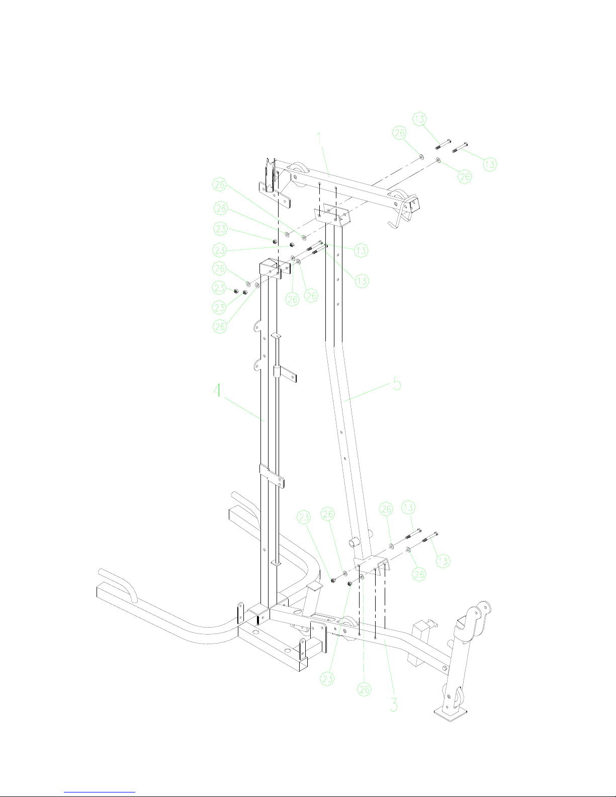
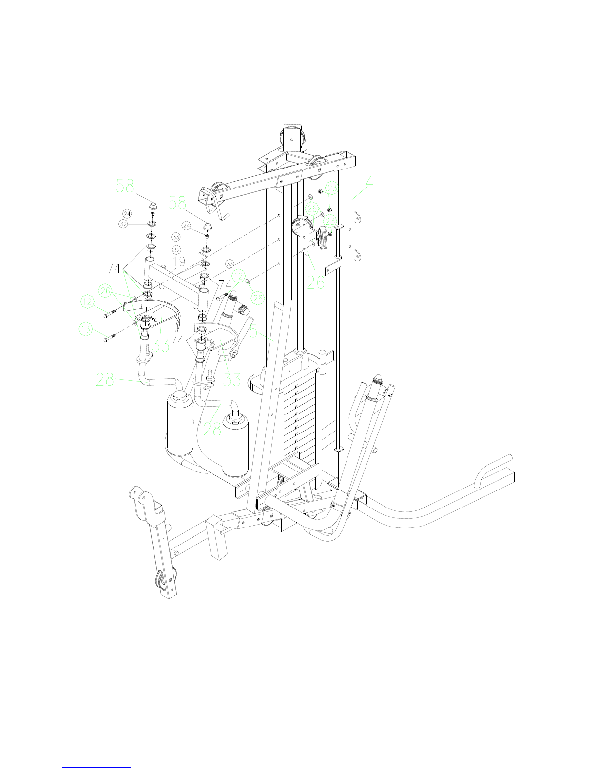
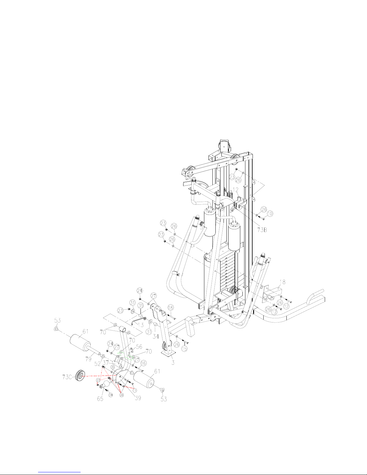
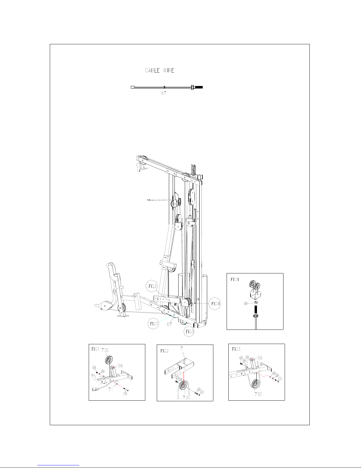
Assembling steps-----------------------------------------------------2-15
Exploded view------------------------------------------------------16-17
Partslist--------------------------------------------------------------18-22
DailyMaintenance------------------------------------------------------22
Warning
1. Beforeexercise,pleasechecktomakesureall boltsaretightenedand handlebarweldsare
intact.
2. Wear appropriatefootwear during work out. Do notflip thehandlebarsduring exercise.
3. Whenweightstack,suspenderor otherpartsarecaught,askanotherperson shelptoavoidthe
sudden drop of weightstack.
4. Donotdistortthecable whenyou adjustitslength(tightness). Afterusing for aperiod of time,
youshouldcheckifcable skinhasworn outor thecableisbadlystretched,contact the
servicemanto repairor replace assoon asyou find problems.
5. Donotdrop weightstacksall of asuddentoavoiddamageandinjury.You shouldalwayslower
theweightstacksslowly.
6. Donotinserthand and otherpartsof thebodybetween/underweightstacksandothermoving
partsto avoidinjury.
7. Children under 16 should exerciseunder adult sguidance.
8. People havespecial conditions(for example,agedor diseased) shouldalwaysconsult your
physician beforestarting exercise.

2
Assembling steps
1. Removeall partsoutof boxesand place around area of installation! Place boltpacksin frontof
thearea whereyou wantthegym.
2. Place part(2)indesiredposition, thenconnect part(3) withpart(4) using bolts
(M10x75mm)(13), bolts(M10x80mm)(14), washers(26)and locknuts(23). Slidepulleylimiting
board (17) throughtheleaderII (30), connectingtoverticaltube(4) withhexbolts(M6x20mm)(1)
and washer(8) (25).

3
3. Connectbackresttube(5)toseattube(3) withbolts(M10x75mm)(13),washers(26) and
locknuts(23). Connect tube(1) tobackresttube(5) and vertical tube(4) with(M10x75mm)(13) ,
washers(26) and locknuts(23).

4
4. Insertleaders(10) intotheorientedholeson thebottomofthecurlbasetube(2),inturn, slide
coverbumpers(51), rubberweightstack(48) and plastictop plate (46). Mountleadertop tube(6)
totheleader(10) bywashers(26) and bolts(M10x20mm)(5). Connect exercisechartflip(76),
leadertop tube(6) and Labpull downtop tube(1) withbolts(M10x75mm)(13), washers(26)
and locknuts(23).
Attach shrouds(9) tothecurlbasetube(2) with washers(26) and bolts(M10x16mm)(4). Attach
handlebar tube(11) to thevertical tube(4) with washer (26) and bolt (M10x30mm)(7).
Attachplastic briquetting(46) totheleader(22) withbolt(M8x70mm)(8),washers(8)(25) and
locknut(M8)(22).

5
5. Connectbackresttube(5) andchest-extension rotating frame(7)throughtherotating bearing
(25), tightenwithHexangularfloriatedbolt(M8*10mm)(30). Securebearing bases(38), washers
(26) and bolts(M10x25mm)(6).
Attachchest-extension handlebars(8R&L)tothechest-extension rotating frame(7), whichwas
alreadyattachedtobackresttube(5) instep4, withwashers(26) and bolt (M10x30mm)(7). Slide
crossedbearing covers(29) tothechest-extension handlebars(8R&L), tightenwithnutcanopy(58).
Connect pulling bar(27R&L)and crossedbearing cover(29) through limiting bushing (31), bolt
(M12x120mm)(19), powdermetallurgybushing (74) ,flatwasher(33),dishwasher(32) and locknut
(24).
Attachchest-extension handlebars(8L&R) tothefixing tube(50) withbolt(M10x75)(13) and
locknut(M10)(23).

6
6.Connect thechest-extension frame (19),backresttube(5) and pulleyfixing frame (26) withbolts
(M10x70mm)(12), bolts(M10x75mm)(13), washers(26)and locknuts(23). Fit chest-extension arm
(28), chest-extensionadjusting board (33) tochest-extension frame(19)withlocknut(24) and
powder metallurgybushing (74),flat washer(12)(33),dish washer(12)(32),nutcanopy(M12)(58).

7
7. Attachorientedhook(13) and zincbushing(34) separate ring(35) toseattube(3) withbolt
(M10x90mm)(15), washer(26), flat washer(31) and locknut(23). Attachrubbercushion (56) to
theback of leg-kicking frame(39).
Connect seat tube(3) and leg-kicking frame(39) withpowdermetallurgybushing (70), bolt
(M12x80mm)(18),washers(27) and locknut(24). Attach leg-extension connectingcover (37) to
leg-kicking frame(39) withpowdermetallurgybushing (70),bolt (M12x70mm)(16), washers
(27) and locknut(24). Slidetube(79) through theleg-extension connecting cover(37), slidethe
bolsters(61) ontobothend ofthetube,blockwithleg-kickingsofaholecovers(52)and plastic
briquetting (53).
Attachbackrestadjusting bushing (18) tobackresttube(5) withbolt (M10x70mm)(12), washers
(26) and locknut(23). Connect narrowsingle pulleyfork (12),pulley(73B) and pulleylimiting
board (17) with bolt (M10x55mm) (10), washers(26) and locknut(23).

8
8. Wirecircling way:
Cablestobeinstalledinordercable(67)first,cable (63)second, cable(64) third,cable(66) fourth
and cable (65) last.Viewfollowing 5 pagesfor figurediagrams.

9
The1ST wire: (refer to thefollowing illustration)

10
The2nd wire: (refer to thefollowing illustration)

11
The3rd wire: (refer to thefollowing illustration)

12
The4th wire: (refer to thefollowing illustration)

13
The5th wire: (refer to thefollowing illustration)

14
9. Attach handlebar tube(11) to theparallel bar with washer (26) and bolt (M10x20mm)(5). Attach
parallelbar(20) tothevertical tube(4) withbolts(M10x75mm)(13), washers(26) and locknuts
(23).
Attach armcushion (44) to theparallelbar (20) with washers(25) and bolts(M8x70mm)(8).
Connect backrestcushion (41) and backrestadjusting tube(24) withwashers(25) and bolts
(M8x30mm)(3),theninsertbackrestadjusting tube(24) intobackrestadjusting bushing (18),
and lock itwithT-shaped adjustable pin (68).
Connect seatadjusting tube(35) andseat cushion (42)withwashers(25) and bolts
(M8x30mm)(3), theninsertseat adjusting tube(35) intothesidebushing on seattube(3), and
lock it withT-shapedadjustable pin (68).
Slidetube(79) through theleg-kicking adjusting tube(36), slidethebolsters(61) ontobothend
of thetube,lockwithleg-kicking sofahole covers(52) and plastic briquetting(53). Insert
leg-kicking adjustingtube(36) intothefrontbushing on seat tube(3), lockitwithT-shaped
adjustable pin (68).

15
10. Attachbackrestcushion (43)totheverticaltube(4) withwashers(25) and bolts
(M8x20mm)(2).

16
EXPLODEDVIEW

17
Parts List I

18
Parts List II

19
Parts List III
Table of contents
Other Orbit Home Gym manuals