Oreka O2 User manual

USER MANUAL
TRAINING
THE PERFECT ALLY FOR
INTENSIVE AND REAL
TRAINING
TRAINING
Thank you for purchasing our OREKA O2 !
To use our product safely, please read this manual carefullybeforehand.
In case you need more information, please visit our website, FAQs or
contact us in: [email protected]
For any other consult, please contact:
OREKA TRAINING, S.L.
CIF: B 75150219.
Address: Oreka Training SL. Poligono Egiburuberri 3, 20100 Errenteria,
Gipuzkoa. Spain.
NOTE: The company reserves the right to modify the design ofthe
product or its specifications to improve quality.
PLEASE KEEP THIS MANUAL SAFE AFTER READING

I
N
D
E
X
1
.
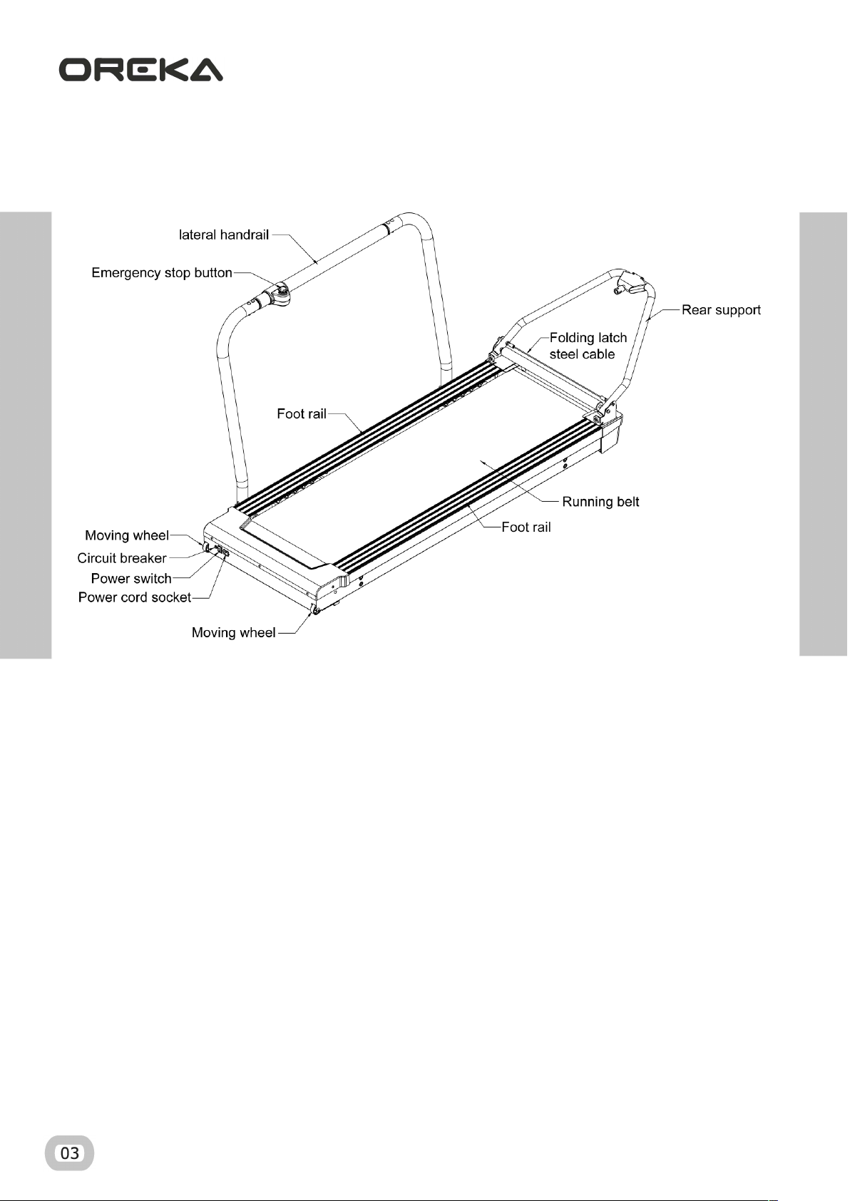
GENERAL VIEW OF THE PRODUCT
...........................................................................
3
2
.
TRAINER USAGE NOTES
..............................................................................................
4
3
.
ASSEMBL Y INSTRUCTIONS
........................................................................................
7
4
.
RAIL ASSEMBL
Y ..................................................................................................... 9
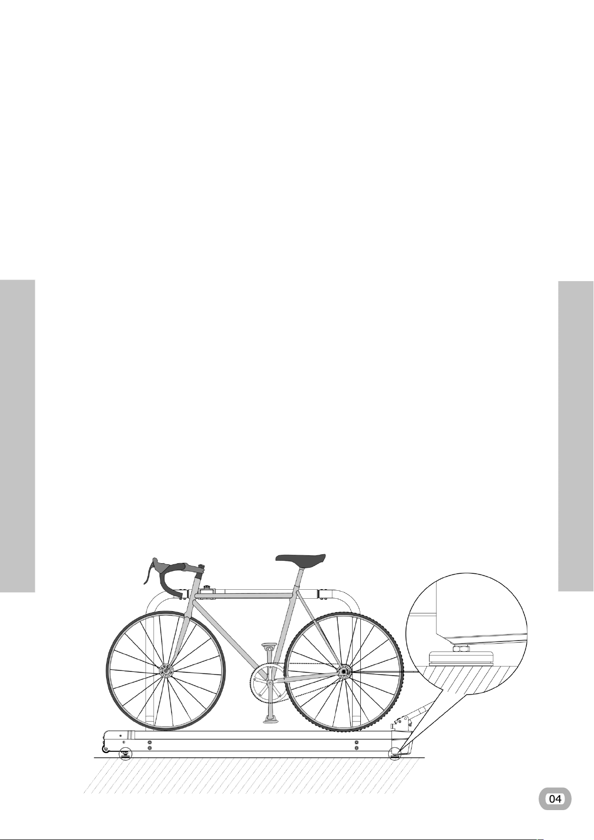
5.PLACING THE BICYCLE ON THE TRAINER ......................................................... 13
6
.
BAND ADJUSTMENT ............................................................................................... 15
7.
BEFORE YOUR FIRST SESSION ........................................................................... 18
8
.
EXEMPTION FROM LIABILITY ............................................................................... 19
9
.
WARRANTY ............................................................................................................. 20
10
.
TECHNICAL ASSISTANCE ...................................................................................... 20
PAIRING TO A SIMULATOR ................................................................................... 18
11
.
bxybxz
.bx.
Dqmbxvm
mmm.
TRAINING
•
•
fi
O
E
A
AININ
•
•
•
•
•
•
8
z
•
IA
ff
•
I
-
D
•
flflF

•qOEA´
I
•
D
OEAAININ
•B
A
qOEAAININ
•
I
TRAINING

•
•
A
•
A
(
)
B
•
I
O
E
A
AININ
•Dp
OEAAININ
•D
A
O
E
A
AININ
•I
OEAAININ(@)
•F
I
z
N
z
3
MB
Y
07
TRAINING
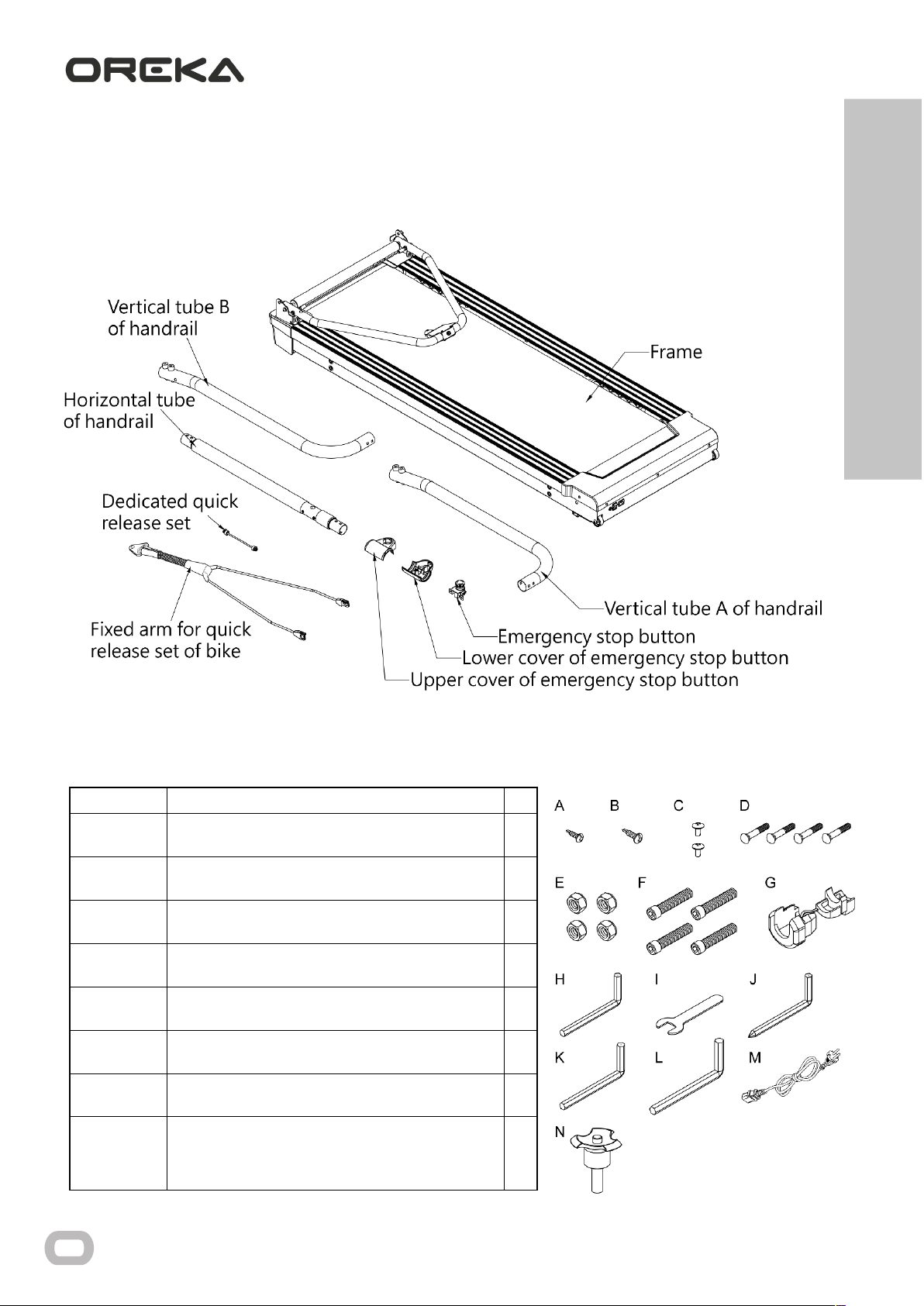
a)
isassembled
main
body
b)
isassembled
accesories
ELEMENT Description Qty
A Auto thread Screw Ø3x12 1
B Auto thread Screw Ø4x15 1
C Screw M6xP1.0x10 2
D Screw M8xP1.25x60 (thread lenght 25 mm) 4
E Nylon nut dry screw M8xP1.25 4
F Hexagonal Screw M10xP1.5x85 4
G Plastic plug 6P-4 2
H
Hexagon wrench 5x28x75mm ( there’s a hole in
the middle) 1
I Open spanner 13mm 1
J Hexagon wrench 5x36x120mm 1
K Hexagon wrench 8x36x98mm 1
L Hexagon wrench 10x65x120mm 1
M Power cord 1
N Quick Release Pin 1
08
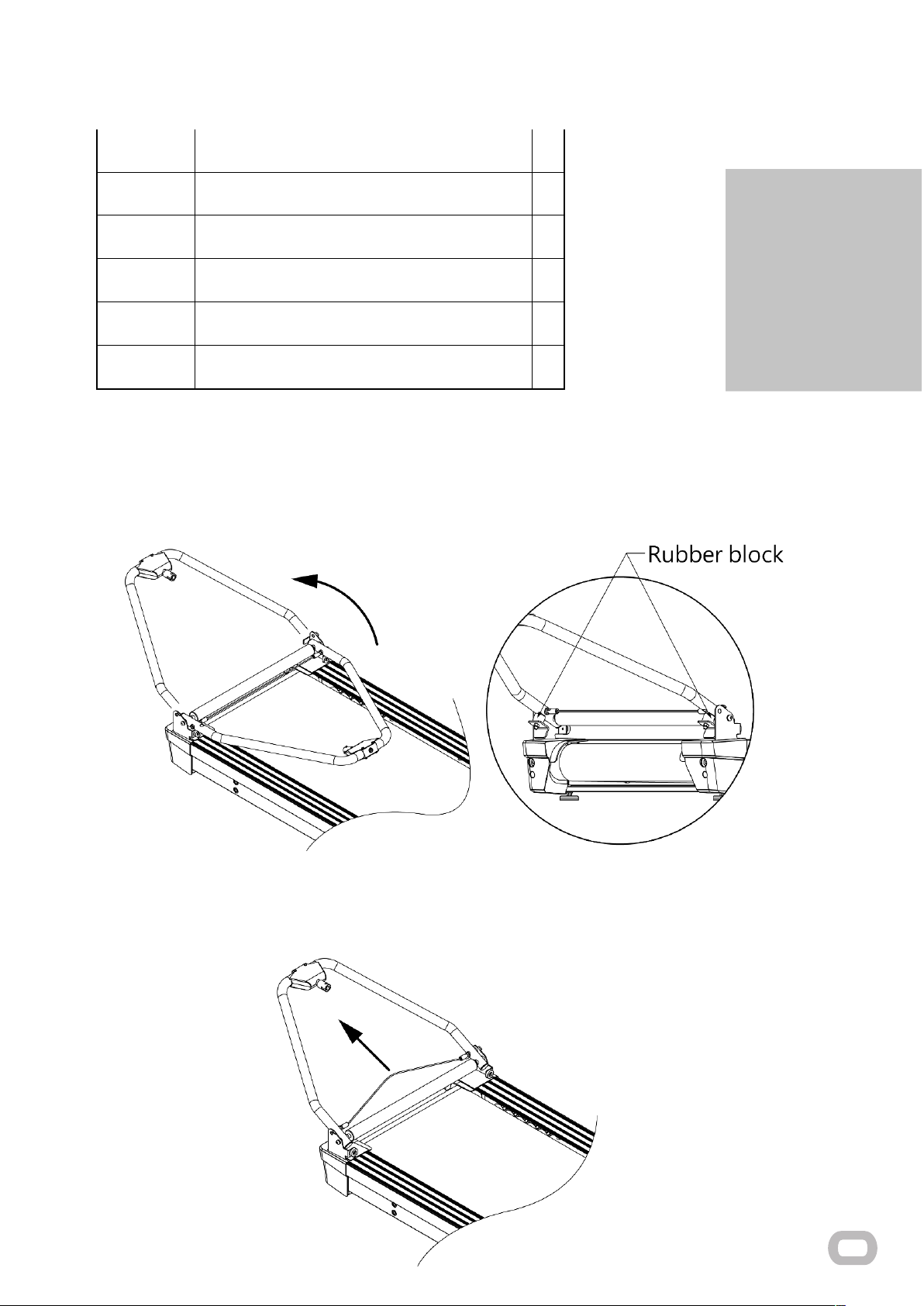
c) Rear support fold
i. Rear support placing
The rear support rotates upward until the bolt automatically locates the fixed hole.
ii. Fold
P
ull the steel cable upward so that the bolt leave the hole and rotate the lash downward.

4
.RAIL ASSE
MB
L
Y
TRAINING
S
tep
1
1.
The emer
g
ency button is fixed to the hori
z
ontal tube of the rail with the
C
screws. The connection cables
enter throu
g
h the notch on the hori
z
ontal tube and should exit throu
g
h one of its extremities.
2.
The upper and lower casin
g
s of the emer
g
ency button should be fixed with the screws
A,B
and
C
.
B
e
careful to not to nip the cable while screwin
g
the casin
g
s.
S
tep
2
The emergency button cable should be inserted through the interior of the vertical tube of the rail. It should
be fastened through the inferior part. Then, the vertical tube A and B should be fixed to the horizontal tube.
Finally, the D screws are placed on the superior part and the E nuts on the inferior part (it is very important
that everything is properly fixed to avoid backlash and to assure that the assemble is properly tighten)
Other manuals for O2
2
Table of contents
Other Oreka Fitness Equipment manuals


Popular Fitness Equipment manuals by other brands


G-FITNESS
G-FITNESS AIR ROWER user manual

CAPITAL SPORTS
CAPITAL SPORTS Dominate Edition 10028796 manual

Martin System
Martin System TT4FK user guide

CIRCLE FITNESS
CIRCLE FITNESS E7 owner's manual

G-FITNESS
G-FITNESS TZ-6017 user manual

Accelerated Care Plus
Accelerated Care Plus OMNISTIM FX2 CYCLE/WALK user manual


