manuals.online logo
Brands
  1. Home
  2. •
  3. Brands
  4. •
  5. Oriental motor
  6. •
  7. Fan
  8. •
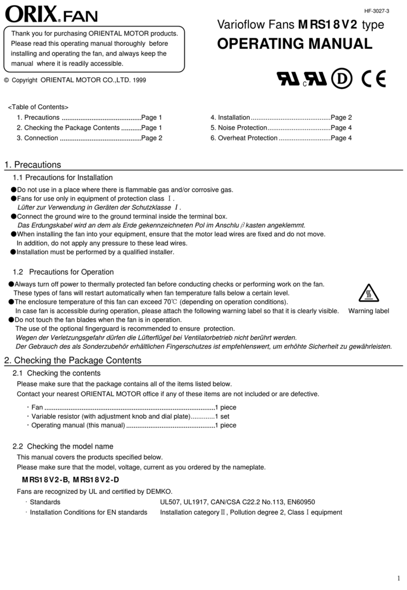
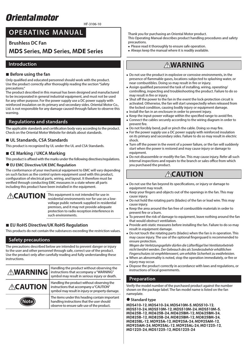
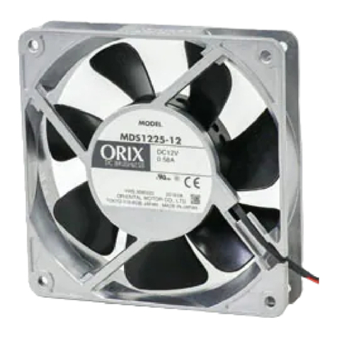
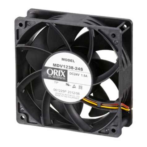
  9. Oriental motor MRE Series User manual

Oriental motor MRE Series User manual

1
Introduction
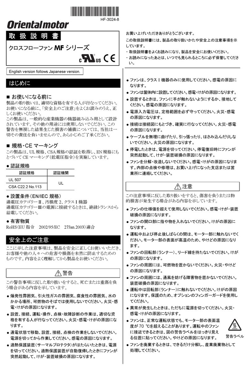
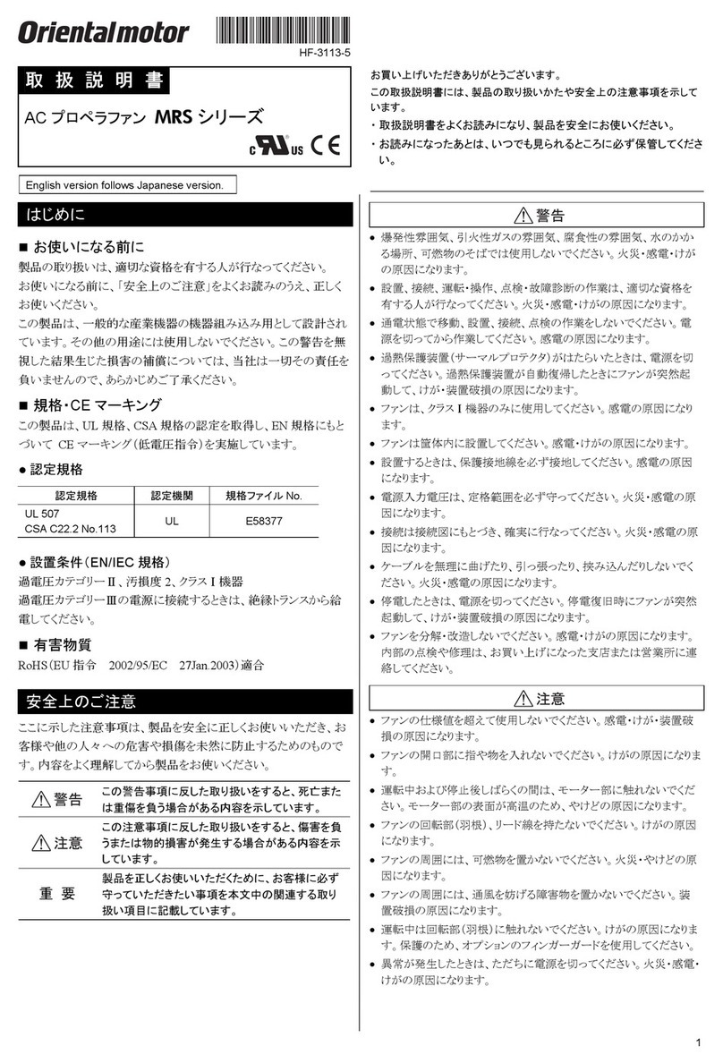
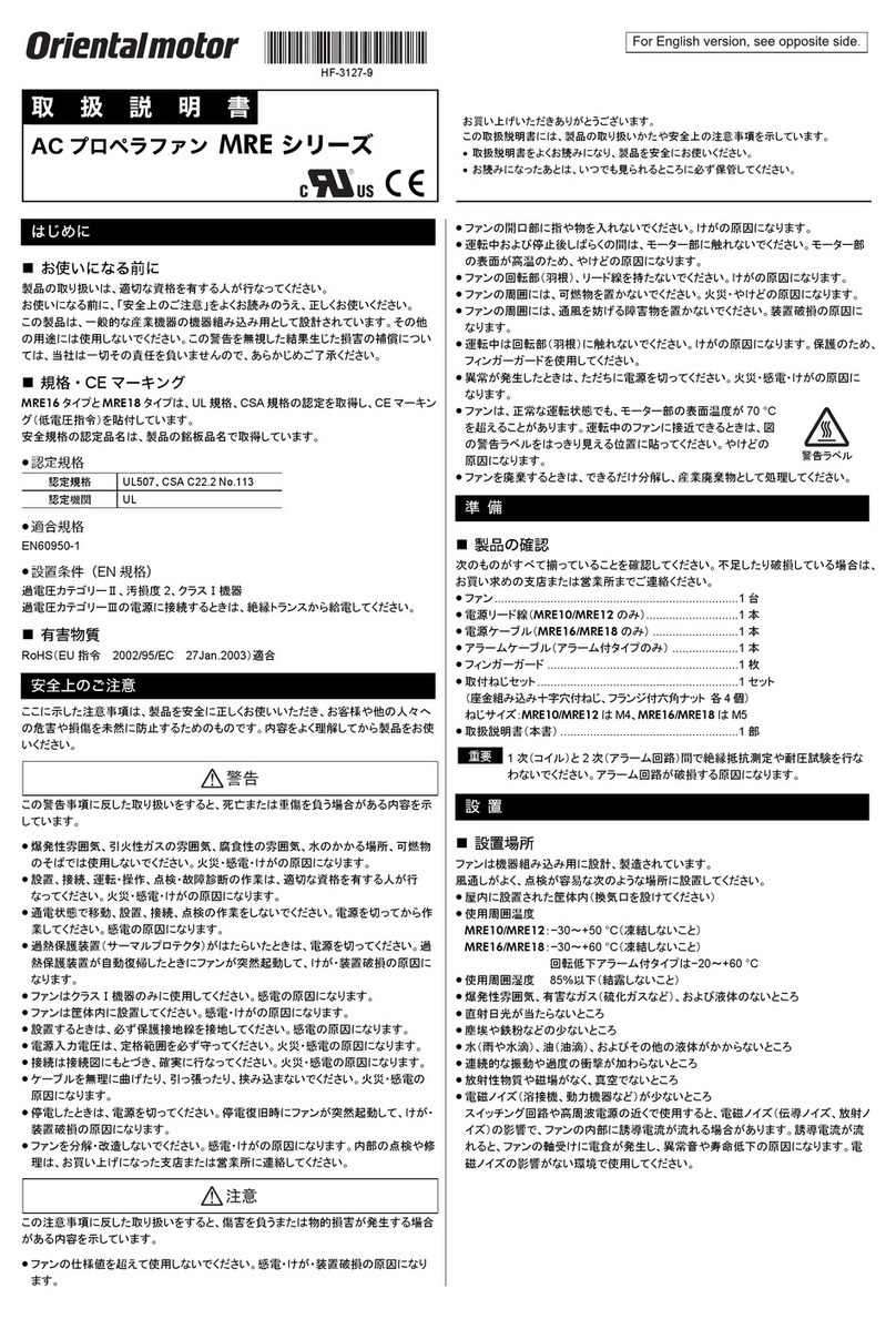
 Before use
Only qualied personnel of electrical and mechanical engineering should work with
the product. Use the product correctly after thoroughly reading the section“Safety
precautions.”In addition, be sure to observe the contents described in warning,
caution, and note in this manual. The product described in this manual is designed and
manufactured to be incorporated in general industrial equipment. Do not use for any other
purpose. Oriental Motor Co., Ltd. is not responsible for any compensation for any damage
caused through failure to observe this warning.
Safety precautions
The precautions described below are intended to ensure the safe and correct use of the
product, and to prevent the customer and others from exposure to the risk of injury. Use
the product only after carefully reading and fully understanding these instructions.
WARNING
Handling the product without observing the instructions
that accompany a“WARNING”symbol may result in serious
injury or death.
CAUTION
Handling the product without observing the instructions
that accompany a“CAUTION”symbol may result in injury or
property damage.
Note
The items under this heading contain important handling
instructions that the user should observe to ensure safe use
of the product.
Explanation of
graphic symbols
: Indicates“prohibited”actions that must not be performed.
: Indicates“compulsory”actions that must be performed.
WARNING
Do not use the product in explosive or corrosive environments, in the
presence of ammable gases, in places subjected to splashing water, or near
combustibles. Doing so may result in re, electric shock or injury.
Do not transport, install, connect, or inspect the product while the power is
supplied. Always turn o the power before carrying out these operations. This
may result in electric shock or injury.
Do not forcibly bend, pull or pinch the cable or lead wire. Doing so may result
in re or electric shock.
Do not touch the connection terminals of the capacitor immediately after the
power is turned o (for a period of 30 seconds). The residual voltage may cause
electric shock.
Do not disassemble or modify the fan. Doing so may cause electric shock, injury
or damage to equipment. Refer all such internal inspections and repairs to the
branch or sales oce from which you purchased the product.
Only qualied and educated personnel should be allowed to perform
installation, connection, operation and inspection/troubleshooting of the
product. Handling by unqualied and uneducated personnel may result in re,
electric shock or injury.
Turn o the power in the event the overheat protection device (thermal
protector) is triggered. Failure to do so may result in injury or damage to
equipment, since the fan will start abruptly when the overheat protection
device (thermal protector) is automatically reset.
The fan is ClassⅠequipment. Install the fan so as to avoid contact with hands,
or ground it to prevent the risk of electric shock.
Be sure to keep the input power voltage within the specied range. Failure to
do so may result in re or electric shock.
Perform connections securely according to the connection diagram. Failure to
do so may result in re or electric shock.
Insulate the connection terminals of the included capacitor using the included
capacitor cap. Failure to do so may result in electric shock.
Turn o the power in the event of a power failure. Otherwise, the fan will start
unexpectedly when the power is restored. This may cause injury or damage to
equipment.
CAUTION
Do not use the fan beyond its specications, or electric shock, injury or damage
to equipment may result.
Do not conduct the insulation resistance measurement or dielectric strength
test between the lead wires of fan windings and the lead wires of the alarm.
Doing so may cause damage to the alarm circuit.
Keep your ngers and objects out of the openings in the fan. This may cause
injury.
Do not touch the motor part while operating or immediately after stopping.
The surface is hot and it may cause a skin burn(s).
Do not lift the product by holding the rotating part (blades), cable or lead wire
of the fan. Doing so may cause injury.
CAUTION
Keep the area around the fan free of combustible materials. Failure to do so
may result in re or a skin burn(s).
Do not leave anything around the fan that would obstruct ventilation. Doing so
may result in damage to equipment.
Do not touch the rotating part (blades) when the fan is in operation. Doing
so may cause injury. The use of the nger guard is recommended to ensure
protection.
Immediately when trouble has occurred, stop operation and turn o the power
supply. Failure to do so may result in re, electric shock or injury.
Securely install the fan in an enclosure. Failure to do so may result in injury or
damage to equipment.
The motor surface temperature of the fan may exceed 70 °C (158 °F)
even under normal operating conditions. If the operator is allowed to
approach the fan that is operating, attach a warning label as shown
in the gure in a conspicuous position. Failure to do so may result in
a skin burn(s).
Warning
label
Checking the product
 Package contents
Verify that the items listed below are included. Report any missing or damaged items to
the branch or sales oce from which you purchased the product.
MRE16, MRE18, MRE20 MRE25
□Fan................................................1 unit
□Power supply cable................1 piece
□Alarm cable...............................1 piece
(For alarm type fans only)
□OPERATING MANUAL
(this document).......................1 copy
□Fan................................................1 unit
□Capacitor ..................................1 piece
□Capacitor cap...........................1 piece
□OPERATING MANUAL
(this document).......................1 copy
Included with single-phase fans only
Items included with fan kit products
□Finger guard.............................1 piece
□Mounting screw......................1 set
(Cross-recessed pan head screws with captive washer, hexagonal nuts with ange
4 pieces each)
 Checking the model name
Verify the model name of the purchased product against the model shown on the package
label. Check the fan model against the model name shown on the nameplate. Tell us the
model name, product serial number, and manufacturing date when you contact us.
zFan model
MRE 18 - B B H
① ② ③ ④⑤⑥
①Series name MRE:MRE Series
②Frame size 16: 160 mm (6.30 in.) 18: 180 mm (7.09 in.)
20: 200 mm (7.87 in.) 25: 250 mm (9.84 in.)
③Power supply
voltage
B: Single-phase 100/110/115 VAC D: Single-phase 200/230 VAC
E: Single-phase 220/230/240 VAC T: Three-phase 200/220/230 VAC
JA: Single-phase 100 VAC UA: Single-phase 110/115 VAC
JC: Single-phase 200 VAC EC: Single-phase 220/230 VAC
JS: Three-phase200 VAC ES: Three-phase 220/230 VAC
④Additional
function
B: Low-speed alarm, contact alarm type
(Normal operation: Contact ON)
A: Low-speed alarm, contact alarm type
(Normal operation: Contact OFF)
M: Low-speed alarm, electronic alarm type
Blank: Non-alarm type
⑤Connection
type H: With extension cable Blank: Lead wires
⑥Reference number
zFan kit model
T- MRE18-BBH - G
Finger guard, mounting screws
Fan model
Fan kit
HF-3172
OPERATING MANUAL Thank you for purchasing an Oriental Motor product.
This Operating Manual describes product handling procedures and safety precautions.
Please read it thoroughly to ensure safe operation.
Always keep the manual where it is readily available.
AC Axial Flow Fans
MRE Series
2
Installation
 Installation location
Install the product in the following location that provides easy access for inspection. The
location must also satisfy the following conditions:
Inside an enclosure that is installed indoors
Operating ambient temperature: −30 to +60 °C [−22 to +140 °F] (non-freezing)
Operating ambient humidity: 85 % or less (non-condensing)
Area free from an explosive atmosphere or toxic gas (such as sulfuric gas) or liquid
Area not exposed to direct sun
Area free of excessive amount dust, iron particles or the like
Area not subject to splashing water (storms, water droplets), oil (oil droplets) or other
liquids
Area not subject to continuous vibration or excessive shocks
Area free of radioactive materials, magnetic elds or vacuum
Area free of excessive electromagnetic noise (from welders, power machinery, etc.)
When using a fan near a switching circuit or high-frequency power supply, the induced
current may ow inside the fan due to electromagnetic noise (conductive noise, radiative
noise). If the induced current ows, the electric corrosion is caused in the bearings of the
fan. As a result, it may generate the noise or shorten the service life of the products. Use
the fan in the environment that the electromagnetic noise does not cause.
 Installation method
Install the fan onto an appropriate at metal plate having excellent vibration resistance
and heat conductivity.
Drill mounting holes in equipment, and secure the fan using screws.
Mounting screws are included with the fan kit products.
For directions of the air ow and blades rotation, see the indications on the side of the
fan frame.
Screw size: M5
Tightening torque: 1.2 N·m (10.6 lb-in)
Mounting plate
Fan
When nger guards are installed
Finger guard∗
∗A nger guard is included with the fan kit product.
If another nger guard is needed, purchase it separately.
Connection
Insulate all connections such as connecting sections between the fan lead wires and the
power supply connections, and the capacitor connections.
 Connecting Protective Earth Terminal
Ground using the Protective Earth Terminal of the fan.
Grounding
Applicable crimp terminal:
Insulated round crimp terminal
Terminal screw size: M4
Tightening torque: 1.0 to 1.3 N·m (8.8 to 11.5 lb-in)
Applicable lead wire: AWG18 (0.75 mm2) or thicker
Ø4.1 (0.16)
or more
[ Unit: mm (in.) ]
4.8 (0.19) or less
9.5 (0.37)
or less
Note Be sure to use the screw for protective earth attached on the product.
 Connecting the power supply
Connect the power supply cable and the alarm cable to the power input connector and
the alarm connector, respectively. (Except for MRE25)
The gure shows the MRE16 and MRE18 types. For the MRE20 types, connect the power
supply cable and the alarm cable to the cable connector that is come out of the fan frame.
Alarm connector
∗
Alarm cable∗
Power supply cable
To power supply
∗ For alarm type fans only
Power input connector
To customer's circuit
zConnection diagram
Check the fan model name used before connecting.
Single-phase input
MRE16, MRE18
Power supply cable Lead wire size: AWG18 (0.75 mm2)
Alarm cable Lead wire size: AWG20 (0.5 mm2)
L
N
Power
supply
White
Black
Grounding
Alarm
output∗Blue
Orange
∗For alarm type fans only
Rotation
direction
Air ow
MRE25
Power supply lead wire size: AWG20 (0.5 mm2)
Alarm lead wire size: AWG22 (0.3 mm2)
L
N
Power
supply
White
Black
Red
Orange
Blue
Alarm
output∗
Grounding
∗ For alarm type fans only
Rotation
direction
Air ow
3
zConnecting the capacitor
When crimp terminals are used, use the FASTON
terminals 187 Series (TE Connectivity).
Use the included capacitor cap to insulate the capacitor
terminal connection.
Capacitor
187 series
Capacitor
cap
Ø4.3 mm (Ø0.169 in.)
The capacitor has four terminals that are
internally connected as shown in the
gure.
Use a screw of M4 (not included) to install the capacitor securely.
Tightening torque: 1.0 N·m (8.8 lb-in)
重 要For lead wire connection, use one lead wire for each individual terminal.
Three-phase input
MRE16, MRE18, MRE20, MRE25
The gure shows the MRE16 and MRE18 types.
Power supply cable Lead wire size: AWG18 (0.75 mm2)
AWG20 (0.5 mm2) for MRE25
Alarm cable Lead wire size: AWG20 (0.5 mm2)
AWG22 (0.3 mm2) for MRE25
Grounding
Alarm
output∗Blue
Orange
Power
supply
White
Black
Red
∗
For alarm type fans only
L1 (R)
L2 (S)
L3 (T)
Rotation
direction
Air ow
 Connecting the alarm output
The alarm type fans are equipped with the low-speed alarm.
If the fan speed falls to 1800±300 r/min or lower, the alarm signal is output.
The contact alarm type and the electronic alarm type are available for the low-speed alarm
fans.
Note The alarm circuit is not equipped with a delay function. To avoid an alarm
detection when the fan starts rotating or stops, a delay function is required
externally. The delay time should be at least ten seconds.
zLow-speed alarm, contact alarm type (Relay output)
There are two types of the contact alarm type:“Normal operation: Contact ON”and “Normal
operation: Contact OFF.”
Enter the code representing the power supply voltage in the box () within the model
name.
Model
MRE16-BH
MRE18-BH
MRE20-TBH
MRE25-B
MRE16-AH
MRE18-AH
Output
status
Normal operation: Contact ON
Alarm output: Contact OFF
Normal operation: Contact OFF
Alarm output: Contact ON
Connection
diagram
R
Orange
Blue
0 V
Customer's circuit
Fan
Contact capacity: Resistive load 10 VA max. (100 V max., 0.5 A max.)
Minimum load: 5 V, 1 mA
(Design your alarm circuit to operate at 0.5 mA or less.)
zLow-speed alarm, electronic alarm type (Open-collector output)
Enter the code representing the power supply voltage in the box () within the model
name.
Model
MRE16-MH
MRE18-MH
MRE20-TMH
Output
status
Normal operation: L level (Internal transistor ON)
Alarm output: H level (Internal transistor OFF)
Connection
diagram
R
Orange
Blue
0 V
Customer's circuitFan
15 mA
or less
30 VDC or less
Maximum output voltage: 30 VDC
Maximum output current: 15 mA
Output saturated voltage: 0.4 V or less
Operation
The fan rotates when the power supply is turned on.
For protection against electric shock, do not turn on the power supply until the wiring is
complete.
Note Make sure that the motor case temperature does not exceed 90 °C (194 °F)
when operating the fan. Operating the fan in a state where the motor case
temperature exceeds 90 °C (194 °F) deteriorates the windings and ball bearings
of the motor, causing the lifetime to shorten. Measure to check the motor case
temperature using a thermometer, thermo tape or thermocouple.
zWhen using the fan with an inverter (Three-phase input only)
When using the fan in combination with an inverter, use it by setting the inverter
frequency to 60 Hz or less.
The inverter which input voltage exceeds 240 VAC cannot be used. The insulation of the
fan motor windings may deteriorate, causing damage to the fan.
Number of fan poles: 2 poles
A resonance phenomenon may occur depending on the setting frequency. If the
resonance phenomenon occurred, use the product with avoiding the resonance points.
Note In the case of the alarm type fans, the low-speed alarm may operate if an
inverter is used at low speeds.
Locked rotor burnout protection
The fan is equipped with a function of burning protection for locked-rotor state.
 Thermal protection
The fan motor contains an automatic return type thermal protector in the motor windings.
When the motor internal temperature exceeds the specied value, the thermal protector is
activated to stop the fan. Always turn o the power before performing inspections.
Thermal protector activation range:
Power is turned o at 120±5 °C (248±9 °F)
Power is turned back on at 77±15 °C (170±27 °F)
Inspection and maintenance
 Inspection
It is recommended that periodic inspections for the items listed below are conducted after
each operation.
If an abnormal condition is noted, discontinue any use and contact your nearest Oriental
Motor sales oce.
zInspection item
Check if any of the screws of the fan and peripheral equipment is loose.
Check if the fan generates unusual noises.
 Warranty
Check on the Oriental Motor Website for the product warranty.
 Disposal
Dispose the product correctly in accordance with laws and regulations, or instructions of
local governments.
Unauthorized reproduction or copying of all or part of this manual is prohibited.
Oriental Motor shall not be liable whatsoever for any problems relating to industrial
property rights arising from use of any information, circuit, equipment or device
provided or referenced in this manual.
Characteristics, specications and dimensions are subject to change without notice.
While we make every eort to oer accurate information in the manual, we welcome
your input. Should you nd unclear descriptions, errors or omissions, please contact the
nearest oce.
and are registered trademarks or trademarks of Oriental Motor
Co., Ltd., in Japan and other countries.
© Copyright ORIENTAL MOTOR CO., LTD. 2020
Published in November 2020
4
T
echnical Support Tel:800-468-3982
8:30am EST to 5:00pm PST
(M-F)
www
.orientalmotor.com
Schiessstraße 44, 40549 Düsseldor
f, Germany
T
echnical Support Tel:00 800/22 55 66 22
www
.orientalmotor.de
T
el:+44-1256347090
www
.oriental-motor.co.uk
T
el:+33-1 47 86 97 50
www
.orientalmotor.fr
T
el:+39-02-93906347
www
.orientalmotor.it
• Please contact your nearest Oriental Motor oce for further information.
4-8-1Higashiueno
,Taito-ku,Tokyo 110-8536
Japan
T
el:+81-3-6744-0361
www
.orientalmotor.co.jp
Tel:0800-060708
www.orientalmotor.com.tw
Singapore
Tel:1800-842-0280
www.orientalmotor.com.sg
Tel:1800-806-161
www.orientalmotor.com.my
Korea
Tel:080-777-2042
www.inaom.co.kr
Tel:1800-888-881
www.orientalmotor.co.th
Tel:400-820-6516
www.orientalmotor.com.cn
Tel:1800-120-1995 (For English)
1800-121-4149 (For Hindi)
www.orientalmotor.co.in
Specications
Check on the Oriental Motor Website for the product specications.
General specications
Operating
environment
Ambient
temperature −30 to +60 °C [−22 to +140 °F] (non-freezing)
Ambient
humidity 85% or less (non-condensing)
Storage
environment
Shipping
environment
Ambient
temperature −40 to +70°C [−40 to +158°F] (non-freezing)
Ambient
humidity 85% or less (non-condensing)
Degree of protection IP00
Regulations and standard
 UL Standards and CSA Standards
This product is recognized by UL under the UL and CSA standards.
Applicable Standards Certication Body / File No.
UL 507 UL / E58377
CSA C22.2 No.113
Thermal class UL/CSA Standards:105(A)
 CE Marking
These products are axed with the CE Marking under the Directives shown below.
Model Type Low Voltage
Directive EMC Directive Ecodesign Directive
MRE16
MRE18
MRE20
Non-alarm type ○ - -
Alarm type ○ ○ -
MRE25
Non-alarm type ○ - MRE25-JC,
MRE25-EC
Alarm type ○ ○ MRE25-JCB,
MRE25-ECB
zLow Voltage Directive
Applications standards
EN 62368-1
Installation conditions (For EN standard)
Overvoltage categoryⅡ, Pollution degree 2, ClassⅠequipment
If the specied values of the overvoltage category Ⅲis required based on the equipment,
supply the rated voltage to the fan via an isolation transformer.
zEMC Directive (Alarm type fans only)
Applications standards
EMI: EN 61000-6-4 EMS: EN 61000-6-2
zEcodesign Directive
(MRE25-JC, MRE25-EC, MRE25-JCB, MRE25-ECB only)
Regulations
COMMISSION REGULATION (EU) No 327/2011
Product Information
Actual Req.2015 Actual Req.2015
(1) Overall
eciency ηes (%) 31.5 28 33.6 28
(2) Measurement
category A
(3) Eciency
category Static
(4) Eciency grade N 43.5 40 45.6 40
(5) Variable speed
drive No
(6) Year of
manufacture
The year of manufacture is specied on the product's
nameplate.
(7) Manufacturer ORIENTAL MOTOR CO., LTD.
4-8-1 Higashiueno, Taito-ku, Tokyo 110-8536, Japan
(8) Product’s model
number
MRE25-JC,
MRE25-JCB
MRE25-EC,
MRE25-ECB
(9) Power input Pe (kW) 0.126 0.125
Air ow qv (m³/h) 893 924
(10) Speed rpm 3036 3130
(11) Specic ratio 1
(12) Recycling/
disposal
Dispose the product correctly in accordance
with laws and regulations, or instructions of local
governments.
(13) Maintenance Information on maintenance is provided in the
operating manual.
(14) Additional items No attachments
 Republic of Korea, Radio Waves Act (Alarm type fans
only)
KC Mark is axed to this product under the Radio Waves Act, the republic of Korea.
 RoHS Directive
The products do not contain the substances exceeding the restriction values of RoHS
Directive (2011/65/EU).

This manual suits for next models

19

Other Oriental motor Fan manuals

Oriental motor MRS Series User manual

Oriental motor

Oriental motor MRS Series User manual

Oriental motor MD Series User manual

Oriental motor

Oriental motor MD Series User manual

Oriental motor MRS16V User manual

Oriental motor

Oriental motor MRS16V User manual

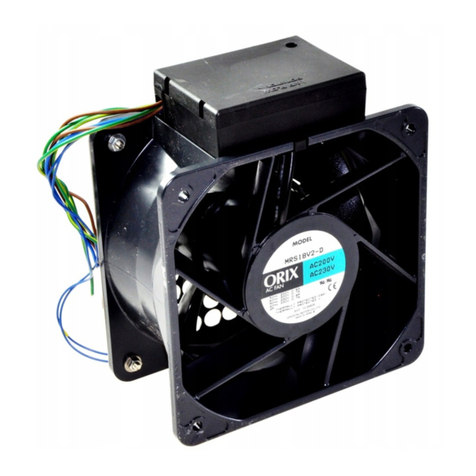
Oriental motor ORIX MRS18V2 User manual

Oriental motor

Oriental motor ORIX MRS18V2 User manual

Oriental motor MDS Series User manual

Oriental motor

Oriental motor MDS Series User manual

Oriental motor MDS Series User manual

Oriental motor

Oriental motor MDS Series User manual

Oriental motor MU Series User manual

Oriental motor

Oriental motor MU Series User manual

Oriental motor MDS Series User manual

Oriental motor

Oriental motor MDS Series User manual

Oriental motor MD Series User manual

Oriental motor

Oriental motor MD Series User manual

Oriental motor MD Series User manual

Oriental motor

Oriental motor MD Series User manual

Oriental motor MRE Series User manual

Oriental motor

Oriental motor MRE Series User manual
Oriental motor MF Series User manual

Oriental motor

Oriental motor MF Series User manual

Oriental motor MD Series User manual

Oriental motor

Oriental motor MD Series User manual

Oriental motor MF930 User manual

Oriental motor

Oriental motor MF930 User manual

Oriental motor MRS18V2 User manual

Oriental motor

Oriental motor MRS18V2 User manual

Oriental motor MDS Series User manual

Oriental motor

Oriental motor MDS Series User manual

Oriental motor MDS Series User manual

Oriental motor

Oriental motor MDS Series User manual

Oriental motor MD Series User manual

Oriental motor

Oriental motor MD Series User manual

Oriental motor MDV Series User manual

Oriental motor

Oriental motor MDV Series User manual

Oriental motor MRS Series User manual

Oriental motor

Oriental motor MRS Series User manual

Oriental motor MDE Series User manual

Oriental motor

Oriental motor MDE Series User manual
Oriental motor MU Series User manual
Oriental motor

Oriental motor MU Series User manual
Oriental motor MDA Series User manual

Oriental motor

Oriental motor MDA Series User manual

Oriental motor MDS Series User manual
Oriental motor

Oriental motor MDS Series User manual

Popular Fan manuals by other brands

iLiving ILG937 Operating instructions & parts manual

iLiving

iLiving ILG937 Operating instructions & parts manual

Fanimation Andover FP5220 Series owner's manual

Fanimation

Fanimation Andover FP5220 Series owner's manual

Helios KWL EC 220 D Eco R Installation and operating instructions

Helios

Helios KWL EC 220 D Eco R Installation and operating instructions

Fanaway LED EVO1 installation instructions

Fanaway

Fanaway LED EVO1 installation instructions

Sulion KUMA manual

Sulion

Sulion KUMA manual

ProKlima FN-110142.1 instruction manual

ProKlima

ProKlima FN-110142.1 instruction manual

Bionaire BT91R Instruction leaflet

Bionaire

Bionaire BT91R Instruction leaflet

HAWK ENTERPRISES BPB25DA Axial user manual

HAWK ENTERPRISES

HAWK ENTERPRISES BPB25DA Axial user manual

Craftmade RGD52 installation guide

Craftmade

Craftmade RGD52 installation guide

Aquafog XE-2000 User's manual and operating instructions

Aquafog

Aquafog XE-2000 User's manual and operating instructions

nedis FNCL10 20 Series quick start guide

nedis

nedis FNCL10 20 Series quick start guide

Monte Carlo Fan Company 4ICR52XXD Series Owner's guide and installation manual

Monte Carlo Fan Company

Monte Carlo Fan Company 4ICR52XXD Series Owner's guide and installation manual

Minka-Aire ARTEMIS instruction manual

Minka-Aire

Minka-Aire ARTEMIS instruction manual

Perel CFANUSBD2 user manual

Perel

Perel CFANUSBD2 user manual

izzy IZ-9031 instruction manual

izzy

izzy IZ-9031 instruction manual

Hunter Oceana installation manual

Hunter

Hunter Oceana installation manual

Vents VPA100-1.8-1 operating manual

Vents

Vents VPA100-1.8-1 operating manual

NuTone 8832SA installation instructions

NuTone

NuTone 8832SA installation instructions

manuals.online logo
manuals.online logoBrands
  • About & Mission
  • Contact us
  • Privacy Policy
  • Terms and Conditions

Copyright 2025 Manuals.Online. All Rights Reserved.