ORION ITALIA IPR96D User manual


SAFETY STANDARDS AND GENERAL WARNINGS
For a proper installation of the unit the technicians must read carefully and understand the instructions
provided by the Constructor.
All the installation operations must be carried out by suitably qualified technicians with adequate knowledge
of the unit and of the content of this manual.
1. Check that the installation room (spaces, segregations and ambient) are suitable for the electrical and electronic
apparatus and in particular that:
•the room conditions are in compliance with the information contained in SPECIFICATION;
•the rating of the unit (voltages, frequencies, and so on) are coherent with the features of the electric system.
2. Make sure that the Standard and Legal requirements are followed during installation, service and maintenance,
in order to construct installations according to good technical and safety working practices.
The unit must be used EXCLUSIVELY for the purposes described in the Chapter GENERAL
INFORMATION.
High-voltage live parts; disconnect the unit before carrying out any insulation tests on the
installation.
Do not carry out any installation/maintenance operations requiring the disassembling and the
removal of the unit from the panel on which it is mounted when the unit is live: make sure it
has been disconnected.
SYMBOLS IN THE TEXT AND THEIR MEANINGS
It indicates an OBLIGATION, an operation that must be obligatory. Pay attention to the
information signalled by this symbol, as it refers to situations which require CAUTION AND
WARNING: any operations not in compliance with what is indicated could provoke damages to
objects or people.
Pay particular ATTENTION to the parts indicated by this symbol: they are live.
It indicates a DANGER, a situation or operation requiring the MAXIMUM ATTENTION: any
actions not in compliance with what is indicated could provoke really serious damages to
objects and even mortal injuries to people.
It indicates INFORMATION or REMARKS that must be read with particular attention.
For any requests, please contact:
ORION ITALIA ASSISTANCE SERVICE
WEB: www.orionitalia.com

IPR96D Ground Protection Relay Instruction Manual: IPR96D GBM 24/11/2020
INDEX
1. General Information...................................................................................................................................1.1
1.1 DESCRIPTION..............................................................................................................................1.1
1.2 APPLICATIONS............................................................................................................................1.1
1.3 DIGITAL MEASUREMENT............................................................................................................1.1
1.4 FEATURES...................................................................................................................................1.1
1.5 COMMUNICATION .......................................................................................................................1.1
1.6 SIGNALLING AND PROGRAMMING............................................................................................1.1
1.7 PROTECTIONS AND FUNCTIONALITIES...................................................................................1.1
1.8 SPECIFICATIONS ........................................................................................................................1.2
1.9 ORDER CODE..............................................................................................................................1.2
2. Installation..................................................................................................................................................2.1
2.1 DESCRIPTION..............................................................................................................................2.1
2.2 UNPACKING.................................................................................................................................2.1
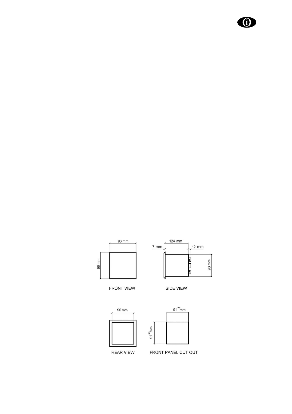
2.3 MOUNTING...................................................................................................................................2.1
2.4 WIRING.........................................................................................................................................2.2
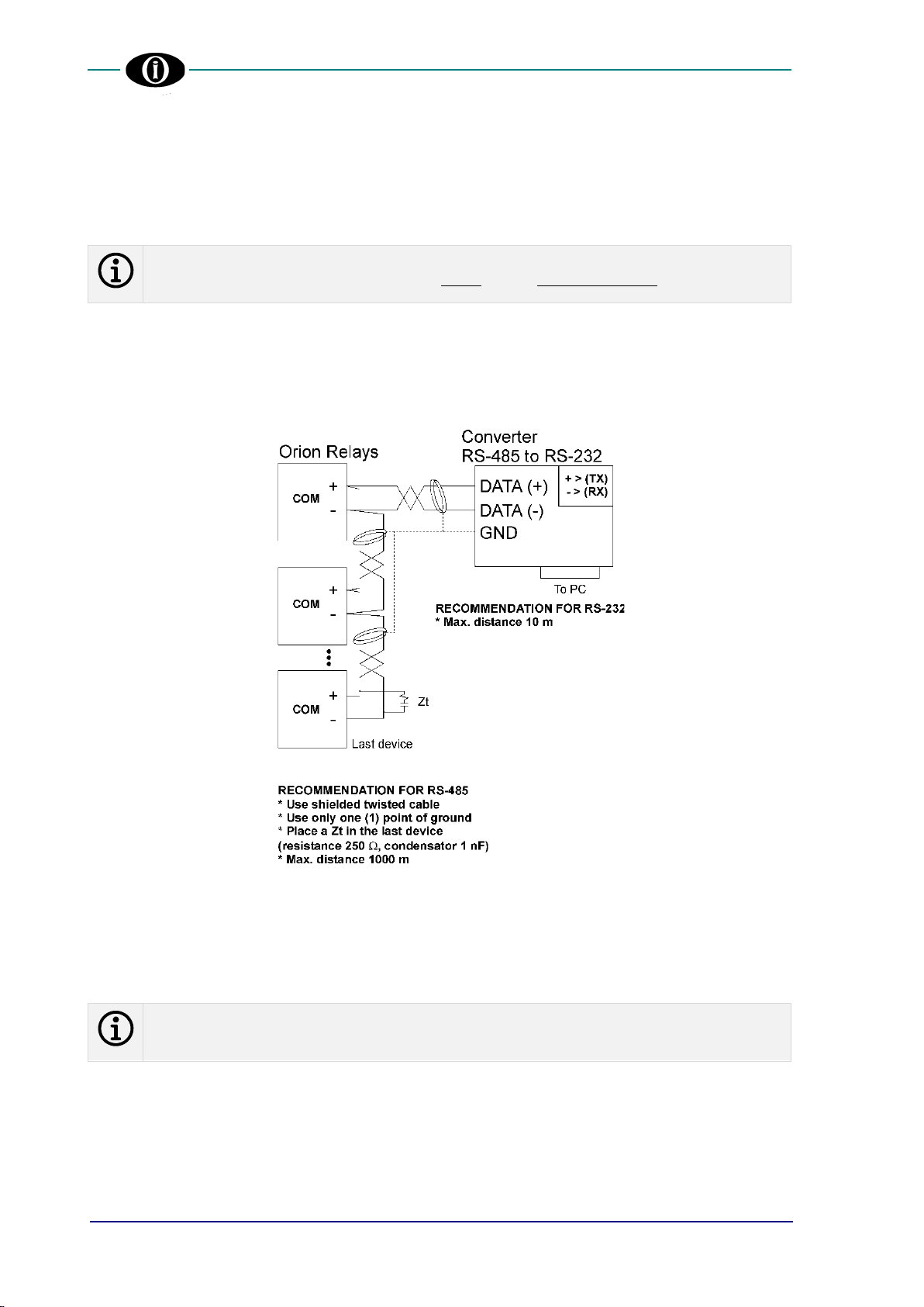
2.5 COMMUNICATIONS.....................................................................................................................2.4
2.6 POWER SUPPLY..........................................................................................................................2.4
3. Main Menu, Autoscroll and Pop-Up Functions .......................................................................................3.1
3.1 MENU STRUCTURE.....................................................................................................................3.1
3.2 AUTOSCROLL FUNCTION...........................................................................................................3.1
3.3 POP-UP FUNCTION.....................................................................................................................3.1
3.4 MENU SURFING...........................................................................................................................3.1
3.5 PASSWORD MANAGEMENT.......................................................................................................3.2
3.6 EDITING AND STORING KEYS ...................................................................................................3.2
3.7 FUNCTION KEY............................................................................................................................3.3
3.8 SYMBOLS USED IN THE TEXT...................................................................................................3.3
4. Menu RELAY STATUS...............................................................................................................................4.1
4.1 RELAY STATUS ...........................................................................................................................4.1
5. Menu ACTUAL VALUES............................................................................................................................5.1
5.1 Actual values: GROUND CURRENT.............................................................................................5.1
5.2 Actual values: LAST TRIP DATA ..................................................................................................5.1
5.3 Actual values: MAINTENANCE DATA ..........................................................................................5.1
6. Menu SETPOINTS......................................................................................................................................6.1
6.1 Setpoints: SETPOINT ACCESS....................................................................................................6.1
6.2 Setpoints: SYSTEM SETUP..........................................................................................................6.1
6.3 Setpoints: DATE & TIME...............................................................................................................6.2
6.4 Setpoints: GROUND PROTECTION.............................................................................................6.3
6.5 Setpoints: DIGITAL INPUT............................................................................................................6.4
6.6 Setpoints: OUTPUT RELAY..........................................................................................................6.5
6.7 Setpoints: EVENT RECORDER....................................................................................................6.6
6.8 Setpoints: MODBUS COMMUNICATION......................................................................................6.6
6.9 Setpoints: BLUETOOTH................................................................................................................6.7
6.10 Setpoints: FIRMWARE UPDATE ..................................................................................................6.7
6.11 Setpoints: CALIBRATION MODE..................................................................................................6.7
7. Menu EVENTS............................................................................................................................................7.1
7.1 EVENT LIST..................................................................................................................................7.1
7.2 CLEAR EVENTS...........................................................................................................................7.1
8. Menu RESET ..............................................................................................................................................8.1
8.1 RESET ..........................................................................................................................................8.1
9. Troubleshooting ........................................................................................................................................9.1
APPENDIX A
APPENDIX B
APPENDIX C

1. General Information
IPR96D Ground Protection Relay 1.1 Instruction Manual: IPR96D GBM 24/11/2020
1. General Information
1.1 DESCRIPTION
Ground Protection Relay (IPR96D) has been designed to measure the ground RMS current under normal conditions or under
disturbances.
The current signals are sensed throughout a current transformer (CT). This information is internally processed by the
microprocessor in order to take the current protection actions defined under ANSI, IAC or IEC standard.
1.2 APPLICATIONS
•Primary and backup protection for utility feeder, power plants and industrial distribution systems
1.3 DIGITAL MEASUREMENT
•Ground RMS Currents
1.4 FEATURES
•CT rated primary selectable in 5 A steps (5 A to 5000 A)
•Ground RMS current measurement
•1 trip relay and 2 programmable auxiliary relay
•Control power drop or internal fault relay
•Breaker operation & trip failure
•Digital input functions:
oremote TRIP
oremote RESET
oremote Aux Relay activation
obreaker Status
1.5 COMMUNICATION
•Communication port RS485
•Remote programming of the setpoints
•Communication Protocol: Modbus RTU
1.6 SIGNALLING AND PROGRAMMING
•LED and LCD display indication
•Ground current indication
•Indication and storage through a Pop-Up function, of fault conditions and their values
•Available leds:
Led
Description
Duty Cycle
Status
(keep alive)
-It indicates that the device is switched on and the self-diagnosis has not encountered any
problems.
-When it blinks, it indicates an error in setpoint discrepancy, flash memory, RAM memory, ADC
or Bluetooth BLE.
OFF = 3s
ON = 0.1s
OFF = 0.3s
ON = 0.3s
Trip
-The protection function has activated the TRIP relay.
-A breaker failure has occurred. A protection has activated the TRIP relay, but the breaker did
not interrupt the circuit.
ON = fixed
OFF = 0.3s
ON = 0.3s
Reclose
*Optional. Available depending on model type.
In case of setpoint discrepancy, check [Troubleshooting].
1.7 PROTECTIONS AND FUNCTIONALITIES
•(50G/50N) Instantaneous ground overcurrent
•(51.1G/51.1N) Ground timed overcurrent
•(51.2G/51.2N) Ground timed overcurrent
•ANSI, IAC or IEC/BS142 curves included:
omoderately inverse
onormal inverse
overy inverse
oextremely inverse
odefinite time

1. General Information
IPR96D Ground Protection Relay 1.2 Instruction Manual: IPR96D GBM 24/11/2020
1.8 SPECIFICATIONS
SUPPLY VOLTAGE
Options: (See Section 1.9 Order Code)
Model A: 120/230 Vac, -15%, +10%, 50/60 Hz
Model W: 85V (115V) 264V (300V) Vac (Vdc)
Model B: 24Vdc -15%, +10%,
Model C: 48Vdc -15%, +10%
TEMPERATURE
Operational: 0°C +50°C
Storage temperature: -20°C +70 °C
ELECTRICAL INSULATION CONSTRUCTION
OverVoltage category: III
Pollution degree: 2
Altitude: 2000m (AMSL)
GROUND CT INPUT
CT Rated Primary Current (IPn) 5A to 5000A, Steps: 5
CT Rated Secondary Current (ISn) 1A and 5A
Sampling: True RMS, 32 sample/s
CT burden: 0.25 VA (5A input)
0.1 VA (1A input)
Continuous Current: 2xISn
Current withstand capac.: 30 times ISn for 1 sec.
Accuracy: at <= ISn → ±0.5% x ISn
at > ISn → ±0.5% of 20x ISn
INSTANTANEOUS GROUND OVERCURRENT
(50 N/G)
Pickup Level: 1% to 2000% of CT, Steps: 1% / 10%
Delay Time: 0 to 2000 ms, Steps: 10 ms
Accuracy Pickup: ±1% CT
Time +40 ms max
GROUND TIME OVERCURRENT (51.1 N/G)
Pickup Level: 1% to 300% of CT, Steps: 1%
Time Multiplier: 0.1 to 20.0 for each curve
Accuracy Pickup: ±1% CT
Time ±3% of trip time or 20 ms
Delay time: 0.5s →600s,
Steps: 0.1s (from 0.5s to 10s); 1s (from 10s to
600s)
GROUND TIME OVERCURRENT (51.2 N/G)
Pickup Level: 1% to 300% of CT, Steps: 1%
Time Multiplier: 0.1 to 20.0 for each curve
Accuracy Pickup: ±1% CT
Time ±3% of trip time or 20 ms
Delay time: 0.5s →600s,
Steps: 0.1s (from 0.5s to 10s); 1s (from 10s to
600s)
MAX. POWER CONSUMPTION
6 VA (4 W)
RELATIVE HUMIDITY
Max. 90% (non-condensing)
BURN IN
48 hours at 50 °C
DIELECTRIC WITHSTAND VOLTAGE
2 kVac, 60s from all circuits and enclosure
2 kVac, 60s between HLV and LV circuit
DIGITAL INPUT
(2) dry contacts
Max connection lengths: 3mt
Rated Voltage: 5 Vdc internally powered
OUTPUT CONTACT
(1) trip relay and (2) programmable auxiliary relays
Rated load: 8A@ 240Vac Resistive
8A@ 24Vdc Resistive (0,2 A @125 Vdc)
Max Switching Voltage: 250 Vac / 150 Vdc
Max Continuous Current: 5 A
MECHANICAL
Back connection, section 2,5 mm² or 14 AWG
Frame: Noryl auto-extinguish
IP40 Front (up to IP54 front, on request)
Dimension: 96 x 96 x 113 mm.
Front panel cutout: 92 x 92 mm
Weight: 500 gr.
COMMUNICATION
RS-485 serial port
Protocol: Modbus RTU-Slave
Insulation: 1,5 kVdc
Bluetooth: 4.2
STANDARDS
Low voltage directive: IEC 60255-27, IEC 60255-5
EMC directive: IEC 60255-26
FIRMWARE UPGRADE
via RS-485 Serial Port
OTA via Bluetooth (Future option)
*Depending on IPR96D version
The term CT is intended as the abbreviation of CT Rated
Current; meaning IPn for the primary CT or ISn for the
secondary CT.
1.9 ORDER CODE
IPR96D X Y
Where X stands for MODEL:
1: Standard version (Secondary CT 1A/5A)
X: Special version
Where Y stands for POWER SUPPLY:
A: 120/230 Vac
W: 85÷240 Vac/dc
B: 24 Vdc
C: 48 Vdc

2. Installation
IPR96D Ground Protection Relay 2.1 Instruction Manual: IPR96D GBM 24/11/2020
2. Installation
2.1 DESCRIPTION
The label of the relay details the following information:
ORION ITALIA
TEL: 0523 591161
FAX: 0523 593898
www.orionitalia.com
MADE IN ITALY
POWER SUPPLY
GROUND CURRENT INPUTS RATINGS
MODEL: IPR96D
SERIAL No.
2.2 UNPACKING
The shipping container includes:
-the IPR96D Relay
-this instruction manual
-the fixing elements
-the Test Report (if required)
Inspect the unit and inform ORION ITALIA of any damage.
If reshipment is required, the original container and packing should be used.
2.3 MOUNTING
The mounting should be carried out as follows:
1. Install the relay in a place where the humidity and temperature are those for which it has been designed [General Information:
1.8 SPECIFICATIONS] and away from high current conductors and sources of strong magnetic fields.
2. Put the relay on a panel so that the keypad is easily accessible, and the display is visible.
3. Make a cutout in the panelboard [Figure 2.1] and fix the relay by using the fixing elements provided.
Figure 2.1
Overall dimensions

2. Installation
IPR96D Ground Protection Relay 2.2 Instruction Manual: IPR96D GBM 24/11/2020
2.4 WIRING
The electrical connections are made by terminal blocks on the back side of the unit.
CONNECTIONS
TERMINALS No.
Power Supply
1-2-3
Relays:
AUX2
AUX1
TRIP
10-11-12
13-14
15-16
Digital Inputs:
Com
DI_1
DI_2
41
42
43
Current Inputs
In= 1A: 21-22
In= 5A: 27-28
RS485
communication port
90-91
Before carrying out the installation of the unit, it is necessary to read and understand the indications provided by the
Constructor. All the installation operations must be carried out by qualified personnel with adequate knowledge of the
functioning of the unit and of the content of this manual.
The control power, current/voltage input and output contacts must be connected according to the supply voltage connection
diagram included in the present manual. Ensure applied currents/voltages abide by the IPR96D ratings indicated on the relay
label.
Orion Italia suggests that the maximum length of the digital input connections must be under 3mt.
Further information: →1.8 Specifications
Figure 2.2

2. Installation
IPR96D Ground Protection Relay 2.3 Instruction Manual: IPR96D GBM 24/11/2020
21 22
23 24 25 26
32 33 34
1 2 3 10 11 12 13 14 15 16 90 91
A
B
C
ORION ITALIA
IPR96D1
RS-485
Master
+
-
+
+
+
0V
115V
230V
AUXILIARY
POWER
115/230 Vac
50/60Hz
CURRENT
INPUT
In=1A
AUX2 AUX1
+
+
+
+
+
THREE-PHASE SYSTEM
(B)
+
(A)
-
n.u
27 28
n.u.
CT
xx/1A CT
xx/1A
Zero Sequence
Connection Residual
Connection
+
+
+
+
+
+
+
+
CT
xx/5A CT
xx/5A
Zero Sequence
Connection Residual
Connection
CURRENT
INPUT
In=5A
TRIP
AUXILIARY POWER
85(115)-240(300) Vac(Vdc)
24Vdc, 48Vdc
n.u -
+
L N
31
DIGITAL
INPUTS
51 52 53 54 55 56
n.u.
41 42 43
RS485
Com
DI.1
DI.2
Note:
(*)Output Contacts:
Usesurgesuppressoronoutput
contactswhencontrol contactors
orinductiveloads
(o)DigitalInputs:
3mMaxwiringlenght
OUTPUTCONTACTS
(*)
(o)
n.u.
n.u.
n.u.
n.u.
n.u.
n.u.
n.u.
n.u.
n.u.
n.u.
n.u.
n.u.
Figure 2.3 –Wiring diagram

2. Installation
IPR96D Ground Protection Relay 2.4 Instruction Manual: IPR96D GBM 24/11/2020
2.5 COMMUNICATIONS
Thanks to the serial port the monitoring and control of the relay can be made by a SCADA system, a PC or PLC device.
The ports provided are:
1 two-wire RS-485 port
→
1 twisted pair which transmits and receives alternatively is used for the data
TX and RX
For the RS-485 port use shielded & twisted pair wire to minimize communication errors from noise.
A suitable type of wire is: BELDEN#9841, AWG 24 which is shielded and with a characteristic impedance of 120 .
Ground the shield only at one point [Figure 2.4]
For the RS-485 port a maximum of 35 relays can be daisy chained together in parallel mode on a communication channel for a
MAXIMUM DISTANCE OF 1000 METERS.
For larger systems, additional RS-485 channels must be added.
To increase the number of relays over 35 on single channel, consult the relay constructor.
2.6 POWER SUPPLY
Voltage ranges for the relay →[General Information: 1.8 SPECIFICATIONS]
Power supply connection terminals →[Installation: 2.3 WIRING]
The relay has no internal fuses, external protection should be applied.
Orion Italia advices the use of 1 A timed external fuse.
Figure 2.4 –Communications

3. Main Menu, Autoscroll and Pop-Up Functions
IPR96D Ground Protection Relay 3.1 Instruction Manual: IPR96D GBM 24/11/2020
3. Main Menu, Autoscroll and Pop-Up Functions
3.1 MENU STRUCTURE
You can have access to the Main Menu by turning on the unit. The display shows the following options:
RELAY STATUS
→
status of the relay
ACTUAL VALUES
→
display of metering values
SETPOINTS
→
set up the general system and functions
EVENTS
→
visualize the last events stored and possibly clear them all
RESET
→
reset the IPR96D
Below, you can find the representation of the complete structure consisting of the Relay Main Menu and sub-menus.
3.2 AUTOSCROLL FUNCTION
When the user turns on the IPR96D, the unit will cyclically show the following screens:
Ground Current, Relay Status, Last Trip Data.
The Autoscroll mode will also be activated five (5) minutes after complete inactivity.
To exit, press any key on the IPR96D to return to the Main Menu.
3.3 POP-UP FUNCTION
Whenever there is a fault condition, the IPR96D display will immediately show a POP-UP screen with the cause of the last
protection intervention and the corresponding time stamp. To exit, press ⤺ESC.
3.4 MENU SURFING
To surf the menus, use one of the following keys:
▲
UP
→
move through the previous options of each menu
▼
DOWN
→
move through the next options of each menu
↲
ENTER
→
access the selected option
⤺
ESC
→
go back to the previous menu
Main Menu
Relay Status
Actual Values
Events
Setpoints
▼▲
Ground Current
▼▲
Last Trip Data
▼▲
Setpoint Access
▼▲
System Setup
▼▲
Date & Time
▼▲
Ground Protect.
▼▲
Digital Input
▼▲
Output Relay
▼▲
Firmware Update
▼▲
Calibration Mode
▼▲
Reset
▼▲
Event Recorder
▼▲
Modbus Comm.
▼▲
Bluetooth
▼▲
Event List
▼▲
Clear Events
Maintenance Data

3. Main Menu, Autoscroll and Pop-Up Functions
IPR96D Ground Protection Relay 3.2 Instruction Manual: IPR96D GBM 24/11/2020
3.5 PASSWORD MANAGEMENT
The IPR96D has three levels of password-granted authorizations:
FIRST LEVEL
→
view Actual Values and modify Setpoints.
A First-Level password cannot navigate through some of the options in the Calibration Mode
menu [APPENDIX A].
How to Set or Modify a First-Level password
DEFAULT FIRST-LEVEL PASSWORD: 1111
Setpoint Access
ORION ITALIA
IPR96DX F.V. X.XX
To modify the First-Level password, press ENTER.
Setpoint Access
ORION ITALIA
IPR96DX F.V. X.XX
Enter Password
- - - -
Insert the current First-Level password and press ENTER.
To edit and store the password, see [Main Menu, Autoscroll and Pop-Up
Functions: 3.6 EDITING AND STORING KEYS].
Password correct >> Setpoint Enabled.
This screen does not appear if the user has previously entered the correct
password. It will no longer be requested until 5min have passed since the last
press of any of the buttons (i.e. when it returns to Autoscroll mode).
Setpoint Access
Press Enter to Modify
the Password
Otherwise press
or Esc
Press ENTER and insert a new First-Level password.
Insert new password >> New Password Stored.
By changing the First-Level password, the Second-Level password will automatically change.
SECOND LEVEL
→
access every option on the First Level, some options on the Calibration Mode [APPENDIX A].
This password is obtained by adding 1 (to the first digit), 2 (to the second digit), 3 (to the third
digit) and 4 (to the fourth digit) of the First-Level password.
No digit in the resulting password can equal zero (0). If the sum of the two digits is greater
than ten (10), only the unit will be considered. If the sum equals ten (10), the digit will become
one (1).
For example: PSW1 = 9896 (new user password)
PSW1 = 1111 (factory default)
THIRD LEVEL
→
in this case, the user must contact Orion Italia to obtain the code.
It allows access to every option on the Second Level and the ability to alter the IPR96D
calibration settings [APPENDIX A].
3.6 EDITING AND STORING KEYS
To edit and store data, use the following keys:
▲
UP
→
increase the value
▼
DOWN
→
decrease the value
↲
ENTER
→
highlight the option and press ENTER to modify.
Change the value, press ENTER to store
PSW1
9
8
9
6
DEFAULT
PSW1
1
1
1
1
+
1
2
3
4
+
1
2
3
4
=
10
10
12
10
=
2
3
4
5
PSW2
1
1
2
1
PSW2
2
3
4
5

3. Main Menu, Autoscroll and Pop-Up Functions
IPR96D Ground Protection Relay 3.3 Instruction Manual: IPR96D GBM 24/11/2020
For example:
How to Change Ground CT Rating
Scroll ▲ or ▼and highlight the desired option, as shown in the following representation.
On the Main Menu, the user must select [6.2 Setpoints: SYSTEM SETUP]
System Setup
Ground CT Primary
50 A
Command
RS485
To modify the Ground CT Primary value, press ENTER.
The IPR96D will ask the user to insert a password.
System Setup
Ground CT Primary
50 A
Enter Password
- - - -
Press ▲ or ▼ to select the first digit of the password, press ENTER.
Repeat for the second, third and fourth digit.
Password correct >> Setpoint Access Enabled
Password incorrect >> Setpoint Access Disabled
This screen does not appear if the user has previously inserted the correct
password.
See [Main Menu, Autoscroll and Pop-Up Functions: 3.5 PASSWORD
MANAGEMENT].
System Setup
Phase CT Rating
Value
50 A
Password correct >> when the value blinks, press ▲ or ▼ to modify.
Press ENTER to store the new setpoint >> Setpoint Stored.
3.7 FUNCTION KEY
F
→
On the Main Menu or in Autoscroll mode, press Fand access the two available QR Codes by scanning them
with a cell phone or tablet equipped with internet.
Technical Support QR Code ▲ or ▼ Product Info QR Code.
3.8 SYMBOLS USED IN THE TEXT
This figure on the left represents the relay display.
This screen only appears if the statement on the left is applied.
[Main Menu option: SECTION]
If x = x
Symbol
;
→
Select among the elements on the list
→
Select any value within the indicated parameters
For example:
RANGE: 2; 3; 6 →select 2, or 3, or 6.
RANGE: 2 6 →select 2, or 3, or 4, or 5, or 6.
FRONT PANEL


4. Menu RELAY STATUS
IPR96D Ground Protection Relay 4.1 Instruction Manual: IPR96D GBM 24/11/2020
4. Menu RELAY STATUS
4.1 RELAY STATUS
Relay Status
No Active Protection
This section provides information on the Relay Status.
For example, the display could indicate protection interventions, internal faults
and/or setpoint discrepancies.
In the presence of more than four (4) alerts, navigate the list with the help of ▲ or
▼.
Normal conditions >> No Active Protection
[APPENDIX B] for all possible status.


5. Menu ACTUAL VALUES
IPR96D Ground Protection Relay 5.1 Instruction Manual: IPR96D GBM 24/11/2020
5. Menu ACTUAL VALUES
5.1 Actual values: GROUND CURRENT
Ground Current
Ig= 0.00 A
RMS Ground Current measured by residual connection or Zero Sequence CT.
See Wiring Diagram [Figure 2.3].
5.2 Actual values: LAST TRIP DATA
Last Trip Data
No Trip Data
The variables of the latest trip will be immediately displayed on this screen,
specifically showing date, time and cause of the last trip.
5.3 Actual values: MAINTENANCE DATA
Maintenance Data
Trips Counter 33
Ground O/C Counter
30
Trips Counter: it indicates the number of trips caused by protection interventions.
Ground O/C Trip: it counts the times the circuit breaker or disconnector
controlled by IPR96D has tripped due to the intervention of ground overcurrent
protection.
▼
Counters
Opening Counter
31
Maintenance Data
Clear? No
Opening Counter: it counts the breaker or disconnector openings.
If it is necessary to reset theMaintenance Data, press ENTER, insert the Second-
Level password (PSW2), scroll ▲ ▼ and select YES.
This type of clearing requires at least the Second-Level password (PSW2).
Actual Values
Ground Current
Last Trip Data
Maintenance Data


6. Menu SETPOINTS
IPR96D Ground Protection Relay 6.1 Instruction Manual: IPR96D GBM 24/11/2020
6. Menu SETPOINTS
Before carrying out the programming of the unit, it is necessary to read and understand the indications provided by the Constructor.
All the programming must be carried out by qualified personnel with adequate knowledge of the operation of the unit and of the
content of this manual.
6.1 Setpoints: SETPOINT ACCESS
Setpoint Access
ORION ITALIA
IPR96DX F.V. X.XX
IPR96D model and the firmware version.
Press ENTER, insert and/or modify the First-Level password (PSW1).
See [Main Menu, Autoscroll and Pop-Up Functions: 3.5 PASSWORD
MANAGEMENT].
6.2 Setpoints: SYSTEM SETUP
This section indicates the parameters for system setup.
System Setup
System
Frequency
Value 50 Hz
RANGE: 50; 60 Hz
Enter the nominal power system frequency. This value will set the optimal digital
sampling rate.
System Setup
Ground CT Primary
Value 50 A
RANGE: 5 5000
STEPS: 5
Enter the primary current rating of the ground CT being used.
System Setup
Command
Value RS485
RANGE: RS485, LOCAL, RS485+BLE, BLE
Choose the enabled command source and with this, disable all commands sent
by any other available communication methods or options.
The local HMI always remains enabled.
System Setup
Out of Service Relay
Value None
RANGE: None, Aux2
Select AUX2 to perform the SERVICE function
Once the power is applied, the relay will make AUX2 react and the related contact
will be opened. In case of fault of the relay (STATUS led “On”) or of loss of power
supply, AUX2 will pass to safe state position and exchange its contacts.
If the fault disappears, the IPR96D will get back to normal operation; the Out of
Service relay will remain latched in safe state position (local HMI reset required).
See Wiring Diagram [Figure 2.3].
Setpoints
Setpoint Access
System Setup
Date & Time
Ground Protect.
Digital Input
Output Relay
Event Recorder
Modbus Comm.
Bluetooth
Firmware Update
Calibration Mode

6. Menu SETPOINTS
IPR96D Ground Protection Relay 6.2 Instruction Manual: IPR96D GBM 24/11/2020
System Setup
Max Switching Current
Value ENABLED
RANGE: ENABLED; DISABLED
Indicate whether you want to enable or disable a current limit beyond which the
relay must not activate the TRIP output to avoid damaging the switching device
(useful when there is a switch/disconnector instead of a Circuit Breaker). In case
of Circuit Breaker, make sure to select DISABLED.
System Setup
Max Switching Current
Value 400 A
RANGE: 50 5000
STEPS: 10
The selected value indicates the current limit described in the screen above.
[6.2 Setpoints: SYSTEM SETUP]
If Max Switching Current = ENABLED
System Setup
Breaker Failure Relay
Value - - -
It allows selecting the output signaling the discrepancy between the trip command
sent by the protection relay and the signal received at the BREAKER STATUS
input from the circuit breaker or disconnector auxiliary contact.
This error information signals that the trip command has not provoked the opening
or that the auxiliary contact (52a) does not operate properly.
Disable this function in case of no connection between 52a auxiliary contact and
BREAKER STATUS input.
To disable the function, select "- - - ".
System Setup
Breaker Failure Delay
Value 1000 ms
RANGE: 10 2500
STEPS: 10
Delay for the circuit breaker auxiliary contacts to signal the opening. If a correct
reply is not obtained in this delay, an event for circuit breaker failure will be
displayed and the selected contact will activate.
[6.2 Setpoints: SYSTEM SETUP]
If Breaker Failure Relay ≠- - -
System Setup
Mech. Operations
Relay
Value - - -
Select the relays to be activated when reaching the max. number of mechanical
operations set in the next Line.
System Setup
Mech. Operations
Max
Value 3000
RANGE: 5 9995
STEPS: 5
This value represents the granted quantity of mechanical operations carried out
by the circuit breaker and the event indicates that maintenance is required.
[6.2 Setpoints: SYSTEM SETUP]
If Mech. Operations Relay ≠- - -
6.3 Setpoints: DATE & TIME
Date & Time
2018. Jan. 9 16:54:02:00
Press ENTER to modify.
Following the intervention of the Breaker Failure function, once the circuit breaker has been repaired, it will be necessary to
reset the IPR96D (if still in Tripped state) before proceeding to close the circuit breaker.
Table of contents
Other ORION ITALIA Relay manuals