ORION ITALIA TR42 User manual

TR-42 Temperature Protection Relay
1
Instruction Manual: TR42 GBM 25/02/2021
1. DESCRIPTION
The digital temperature relay TR-42 has been created as an accessory of main importance for resin or air insulated three-phase MT transformers, as
protection against dangerous over temperatures on the insulating coil, on the winding and to manage the intervention of cooling fans. The temperature is
detected by 3 or 4 thermal detectors PT 100, three of them located in the transformer coils, the fourth on the core.
Features
-Display of the actual temperature of the 4 PT sensors.
-Display & storage of the highest temperature of each PT sensor.
-3 programmable output contacts from 0° to 220°C level 1, level 2 and FAN
control.
-Automatic and “Always ON” fan mode.
-Alarm of device failure or PT 100 disconnection or short circuit.
-Automatic fan start every week (bearing protections).
-Insulated RS-485 communication port.
-Insulated 4-20mA output (Optional: see ORDER CODE).
2. INSTALLATION
Install the equipment according to the characteristics of humidity and temperature that has been designed to work in. To avoid noise pickup and interference
the relay should be placed away from high current conductors or sources of strong magnetic fields. The device has been designed for the installation on a
panel board with a cutout of 92x92mm using the fixing accessories that come with the relay. Before proceeding with the installation that must be carried
out by a qualified technician, it is recommended to disconnect the power supply on the working area. Orion Italia urges that security procedures be followed
during this installation.
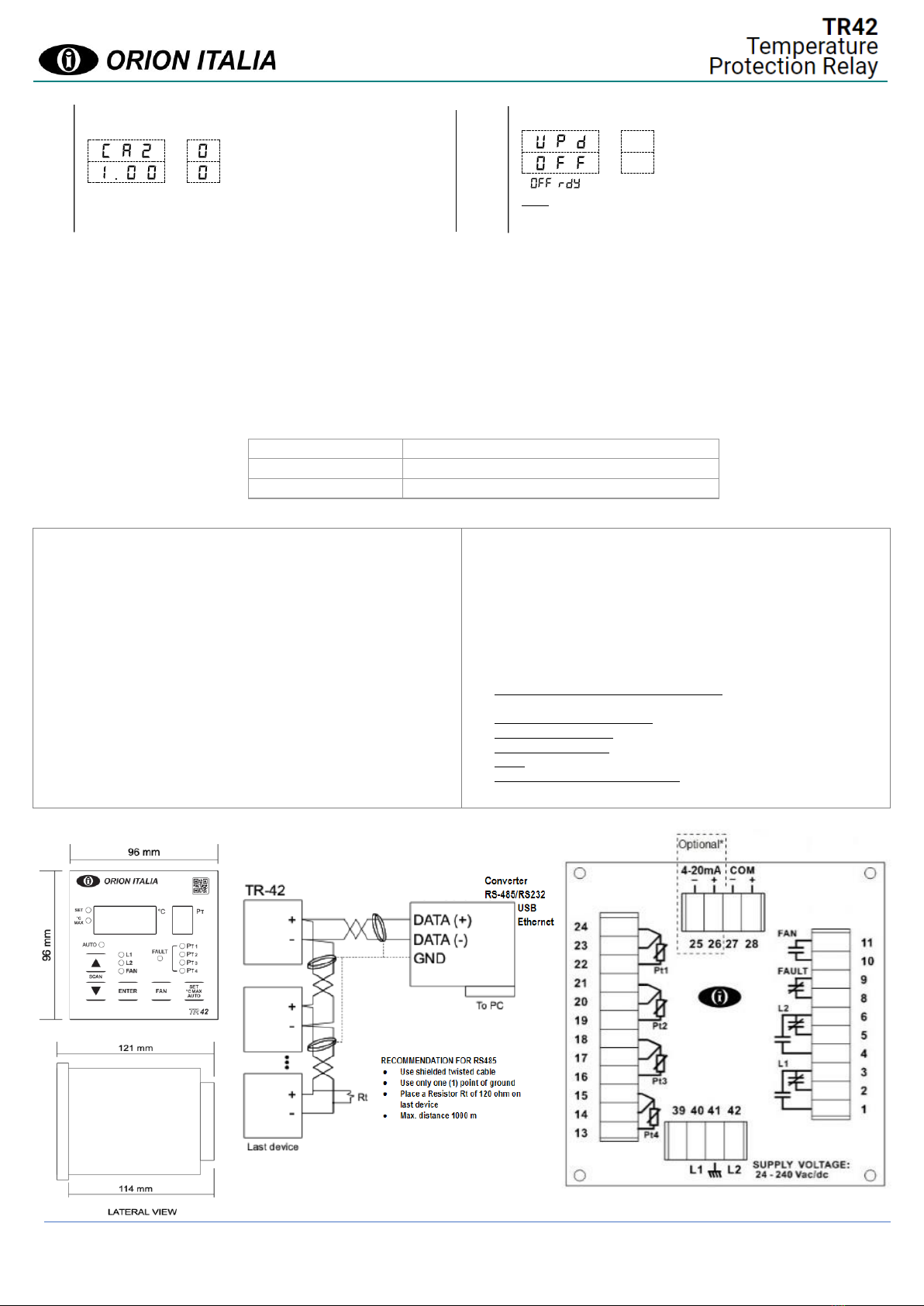
3. WIRING CONNECTION
For the connection, follow the diagram on page 4. Herein after the description of the different electric connections:
3.1 POWER SUPPLY
The power supply range is: 24-240 Vcc/Vca (50 –60Hz), -15%, +10% and power must be connected between the terminals 40 and 42. Note: The device does
not have internal fuses. This is to allow the selection of the desired external protection.
IMPORTANT: before doing the dielectric strength test of panel board, where the device is installed, it is necessary to disconnect it from the power line
voltage.
3.2 SENSORS CONNECTION
Each PT sensor has one white wire and two red ones according to the UNI 7937 regulation.
- Sensor cables should be made with shielded twisted pairs and the
shield should be connected to the system’s ground.
- To compensate the resistance of the wire, it is necessary to connect
each sensor with three (3) wires of the same section (at least 1 mm²).
- The probes wiring should be placed away from high current conductors,
high tension and from inductive elements such as remote-control switch,
etc. If the wires travel on the same route as the power lines, separate the
wires with suitable elements.
3.3 OUTPUT CONTACTS CONNECTION
In the back side of the device, it is possible to see the output contacts (in absence of power supply). The ALARM relay (L1), TRIP relay (L2) and fan control
(FAN) activate when temperature reaches the setpoint. The FAULT relay (FAULT) opens when power supply is connected and it will be closed when internal
failure occurs, failure of the PT sensors or failure of the power supply. The FAN contact can be used as a control of the cooling system. Note: When using
the contacts for control of inductive loads in Vac (coils of relays, contactors, solenoids), it is essential to limit the overcurrent, or place a R/C group in parallel
to the inductor. If it works in DC, a diode in anti-parallel should be connected.
3.4 SERIAL COMMUNICATION CONNECTION
Communication capabilities are available in the device connecting the RS-485 port in a network (up to 32 devices) controlled by a supervisor device (PC).
The protocol used is Modbus RTU. The connections must be made with shielded twisted wires.
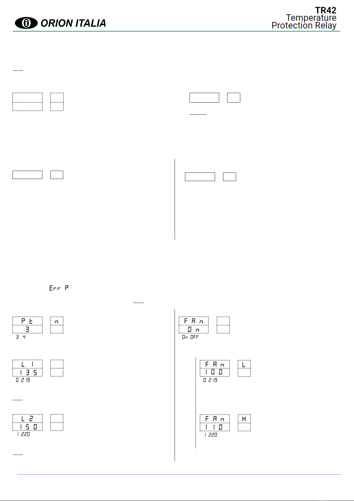
4. FUNCTIONS AND SIGNALS
Display: on the display °C (3 digits) you can observe the value of the temperature and program the settings; through the display PT (1 digit) you can see the
corresponding Pt Channel.
SET LED: if on, it indicates that the user is in the SET mode.
°C MAX LED: if on, it indicates that the user is in the °C MAX mode.
L1, L2 LED: if on, the temperature of one PT sensor reached the corresponding L1 or L2 programmed threshold and the corresponding relay is active.
FAN LED: if on, the “always ON” mode is active and the FAN relay will always be active. If flashing, the temperature of one PT sensor reached the
corresponding FAN programmed threshold or the weekly fan activation function is active and the FAN relay is active.
PT1, PT2, PT3, PT4 LEDs: if on, the temperature of one of the corresponding PT sensors reached the L1 or L2 programmed threshold and the corresponding
relay is active. If flashing, the respective PT sensor is in fault.
FAULT LED: if flashing, it indicates that the flashing PT1, PT2, PT3, PT4, is in fault. The fault cause will be showed through the °C display when positioned
with the arrow buttons on the faulty sensor: Fcc in case of short circuit and Fco for open circuit. Dropout condition for Fcc: T ≥ -7 °C. Dropout condition for
Fco: T ≤ 239 °C.
AUTO LED: if on, it means the user is in the AUTO SCAN mode.
HMI Test: depending on which menu the user is in, by pressing the SET, °C MAX, AUTO button and then keeping the DOWN button pressed, all LEDs and
seven segment LEDs will turn on.
SCAN, AUTO SCAN: in AUTO SCAN mode, the device will automatically scan between each PT sensor temperature showing it on the display every 5sec
allowing the user to see all the temperatures. To exit from the AUTO SCAN function, press any arrow button. The user will still be able to manually scan by
using the UP/DOWN buttons. By pressing the SET, °C MAX, AUTO button until the AUTO LED turns on, the AUTO SCAN function will reactivate. To activate
the AUTO SCAN function in °C MAX, select the °C MAX mode with the same button and keep the UP button pressed for more than 2sec.
FAN: the FAN button allows to switch between “always ON” or Automatic Fan Operation. In “always ON” mode, the fan will always be ON and the FAN LED
will be ON. In automatic mode, the fan will be ON and the FAN LED will blink when one PT sensor reaches the corresponding FAN programmed threshold.
If the setpoint FAN ACTIVATION = OFF, the manual fan will still allow the user to close/open the fan output contact.

TR-42 Temperature Protection Relay
2
Instruction Manual: TR42 GBM 25/02/2021
5. 4-20mA OUTPUT (Optional: see ORDER CODE)
An indicator can be connected to the 4-20mA output (polarity must be respected). The maximum load impedance is 500 Ω. The loop is isolated to ensure
maximum immunity from disturbances.
Ratio between output current and temperature: Iout = (T/15) + 4 [mA] where T = °C temperature
Note: It is recommended a shielded and twisted cable, avoiding bends or ring windings, placed away from power cables.
Symbols used in the text:
°C
PT
Blinking Displays
Two blinking displays alternate between the options on the first
row and the second row.
°C
PT
Fixed Displays
Example:
RANGE: 2; 3; 4 →select 2, or 3, or 4(select among the elements on the list).
RANGE: 2 ÷ 4 →select 2, or 3, or 4(select any value within the indicated
parameters).
6. ACTUAL VALUES
Each time the device is powered on, it turns on all LEDs and displays for about 2sec. Once this operation is over, the device begins to function automatically
in Current Temperature (AUTO) mode.
Current Temperature (AUTO)
X X X
Y
XXX: Temperature; Y:PT channel
Y: 1; 2; 3 if PT SENSORS CONNECTED = 3
Y: 1; 2; 3; 4 if PT SENSORS CONNECTED = 4
Press the SET, °C MAX, AUTO button until the °C MAX LED and the SET
LED are off.
The user will see the actual temperature on the °C display and the relative
PT sensor input on the PT display. To manually scroll through the PT
channels, press the UP/DOWN buttons. The SET and °C MAX LEDs are
off.
Maximum Temperature (oC MAX mode)
X X X
Y
XXX: Temperature; Y:PT channel
Y: 1; 2; 3 if PT SENSORS CONNECTED = 3
Y: 1; 2; 3; 4 if PT SENSORS CONNECTED = 4
Press the SET, °C MAX, AUTO button until the °C MAX LED is on. The user
will see the maximum temperature reached on the °C display and the
relative PT sensor input on the PT display. To manually scroll through the
PT channels, press the UP/DOWN buttons.
By pressing ENTER for 2sec, the last maximum temperature of the
visualized PT sensor is cleared and the next °C reading will be considered
the maximum. During this operation, the SET LED is off.
7. SETPOINTS
Press the SET, °C MAX, AUTO button until the SET LED is on.
PROGRAMMING MODE (SET mode)
By pressing SCAN (UP/DOWN buttons), the user can navigate the setpoints. Once on the menu option desired, the display will blink between the new value
and the value currently set.
STEP 1: keep the ENTER button pressed for at least 2sec.
STEP 2: insert the password (three digits) with UP/DOWN and ENTER buttons. If the password is correct, the value to be modified will blink. Otherwise, the
display will show for a few seconds.
STEP 3: use the direction buttons to set the new value.
STEP 4: press ENTER to confirm. Note: If the password is disabled or has been previously inserted, STEP 2 will be skipped.
PT SENSORS CONNECTED
;
Select the number of PT sensors connected.
ALARM RELAY (L1)
÷Step: 1
Set the value at which the L1 contact will operate.
The dropout (reset) value is 2°C less than the setpoint.
Note: L1 must be < L2.
TRIP RELAY (L2)
÷Step: 1
Set the value at which the L2 contact will close.
The dropout (reset) value is 2°C less than the setpoint.
Note: L2 must be > L1.
FAN ACTIVATION
;
If a fan is connected to the FAN contact, select ON.
FAN OFF LEVEL
÷Step: 1
FAN will be turned OFF at this temperature.
Based on the thermal inertia of the system, choose an appropriate
temperature delta between FAN L and FAN H.
FAN ON LEVEL
÷Step: 1
FAN will be turned ON at this temperature.
Visible only if FAN ACTIVATION = ON

TR-42 Temperature Protection Relay
3
Instruction Manual: TR42 GBM 25/02/2021
Visible only if FAN ACTIVATION = ON
PT SENSORS ENABLED FOR FAN
;
Select 4if the temperature of the PT4 sensor will be considered
for the control of the FAN contact. If 3is chosen, PT4 will NOT be
considered.
WEEKLY FAN
;
If ON, the FAN contact will be closed for 5min each week. This
function is useful in case the fans connected have not been used
for a long time, causing mechanical parts (bearings) to
deteriorate, increasing reliability.
BUZZER (Optional: see ORDER CODE)
; ;
A high-pitched tone will sound when temperature reaches the L1 or L2
threshold. This buzzer is installed inside the product.
COMMUNICATION BAUD RATE
9
6
(9600); (19200); (38400); (57600);
(115200)
Baud rate.
ADDRESS
1
÷
Modbus address.
PARITY
; ; ; ; ;
Parity and stop bit.
LOCAL/REMOTE CONTROL
;
:No setpoint modifications via RS-485, except oC MAX reset.
:Setpoint modifications via RS-485 are allowed.
4-20mA OUTPUT CHANNEL (Optional: see ORDER CODE)
;; ; ;;
Select how the temperatures will be transmitted through the
4-20mA output.
, , or : only the selected PT will be transmitted.
: this option will scan each PT sensor every 5sec.
: hottest PT sensor among the ones connected.
4-20mA OUTPUT LOAD (Optional: see ORDER CODE)
100;200;300;400;500
Select the resistive load [Ω].
PASSWORD MANAGEMENT
; ;(change password)
:password not requested to modify the setpoints.
: password requested to modify the setpoints.
:the user can change the password only if: password previously
inserted and USER LOGIN STATUS = ON.
STEP 1: the display will show (new password).
STEP 2: insert the three new digits.
To abort press the SET, °C MAX, AUTO button or wait 20sec without pressing
any key.
STEP 3: to confirm the new password inserted, press ENTER. The display
will show .
Forgot password? Reset to factory default password ( ).
STEP 1: disconnect all PT sensors.
STEP 2: keep simultaneously pressed the UP and DOWN buttons for 2sec.
The display will show . The password is now reset.
USER LOGIN STATUS
;
If the password was previously inserted, the user will remain
logged in for 5min from the last button pressed.
TEST
: ;;;;;
The ;;;(fault) relay tests work only if the
relays are not already excited. It lasts approximately
5sec.
The Test will simulate the following temperatures
for 5sec each: 60°C, 180°C, 60°C and 180°C.
(buzzer) Test.
4-20mA INDICATOR CALIBRATION ENABLING MENU
(Optional: see ORDER CODE)
;
Select ON to enable the 4mA and the 20mA indicator calibration correction.
CALIBRATION CORRECTION AT 4mA (Optional: see
ORDER CODE)
0.800÷1.200 Step: 0.001
4mA will be applied to the output and it will be possible to correct
the calibration value.
Visible only if
PSW MANAG. = ON
Visible only if
USER LOGIN STATUS = ON
Visible only if
4-20mA CALIBRATION
ENABLING MENU = ON

TR-42 Temperature Protection Relay
4
Instruction Manual: TR42 GBM 25/02/2021
CALIBRATION CORRECTION AT 20mA (Optional: see
ORDER CODE)
0.800÷1.200 Step: 0.001
20mA will be applied to the output and it will be possible to correct
the calibration value.
FIRMWARE UPGRADE
;
Note: for manufacturer’s use only.
8. MAINTENANCE
The device has been constructed principally with solid state technology, so it needs a simple maintenance. The operations of maintenance are simplified
as follows: keep the relay dry and clean, verify that all terminal blocks are well connected, periodically check the display test by which all LEDs will be on,
periodically control the right function of the output relays.
9. WARRANTY
The purchased product is covered by the manufacturer's or seller's warranty within the terms set out in the General Conditions of Sale, which can be
consulted on the website www.orionitalia.com and/or in the purchase contract stipulated. Orion Italia, S.r.l. warrants this product to be free from defects
in material and workmanship. To exercise this warranty, write or call your local Orion Italia representative, or contact Orion Italia in Piacenza, Italy. You will
be given prompt assistance.
10. ORDER CODE
Model
Description
TR42CM
Communication Port RS485
TR42AD
Communication Port RS485 + 4-20mA output + Buzzer
11. SPECIFICATIONS
Scale: -10 ÷ +240 °C
Accuracy: ±1% F.S. ± 1 digit
Settings: L1, L2, FAN: 0 ÷ 220 °C
Supply voltage: 24-240 Vcc/Vca (50-60Hz), -15%, +10%
Maximum power consumption: 4VA or 4W
Inputs: 4 platinum sensors PT100 with 3 wires. 500 Ohm max wire impedance.
Outputs: FAN: normally open, Imax 16A 240Vac/24Vdc resistive load (7A
continuous) /1HP 240 Vac. L1,L2: change-over 5A(n.o) res. load 250 Vac.
FAULT: 5A(n.c)
Operational Temperature: 0 ÷ 50 °C
Storage Temperature: –20 ÷ 70 °C
Relative Humidity: 90% (non-condensing)
Burn in: 48 hours
Dielectric Withstand Voltage: 2 kVac, 60s
Construction: according to the VDE, UL, CEI standards.
Terminal block: draw-out terminals for 4 mm² cables (12 AWG).
Frame: In ABS self-extinguish with frontal protection (IP54).
Assembly: to be fixed in the structure through stirrups and screws.
Dimensions: 96x96x114 mm Cutout: 91-0,5x 91-0,5 mm (±0,5 mm)
Weight: 500 grams
Communication port: Insulated RS-485, insulation 1500 Vdc.
Communication protocol: MODBUS RTU, function: 03h, 04h, 05h, 06h, 10h.
4-20 mA output: Internal power supply 15 Vdc, max. Voltage drop 10 V,
insulation voltage 1500 Vdc. Range: 0 °C÷240 °C. Accuracy: ±1% F.S. No
external power supply needed.
Emissions Tests:
Radiated emissions: EN 55011; Port: enclosure.
Conducted emissions: EN 55011; Port: AC mains.
Immunity Tests:
•Conducted disturbances induced by RF field: EN 61000-4-6; Port: AC mains
and signal lines.
•Radiated electromagnetic field: EN 61000-4-3; Port: enclosure.
•Electrostatic discharge: EN 61000-4-2; Port: enclosure.
•Fast transients (burst): EN 61000-4-4; Port: AC mains and signal lines.
•Surge: EN 61000-4-5; Port: AC mains.
•Voltage dips and short interruptions: EN 61000-4-11; Port: AC mains.
DIMENSIONS COMMUNICATION WIRING
Visible only if
4-20mA CALIBRATION
ENABLING MENU = ON
Visible only if
USER LOGIN STATUS
= ON
This manual suits for next models
2
Other ORION ITALIA Relay manuals