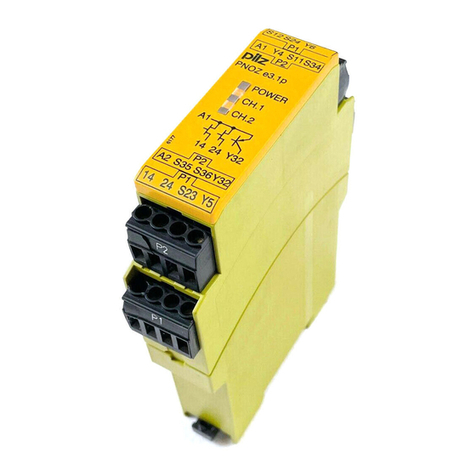
Pilz PNOZ mmc7p CC User manual

PNOZmmc7pCC
OperatingManual1003066EN02
ConfigurableControlSystemPNOZmulti

Preface
Thisdocumentistheoriginaldocument.
AllrightstothisdocumentationarereservedbyPilzGmbH&Co.KG.Copiesmaybemade
forinternalpurposes.Suggestionsandcommentsforimprovingthisdocumentationwillbe
gratefullyreceived.
Pilz®,PIT®,PMI®,PNOZ®,Primo®,PSEN®,PSS®,PVIS®,SafetyBUSp®,
SafetyEYE®,SafetyNETp®,thespiritofsafety®areregisteredandprotectedtrademarks
ofPilzGmbH&Co.KGinsomecountries.
SDmeansSecureDigital

Content
OperatingManualPNOZmmc7pCC
1003066EN02 3
Section1 Introduction 4
1.1 Validityofdocumentation 4
1.2 Usingthedocumentation 4
1.3 Definitionofsymbols 4
Section2 Overview 6
2.1 Scopeofsupply 6
2.2 Unitfeatures 6
2.3 Frontview 7
Section3 Safety 8
3.1 Intendeduse 8
3.2 Systemrequirements 8
3.3 Safetyregulations 9
3.3.1 Useofqualifiedpersonnel 9
3.3.2 Warrantyandliability 9
3.3.3 Disposal 9
3.3.4 Foryoursafety 9
Section4 Functiondescription 10
4.1 Operation 10
4.2 Inputandoutputdata 10
4.3 Blockdiagram 11
Section5 Installation 12
5.1 Generalinstallationguidelines 12
5.2 Connectthebaseunitandexpansionmodules 12
5.3 Dimensions 12
Section6 Commissioning 13
6.1 Generalwiringguidelines 13
6.2 Connectingthesupplyvoltage 13
6.3 Interfaceassignment 13
6.4 DownloadmodifiedprojecttothePNOZmultisafetysystem 14
6.5 Connectionexample 14
Section7 Operation 15
7.1 Messages 15
Section8 TechnicalDetails 16
Section9 Orderreference 18
9.1 Product 18
9.2 Accessories 18

Introduction
OperatingManualPNOZmmc7pCC
1003066EN02 4
1 Introduction
1.1 Validityofdocumentation
ThisdocumentationisvalidfortheproductPNOZmmc7pCC.Itisvaliduntilnewdocu
mentationispublished.
Thisoperatingmanualexplainsthefunctionandoperation,describestheinstallationand
providesguidelinesonhowtoconnecttheproduct.
1.2 Usingthedocumentation
Thisdocumentisintendedforinstruction.Onlyinstallandcommissiontheproductifyou
havereadandunderstoodthisdocument.Thedocumentshouldberetainedforfutureref
erence.
1.3 Definitionofsymbols
Informationthatisparticularlyimportantisidentifiedasfollows:
DANGER!
Thiswarningmustbeheeded!Itwarnsofahazardoussituationthatposes
animmediatethreatofseriousinjuryanddeathandindicatespreventive
measuresthatcanbetaken.
WARNING!
Thiswarningmustbeheeded!Itwarnsofahazardoussituationthatcould
leadtoseriousinjuryanddeathandindicatespreventivemeasuresthatcan
betaken.
CAUTION!
Thisreferstoahazardthatcanleadtoalessseriousorminorinjuryplus
materialdamage,andalsoprovidesinformationonpreventivemeasures
thatcanbetaken.
NOTICE
Thisdescribesasituationinwhichtheproductordevicescouldbedam
agedandalsoprovidesinformationonpreventivemeasuresthatcanbe
taken.Italsohighlightsareaswithinthetextthatareofparticularimport
ance.

Introduction
OperatingManualPNOZmmc7pCC
1003066EN02 5
INFORMATION
Thisgivesadviceonapplicationsandprovidesinformationonspecialfea
tures.

Overview
OperatingManualPNOZmmc7pCC
1003066EN02 6
2 Overview
2.1 Scopeofsupply
2.2 Unitfeatures
UsingtheproductPNOZmmc7pCC:
Expansionmoduleforconnectiontoabaseunitfromtheconfigurablecontrolsystem
PNOZmultiMini.
Theproducthasthefollowingfeatures:
}CanbeconfiguredinthePNOZmultiConfigurator
}ConnectionforCCLink
}Stationaddressesfrom1...63,selectedviarotaryswitch
}Stationtype:RemoteDevice
}Occupiedstations:2
}24virtualinputsandoutputsonthecontrolsystemPNOZmulticanbedefinedinthe
PNOZmultiConfiguratorforcommunicationwiththefieldbusCCLink.Thenumberof
inputsandoutputscanbeextendedto128.Pleasenotethatwhentheextendedinputs
andoutputs24127areusedtheyhavedifferentproperties(seedocumententitled
"CommunicationInterfaces").
}Max.1PNOZmmc7pCCcanbeconnectedtothebaseunit
}Pluginconnectionterminals:
eitherspringloadedterminalorscrewterminalavailableasanaccessory(seeorder
reference)
}Pleaserefertothedocument"PNOZmultiSystemExpansion"forthePNOZmultibase
unitsthatcanbeconnected.

Overview
OperatingManualPNOZmmc7pCC
1003066EN02 7
2.3 Frontview
Legend:
}X1:CCLinkinterface
}0V,24V:Supplyconnections
}LEDs:
– Power
– Run
– LErr

Safety
OperatingManualPNOZmmc7pCC
1003066EN02 8
3 Safety
3.1 Intendeduse
ThefieldbusmodulePNOZmmc7pCCisanexpansionmoduleoftheconfigurablecontrol
systemPNOZmulti.Itisusedforcommunicationbetweentheconfigurablecontrolsystem
PNOZmultiandtheCCLink.
CCLinkisdesignedforfastdataexchangeatfieldlevel.TheexpansionmoduleCCLinkis
apassivesubscriber(Slave)inCCLink.ThebasiccommunicationfunctionswithCCLink
conformtoCCLinkV1.10.Thecentralcontroller(master)readsinputinformationfromthe
slavesandwritesoutputinformationtotheslavesaspartofeachcycle.Aswellasthecyc
licaltransferofusabledata,theexpansionmodulePNOZmmc7pCCalsohasdiagnostic
andcommissioningfunctions.DatatrafficismonitoredontheMaster/Slaveside.
Theexpansionmodulemayonlybeconnectedtoabaseunitfromtheconfigurablecontrol
systemPNOZmulti(pleaserefertothedocument"PNOZmultiSystemExpansion"forde
tailsofthebaseunitsthatcanbeconnected)
TheconfigurablecontrolsystemPNOZmultiisusedforthesafetyrelatedinterruptionof
safetycircuitsandisdesignedforusein:
}ESTOPequipment
}SafetycircuitsinaccordancewithVDE0113Part1andEN602041
Theexpansionmodulemaynotbeusedforsafetyrelatedfunctions.
Thefollowingisdeemedimproperuseinparticular:
}Anycomponent,technicalorelectricalmodificationtotheproduct
}Useoftheproductoutsidetheareasdescribedinthismanual
}Useoftheproductoutsidethetechnicaldetails(seechapterentitled"TechnicalDe
tails").
NOTICE
EMCcompliantelectricalinstallation
Theproductisdesignedforuseinanindustrialenvironment.Theproduct
maycauseinterferenceifinstalledinotherenvironments.Ifinstalledinother
environments,measuresshouldbetakentocomplywiththeapplicable
standardsanddirectivesfortherespectiveinstallationsitewithregardtoin
terference.
3.2 Systemrequirements
Pleaserefertothe"ProductModifications"documentinthe"Versionoverview"sectionfor
detailsofwhichversionsofthebaseunitandPNOZmultiConfiguratorcanbeusedforthis
product.

Safety
OperatingManualPNOZmmc7pCC
1003066EN02 9
3.3 Safetyregulations
3.3.1 Useofqualifiedpersonnel
Theproductsmayonlybeassembled,installed,programmed,commissioned,operated,
maintainedanddecommissionedbycompetentpersons.
Acompetentpersonissomeonewho,becauseoftheirtraining,experienceandcurrentpro
fessionalactivity,hasthespecialistknowledgerequiredtotest,assessandoperatethe
workequipment,devices,systems,plantandmachineryinaccordancewiththegeneral
standardsandguidelinesforsafetytechnology.
Itisthecompany’sresponsibilityonlytoemploypersonnelwho:
}Arefamiliarwiththebasicregulationsconcerninghealthandsafety/accidentpreven
tion
}Havereadandunderstoodtheinformationprovidedinthisdescriptionunder"Safety"
}Andhaveagoodknowledgeofthegenericandspecialiststandardsapplicabletothe
specificapplication.
3.3.2 Warrantyandliability
Allclaimstowarrantyandliabilitywillberenderedinvalidif
}Theproductwasusedcontrarytothepurposeforwhichitisintended
}Damagecanbeattributedtonothavingfollowedtheguidelinesinthemanual
}Operatingpersonnelarenotsuitablyqualified
}Anytypeofmodificationhasbeenmade(e.g.exchangingcomponentsonthePCB
boards,solderingworketc.).
3.3.3 Disposal
}Whendecommissioning,pleasecomplywithlocalregulationsregardingthedisposalof
electronicdevices(e.g.ElectricalandElectronicEquipmentAct).
3.3.4 Foryoursafety
Theunitmeetsallthenecessaryconditionsforsafeoperation.However,youshouldalways
ensurethatthefollowingsafetyrequirementsaremet:
}Thisoperatingmanualonlydescribesthebasicfunctionsoftheunit.Theexpanded
functionsaredescribedinthePNOZmultiConfigurator'sonlinehelp.Onlyusethese
functionsonceyouhavereadandunderstoodthedocumentations.
}Donotopenthehousingormakeanyunauthorisedmodifications.
}Pleasemakesureyoushutdownthesupplyvoltagewhenperformingmaintenance
work(e.g.exchangingcontactors).

Functiondescription
OperatingManualPNOZmmc7pCC
1003066EN02 10
4 Functiondescription
4.1 Operation
ThevirtualinputsandoutputsthataretobetransferredviathefieldbusCCLinkareselec
tedandconfiguredinthePNOZmultiConfigurator.Thebaseunitandthefieldbusmodule
PNOZmmc7pCCareconnectedviaajumper.Afterthesupplyvoltageisswitchedonor
thePNOZmulticontrolsystemisreset,thefieldbusmodulePNOZmmc7pCCisconfigured
andstartedautomatically.
LEDsindicatethestatusofthefieldbusmoduleCCLink.
TheconfigurationisdescribedindetailinthePNOZmultiConfigurator'sonlinehelp.
4.2 Inputandoutputdata
Thedataisstructuredasfollows:
}Inputarea
– InputsonPNOZmultiConfigurator:i00…i23
– InputdataCCLink:RYn,RY1nwithn=0…F
Example:i23>RY17
s FLBCBA9876543210
RY0n i15 i14 i13 i12 i11 i10 i09 i08 i07 i06 i05 i04 i03 i02 i01 i00
RY1n i23 i22 i21 i20 i19 i18 i17 i16
}Outputarea
– OutputsonPNOZmultiConfigurator:o00…o23
– OutputdataCCLink:RXn,RX1nwithn=0…F
Example:o22>Rx16
s FLBCBA9876543210
RX0n o15 o14 o13 o12 o11 o10 o09 o08 o07 o06 o05 o04 o03 o02 o01 o00
RX1n o23 o22 o21 o20 o19 o18 o17 o16
Detailedinformationondataexchangeisavailableinthedocument"CommunicationInter
faces"inthesectionentitled"Fieldbusmodules".
Thenumberofvirtualinputsandoutputscanbeextendedto128(seedocument"Commu
nicationInterfaces"inthesectionentitled"Fieldbusmodules")
INFORMATION
WhenpollingthetablesandsegmentsofthePNOZmulti,pleasenotethat
communicationontheCCLinkisviatheRegister.

Functiondescription
OperatingManualPNOZmmc7pCC
1003066EN02 11
4.3 Blockdiagram
24 V 0 V
24 V 0 V

Installation
OperatingManualPNOZmmc7pCC
1003066EN02 12
5 Installation
5.1 Generalinstallationguidelines
}TheunitshouldbeinstalledinacontrolcabinetwithaprotectiontypeofatleastIP54.
}Fitthesafetysystemtoahorizontalmountingrail.Theventingslotsmustfaceupwards
anddownwards.Othermountingpositionscoulddestroythesafetysystem.
}Usethenotchontherearoftheunittoattachittoamountingrail.
}Inenvironmentsexposedtoheavyvibration,theunitshouldbesecuredusingafixing
element(e.g.retainingbracketorendangle).
}Pushtheunitupwardsordownwardsbeforeliftingitfromthemountingrail.
}TocomplywithEMCrequirements,themountingrailmusthavealowimpedancecon
nectiontothecontrolcabinethousing.
}TheambienttemperatureofthePNOZmultiunitsinthecontrolcabinetmustnotexceed
thefigurestatedinthetechnicaldetails,otherwiseairconditioningwillberequired.
CAUTION!
Damageduetoelectrostaticdischarge!
Electrostaticdischargecandamagecomponents.Ensureagainstdischarge
beforetouchingtheproduct,e.g.bytouchinganearthed,conductivesur
faceorbywearinganearthedarmband.
5.2 Connectthebaseunitandexpansionmodules
Connectthebaseunitandtheexpansionmoduleasdescribedintheoperatinginstructions
forthebaseunits.
}Connecttheblack/yellowterminatortotheexpansionmodule.
}InstalltheexpansionmoduleinthepositioninwhichitisconfiguredinthePNOZmulti
Configurator.
5.3 Dimensions
115,0 (4,53“)

Commissioning
OperatingManualPNOZmmc7pCC
1003066EN02 13
6 Commissioning
6.1 Generalwiringguidelines
ThewiringisdefinedinthecircuitdiagramofthePNOZmultiConfigurator.
Pleasenote:
}Informationgiveninthe"Technicaldetails"mustbefollowed.
}Usecopperwiringwithatemperaturestabilityof75°C.
}Alwaysconnectthemountingrailtotheprotectiveearthviaanearthingterminal.This
willbeusedtodissipatehazardousvoltagesinthecaseofafault.
}Thepowersupplymustmeettheregulationsforextralowvoltageswithprotectivesep
aration.
CAUTION!
Onlyconnectanddisconnecttheexpansionmodulewhenthesupply
voltageisswitchedoff.
NOTICE
Wheninstalling,youmustrefertotheguidelinesoftheCANopenUser
Group.
6.2 Connectingthesupplyvoltage
Connectthesupplyvoltagetothefieldbusmodule:
}Terminal24V:+24VDC
}Terminal0V:0V
6.3 Interfaceassignment
ItispossibletodefinewhichoutputsonthesafetysystemwillcommunicatewithCCLink.
TheconnectiontoCCLinkismadeviaa5pinscrewconnector.
1 2 3 4 5
DA FG/
PE
DB DG SLD
DA
FG/PE
DB
DG
SLD
1:DA(ChannelA)
2:DB(ChannelB)
3:DG(Earth)

Commissioning
OperatingManualPNOZmmc7pCC
1003066EN02 14
4:SLD(Cableshield)
5:FG/PE(Functionalearth)
6.4 DownloadmodifiedprojecttothePNOZmultisafetysystem
Assoonasanadditionalexpansionmodulehasbeenconnectedtothesystem,theproject
mustbeamendedusingthePNOZmultiConfigurator.Proceedasdescribedintheoperat
inginstructionsforthebaseunit.
NOTICE
Forthecommissioningandaftereveryprogramchange,youmustcheck
whetherthesafetydevicesarefunctioningcorrectly.
6.5 Connectionexample
PNOZ mmc7p CC

Operation
OperatingManualPNOZmmc7pCC
1003066EN02 15
7 Operation
Whenthesupplyvoltageisswitchedon,thePNOZmultisafetysystemcopiestheconfigur
ationfromthechipcard.
TheLEDs“POWER”,“DIAG”,“FAULT”,“IFAULT”and“OFAULT”willlightuponthebase
unit.
TheexpansionmodulePNOZmmc7pCCisconfiguredandstartedautomatically.
7.1 Messages
Legend:
LEDon
LEDflashes
LEDoff
LED Meaning
Power green Supplyvoltageispresent
}Supplyvoltageisnotpresent
RUN Green Busconnectionavailable
}Busconnectionisnotavailable
}Status:timeout
}NosupplyvoltageatthefieldbusmodulePNOZmmc7pCC
LErr red Faultdetected:Wrongstationaddressortransmissionrate
red }Flashesevenly:settinghasbeenchangedduringoperationand
PNOZmmc7pCChasnotbeenrestarted
}Flashesunevenly:faultyconnection,e.g.terminatingresistoris
missing
}Busconnectionavailable
}NosupplyvoltageatthefieldbusmodulePNOZmmc7pCC

TechnicalDetails
OperatingManualPNOZmmc7pCC
1003066EN02 16
8 TechnicalDetails
General
Approvals CCC,CE,GOST
Electricaldata
Supplyvoltage
for Modulesupply
Voltage 24V
Kind DC
Voltagetolerance 20%/+25%
Outputofexternalpowersupply(DC) 1,5W
Statusindicator LED
Fieldbusinterface
Fieldbusinterface CCLinkV1.10
Unittype Slave
Stationaddress 1...63d
Transmissionrates 10MBit/s,156kbit/s,2,5MBit/s,5MBit/s,625kbit/
s
Connection 5pinCombiconpluginconnector
Assignedstations 2
Galvanicisolation Yes
Testvoltage 500VAC
Times
Supplyinterruptionbeforedeenergisation 20ms
Environmentaldata
Ambienttemperature
Inaccordancewiththestandard EN60068214
Temperaturerange 060°C
Forcedconvectionincontrolcabinetoff 55°C
Storagetemperature
Inaccordancewiththestandard EN6006821/2
Temperaturerange 2570°C
Climaticsuitability
Inaccordancewiththestandard EN60068230,EN60068278
Humidity 93%r.h.at40°C
Condensationduringoperation Notpermitted
EMC EN611312
Vibration
Inaccordancewiththestandard EN6006826
Frequency 10,0150,0Hz
Acceleration 1g
Shockstress
Inaccordancewiththestandard EN60068227
Acceleration 15g
Duration 11ms
Max.operatingheightabovesealevel 2000m

TechnicalDetails
OperatingManualPNOZmmc7pCC
1003066EN02 17
Environmentaldata
Airgapcreepage
Inaccordancewiththestandard EN611312
Overvoltagecategory II
Pollutiondegree 2
Ratedinsulationvoltage 30V
Protectiontype
Inaccordancewiththestandard EN60529
Mountingarea(e.g.controlcabinet) IP54
Housing IP20
Terminals IP20
Potentialisolation
Potentialisolationbetween Fieldbusandmodulevoltage
Typeofpotentialisolation Functionalinsulation
Ratedsurgevoltage 500V
Mechanicaldata
Mountingposition Horizontalontophatrail
DINrail
Tophatrail 35x7,5EN50022
Recesswidth 27mm
Material
Bottom PC
Front PC
Top PC
Conductorcrosssectionwithscrewterminals
1coreflexible 0,252,50mm²,2412AWG
2corewiththesamecrosssection,flexiblewith
crimpconnectors,noplasticsleeve 0,201,50mm²,2416AWG
2corewiththesamecrosssection,flexiblewithout
crimpconnectorsorwithTWINcrimpconnectors 0,201,50mm²,2416AWG
Rigidsinglecore,flexiblemulticoreormulticore
withcrimpconnector 0,51,5mm²
Torquesettingwithscrewterminals 0,50Nm
Connectiontype Springloadedterminal,screwterminal
Conductorcrosssectionwithspringloadedterminals:
Flexiblewith/withoutcrimpconnector 0,202,50mm²,2412AWG
Springloadedterminals:Terminalpointsperconnec
tion 2
Strippinglength 9mm
Dimensions
Height 100,0mm
Width 22,5mm
Depth 110,0mm
Weight 90g
Wherestandardsareundated,the201109latesteditionsshallapply.

Orderreference
OperatingManualPNOZmmc7pCC
1003066EN02 18
9 Orderreference
9.1 Product
Producttype Features Orderno.
PNOZmmc7pCC Fieldbusmodule,CCLink 772035
9.2 Accessories
Connectionterminals
Producttype Features Orderno.
Springterminals
PNOZmmcxp1pc.
Springloadedterminals,1pieces 783542
Springterminals
PNOZmmcxp10pcs.
Springloadedterminals,10pieces 783543
Screwterminals
PNOZmmcxp1pc.
Screwterminals,1piece 793542
Screwterminals
PNOZmmcxp10pcs.
Screwterminals,10pieces 793543
Terminator,jumper
Producttype Features Orderno.
PNOZmm0.xpconnector
left
Jumperyellow/blacktoconnectthemodules,1piece 779260

The Best of
German
En gineering
Partner of:
Support
Technical support is available from Pilz round the clock.
Americas
Brazil
+55 11 97569-2804
Canada
+1 888-315-PILZ (315-7459)
Mexico
+52 55 5572 1300
USA (toll-free)
+1 877-PILZUSA (745-9872)
Asia
China
+86 21 60880878-216
Japan
+81 45 471-2281
South Korea
+82 31 450 0680
Australia
+61 3 95446300
Europe
Austria
+43 1 7986263-0
Belgium, Luxembourg
+32 9 3217575
France
+33 3 88104000
Germany
+49 711 3409-444
Ireland
+353 21 4804983
Italy
+39 0362 1826711
Scandinavia
+45 74436332
Spain
+34 938497433
Switzerland
+41 62 88979-30
The Netherlands
+31 347 320477
Turkey
+90 216 5775552
United Kingdom
+44 1536 462203
You can reach our
international hotline on:
+49 711 3409-444
support@pilz.com
CMSE ®, InduraNET p ®, PAS4000 ®, PAScal ®, PASconfig ®, Pilz ®, PIT ®, PLID ®, PMCprimo ®, PMCprotego ®, PMCtendo ®, PMD ®, PMI ®, PNOZ ®, Primo ®, PSEN ®, PSS ®, PVIS ®, SafetyBUS p ®,
SafetyEYE ®, SafetyNET p ®, the spirit of safety ®are registered and protected trademarks of Pilz GmbH & Co. KG in some countries. We would point out that product features may vary
from the details stated in this document, depending on the status at the time of publication and the scope of the equipment. We accept no responsibility for the validity, accuracy
and entirety of the text and graphics presented in this information. Please contact our Technical Support if you have any questions.
Pilz develops environmentally-friendly products using
ecological materials and energy-saving technologies.
products and environmentally-friendly solutions.
Pilz GmbH & Co. KG
Felix-Wankel-Straße 2
73760 Ostfildern, Germany
Tel.: +49 711 3409-0
Fax: +49 711 3409-133
info@pilz.com
www.pilz.com
100XXXX-DE-0X
0-0-2-3-000, 2014-00 Printed in Germany
© Pilz GmbH & Co. KG, 2014
1003066EN02,201411PrintedinGermany
©PilzGmbH&Co.KG,2011
Backcover
Other manuals for PNOZ mmc7p CC
1
This manual suits for next models
1
Table of contents
Other Pilz Relay manuals

Pilz
Pilz PNOZ XV3.1P User manual

Pilz
Pilz P2HZ X1 User manual

Pilz
Pilz PNOZ s4.1 User manual

Pilz
Pilz PNOZ X1 User manual

Pilz
Pilz PNOZ X10.11P User manual

Pilz
Pilz PNOZ s6.1 User manual

Pilz
Pilz PNOZ 2VJ User manual

Pilz
Pilz PNOZ X2.1VP User manual

Pilz
Pilz PNOZ XV2 User manual

Pilz
Pilz PNOZ e3vp User manual