7SG12 DAD N Description of Operation
Contents
1INTRODUCTION................................................................................................................................................ 3
2HARDWARE DESCRIPTION............................................................................................................................. 3
2.1 General .................................................................................................................................................... 3
2.2 Analogue Inputs ....................................................................................................................................... 4
2.3 Status Inputs ............................................................................................................................................ 4
2.4 Output Relays .......................................................................................................................................... 4
2.5 Fascia LEDS ............................................................................................................................................ 5
2.6 Self Monitoring ......................................................................................................................................... 5
2.6.1 Protection Healthy/Defective ............................................................................................................ 5
3PROTECTION FUNCTIONS.............................................................................................................................. 5
3.1 Overall Differential (87/50-1, 87/50-2) ...................................................................................................... 5
3.2 CT Supervision (CT 50) ........................................................................................................................... 5
3.3 Trip Circuit Supervision ............................................................................................................................ 5
4OTHER FEATURES .......................................................................................................................................... 6
4.1 Metering ................................................................................................................................................... 6
4.2 Data Storage............................................................................................................................................ 6
4.2.1 General ............................................................................................................................................ 6
4.2.2 Waveform Records. ......................................................................................................................... 6
4.2.3 Event Records.................................................................................................................................. 6
4.2.4 Fault Recording................................................................................................................................6
4.3 Time Synchronisation............................................................................................................................... 7
4.3.1 IRIG-B Time Synchronisation........................................................................................................... 7
4.3.2 IEC 60870-5-103 Time Synchronisation........................................................................................... 7
4.3.3 Real Time Clock Time Synchronisation............................................................................................ 7
4.4 Communications ...................................................................................................................................... 7
4.5 Settings Groups ....................................................................................................................................... 7
4.6 Password Feature .................................................................................................................................... 7
5USER INTERFACE............................................................................................................................................ 8
5.1 Liquid Crystal Display............................................................................................................................... 8
5.2 Back light Control..................................................................................................................................... 8
5.3 LED Indications........................................................................................................................................ 8
5.4 Keypad..................................................................................................................................................... 8
5.5 Relay Identifier ......................................................................................................................................... 8
5.6 Settings Mode .......................................................................................................................................... 8
5.6.1 Settings Adjustment ......................................................................................................................... 8
5.6.2 Settings And Displays ...................................................................................................................... 9
5.7 Instruments Mode .................................................................................................................................. 10
5.7.1 Hidden Instruments ........................................................................................................................ 10
5.8 Fault Data Mode.................................................................................................................................... 10
5.9 Default Instruments Screens.................................................................................................................. 10
6DIAGRAMS...................................................................................................................................................... 12
Figures
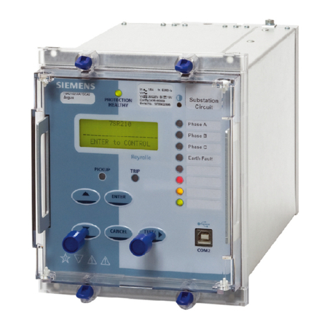
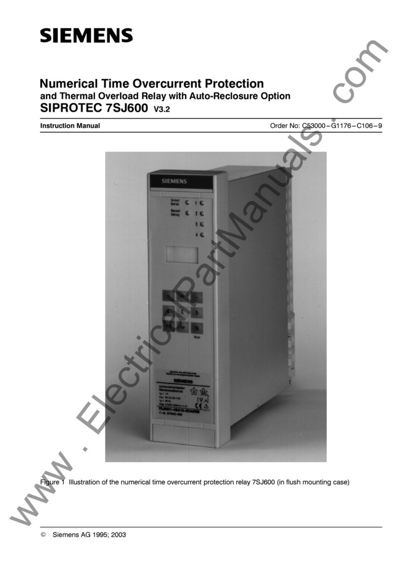
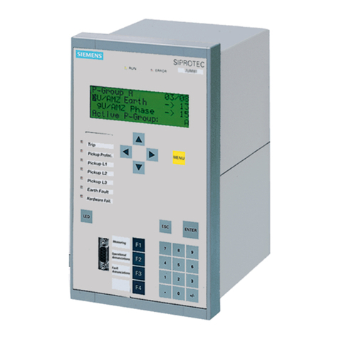
Figure 1 – DAD-N Numerical High Impedance protection........................................................................................ 3
Figure 2 – DAD-N in E8 case with front panel open............................................................................................... 12
Figure 3 – DAD-N Rear View ................................................................................................................................. 12
Figure 4 – High Impedance Differential Schematic ................................................................................................ 13
Figure 5 – DAD-N Menu Structure ......................................................................................................................... 14
©2010 Siemens Protection Devices Limited Chapter 1 Page 2 of 14
