Orion Atlas Pro AZ/EQ-G GoTo Mount User manual

Orion Atlas™Pro AZ/EQ-G
GoToMount
#10010
IN 479 Rev. B 06/17
INSTRUCTION MANUAL
Corporate Offices: 89 Hangar Way, Watsonville CA 95076 - USA
Toll Free USA & Canada: (800) 447-1001
International: +1(831) 763-7000
Copyright © 2021 Orion Telescopes & Binoculars.All Rights Reserved. No part of this product instruction or any of its contents
may be reproduced, copied, modied or adapted, without the prior written consent of Orion Telescopes & Binoculars.
AN EMPLOYEE-OWNED COMPANY
Español
Francais
Deutsche
Italiano
➊ Pour obtenir le manuel d'utilisation complet,
veuillez vous rendre sur le site Web OrionTele-
scopes.eu/fr et saisir la référence du produit dans
la barre de recherche.
➋ Cliquez ensuite sur le lien du manuel
d’utilisation du produit sur la page de description
du produit.
➊ Wenn Sie das vollständige Handbuch einsehen
möchten, wechseln Sie zu OrionTelescopes.de,
und geben Sie in der Suchleiste die Artikelnum-
mer der Orion-Kamera ein.
➋ Klicken Sie anschließend auf der Seite mit
den Produktdetails auf den Link des entsprech-
enden Produkthandbuches.
➊ Para ver el manual completo, visite
OrionTelescopes.eu y escriba el número de
artículo del producto en la barra de búsqueda.
➋ A continuación, haga clic en el enlace al
manual del producto de la página de detalle del
producto.
➊Per accedere al manuale completo, visitare
il sito Web OrionTelescopes.eu. Immettere the
product item number nella barra di ricerca
➋Fare quindi clic sul collegamento al manuale
del prodotto nella pagina delle informazioni sul
prodotto.

2
Congratulations on your purchase of
the Orion Atlas Pro AZ/EQ-G GoTo
Mount. Designed for use in either alt-
azimuth or equatorial modes, this ver-
satile, precision GoTo mount provides
a stable, high-performance platform for
astronomical observing or astrophotog-
raphy. These instructions will help you
set up and properly use your new mount.
Please read them over thoroughly before
getting started.
1. Unpacking
The entire mount will arrive in two boxes,
one containing the tripod and counter-
weights, the other containing the mount
head and hand controller. Be careful
unpacking the boxes. We recommend
keeping the boxes and original packag-
ing. In the event that the mount needs
to be shipped to another location, or
returned to Orion for warranty repair,
having the proper packaging will ensure
that your mount will survive the journey
intact.
Make sure all the parts in Figure 2 are
present. Be sure to check the boxes
thoroughly, as some parts are small. If
anything appears to be missing or dam-
aged, immediately call Orion Customer
Support (800-676-1343) or email sup-
port@telescope.com for assistance.
Figure 1. The Atlas Pro AZ/EQ-G mount
WARNING:
• Never look directly at the Sun with
the naked eye or with a telescope
– unless you have a proper solar
lter installed over the front of the
telescope! Otherwise, permanent,
irreversible eye damage may result.
• Never use your telescope to project
an image of the Sun onto any
surface. Internal heat build-up can
damage the telescope and any
accessories attached toit.
• Never use an eyepiece solar lter
or a Herschel wedge. Internal heat
build-up inside the telescope can
cause these devices to crack or
break, allowing unltered sunlight
to pass through to the eye.
• Never leave the telescope
unsupervised, either when
children are present or adults
who may not be familiar with the
correct operating procedures of
yourtelescope.

3
Table of Contents
1. Unpacking 2
2. Setting Up the Atlas Pro AZ/EQ-G Mount 4
2.1 Setting Up the Tripod and Mount Head 4
2.2 Attaching the Accessory Tray/Spreader
and the Hand Controller Holder 4
2.3 Attaching the Counterweights 5
2.4 Installing a Telescope on the Mount 6
2.5 Balancing the Telescope 7
3. Using the Atlas Pro AZ ⁄ EQ-G Mount 7
3.1 Manually Rotating the Mount 7
3.2 Using the Setting Circles 7
3.3 Adjusting the R.A. Axis Elevation (Latitude) 8
3.4 Setting the Mount to Alt-azimuth Mode 8
3.5 Mounting a Second Telescope (Alt-azimuth mode
only) 10
4. Polar Alignment 11
4.1 What Is It? 11
4.2 The Polar Axis Finder Scope 11
4.3 Aligning the Polar Axis Scope to the R.A. Axis 12
4.4 Polar Alignment Using the Polar Scope 12
4.5 Another Way to Determine Position of Polaris on
Reticle 13
5. Drive Panel Interface 14
5.1 Drive Panel 14
5.2 Panel Interface Components: 14
5.3 Pinout of the Interfaces 14
5.4 Attaching the SynScan GoTo Hand Controller 14
5.5 Power Supply Requirements 14
6. Other Atlas Pro AZ/EQ-G Features 15
6.1 Auxiliary Encoder Function 15
6.2 Permanent Periodic Error Correction 15
6.3 Batch Exposure Function 15
Specications 16
Figure 2. Components included with the Atlas Pro
Camera
control cable
PC interface
(serial) cable
Secondary
saddle
SynScan
hand controller
Counterweight
shaft extension
Hand controller
cable
Set of Allen
wrenches
Cable guide
DC power cable
Accessory
tray
Washer
Tripod
AZ/EQ
mount head
Counter-
weights
Knob
Hand
controller
bracket

4
2. Setting Up the Atlas Pro
AZ/EQ-G Mount
2.1 Setting Up the Tripod and Mount Head
1. Stand the tripod upright and spread the legs out as far
as they will go. Make certain that the leg lock levers are
tightened. Keep the tripod legs at their shortest (fully
retracted) length, for now; you can extend them to a more
desirable length later, after the mount is fully assembled.
2. Loosen the two azimuth adjustment knobs on the mount
head until there is ½" or more of space between the two
azimuth adjustment bolts (Figure 3a). Then place the
mount on the tripod, aligning the metal post on the tripod
with the gap between the two azimuth adjustment knobs
(Figure 3b).
3. Once the mount is seated, slightly tighten the two
azimuth adjustment knobs.
4. Thread the center support shaft up through the tripod top
and into the bottom of the mount head until tight. Use the
upper knob on the center support shaft to do this. The
mount head should now be rmly connected to the tripod.
2.2 Attaching the Accessory Tray/Spreader
and the Hand Controller Holder
1. Remove the knob and washer from the bottom of the
center support shaft. Slide the tripod support tray up the
bottom of the shaft until the three tray arms are touching
the legs of the tripod. The at side of the support tray
should be facing up. Make sure the “V” of each tray arm
is against a tripod leg. Place the washer on the center
support shaft against the tray, and follow it by threading
the knob all the way up the center support shaft until it is
tight against the tray (Figure 4). The tripod support tray
provides additional stability for the tripod, and holds up to
ve 1.25" eyepieces and two 2" eyepieces.
2. Using the bubble level on the mount (Figure 5), level
the mount by adjusting the length of the tripod legs as
needed.
3. Insert the hand controller holder into the U-shaped slot
on the accessory tray/spreader (Figure 6).
Warning:The accessory tray/spreader will ensure the
tripod legs remain rmly expanded, which will prevent
the tripod from accidentally toppling over. When using
the Atlas Pro mount, it is important to always install
the accessory tray/spreader before attaching the
telescope.
Figure 3. a) Loosen the azimuth adjustment bolts to create at least
a ½" gap. b) Orient the mount head so that the gap aligns with the
metal post on the tripod.
Azimuth
adjustment
knobs
Gap
Upper knob
on center
support
shaft
Figure 3a
a.
b.

5
2.3 Attaching the Counterweights
Always attach the counterweight(s) before installing your tele-
scope on the mount!
1. Loosen the T-bolt for locking the counterweight shaft
(Figure 7a) and fully extend the shaft. Re-tighten the
T-bolt to secure the shaft in place (Figure 7b).
Figure 4. Installing the tripod leg spreader, which doubles as an
eyepiece/accessory tray.
Figure 5. The bubble level at the base of the mount head makes
leveling the mount easy.
Upper
knob
Washer
Knob
Center
support
shaft
T-bolt
Safety
stop
Bubble
level
Figure 6. Hand controller bracket snaps into the slot in the
accessory tray.
Figure 7. a) Counterweight shaft retracted. b)Counterweight shaft
extended.
Slot Accessory
tray/spreader
Hand
controller
bracket
a.
b.

6
2. Loosen the right ascension (R.A.) clutch with the
handle (Figure 8a), and rotate the R.A. axis until the
counterweight shaft is pointing toward the ground, as in
Figure 7b.
3. Remove the knurled “toe saver” safety stop (Figure 7b)
from the end of the counterweight shaft.
4. The Atlas Pro mount comes with a 150mm counterweight
shaft extension (Figure 9), which can be installed at this
point if necessary for balancing heavier payloads. Ensure
that the extension is tightly secured before installing
counterweights.
5. Loosen the counterweight’s lock knob and slide one or
more counterweights onto the counterweight shaft as
needed to balance your instrument. (See Section 2.5 for
details on how to balance the telescope.) Retighten the
lock knob to secure the counterweight on the shaft.
6. Replace the safety stop on the end of the counterweight
shaft. The safety stop prevents the counterweights from
falling on your foot if the lock knobs come loose.
2.4 Installing a Telescope on the Mount
The Atlas Pro mount is designed to hold a telescope payload
of up to 44 lbs. For heavier telescopes, the mount may not
provide sufficient stability for steady imaging.
1. Before installing a telescope, be sure that:
• The counterweight shaft is pointing toward the ground.
• The counterweights are installed on the counterweight
shaft and have been moved to the bottom end of the
shaft.
• The R.A. axis is secured by tightening the R.A. clutch.
2. Loosen the two clamp knobs on the primary dual-width
saddle plate (Figure 10) until the width of one of the
Figure 8. a) Right ascension clutch. The handle can be placed in
an adjacent hole if needed. b) Declination clutch.
Figure 10. The primary dual-width saddle accommodates narrow
or wide dovetail plates.
Figure 9. The included 150mm counterweight shaft threads into the
bottom of the main shaft.
R.A. clutch
handle
Dec clutch
“captain’s wheel”
75mm, wide
45mm,
narrow
Clamp
knobs
T
I
G
H
T
E
N
T
I
G
H
T
E
N
L
O
O
S
E
N
L
O
O
S
E
N
a.
b.

7
dovetail grooves is slightly wider than the width of the
dovetail bar on your telescope or telescope tube rings.
3. While holding the telescope, seat the dovetail bar of
the telescope into the proper groove of the saddle.
The lower groove is for a “narrow” (Vixen style), 45mm
width dovetail bar and the upper groove is for a “wide”
(Losmandy style), 75mm bar. Then tighten the two clamp
knobs to secure the dovetail bar in the saddle.
Warning: Keep supporting the telescope until you are
sure it has been rmly attached to the saddle!
2.5 Balancing the Telescope
To minimize stress on the motor drive system and ensure
smooth, accurate movement of a telescope on both axes of
the mount, it is imperative that the optical tube be properly bal-
anced. We will rst balance the telescope with respect to the
right ascension (R.A.) axis, then the declination (Dec.) axis, in
the equatorial mode.
1. Keeping one hand on the telescope optical tube, loosen
the R.A. clutch (Figure 8a). Make sure the Dec. clutch
“captain’s wheel” (Figure 8b) is tightened, for now. The
telescope should now be able to rotate freely about the
R.A. axis. Rotate it until the counterweight shaft is parallel
to the ground (i.e., horizontal).
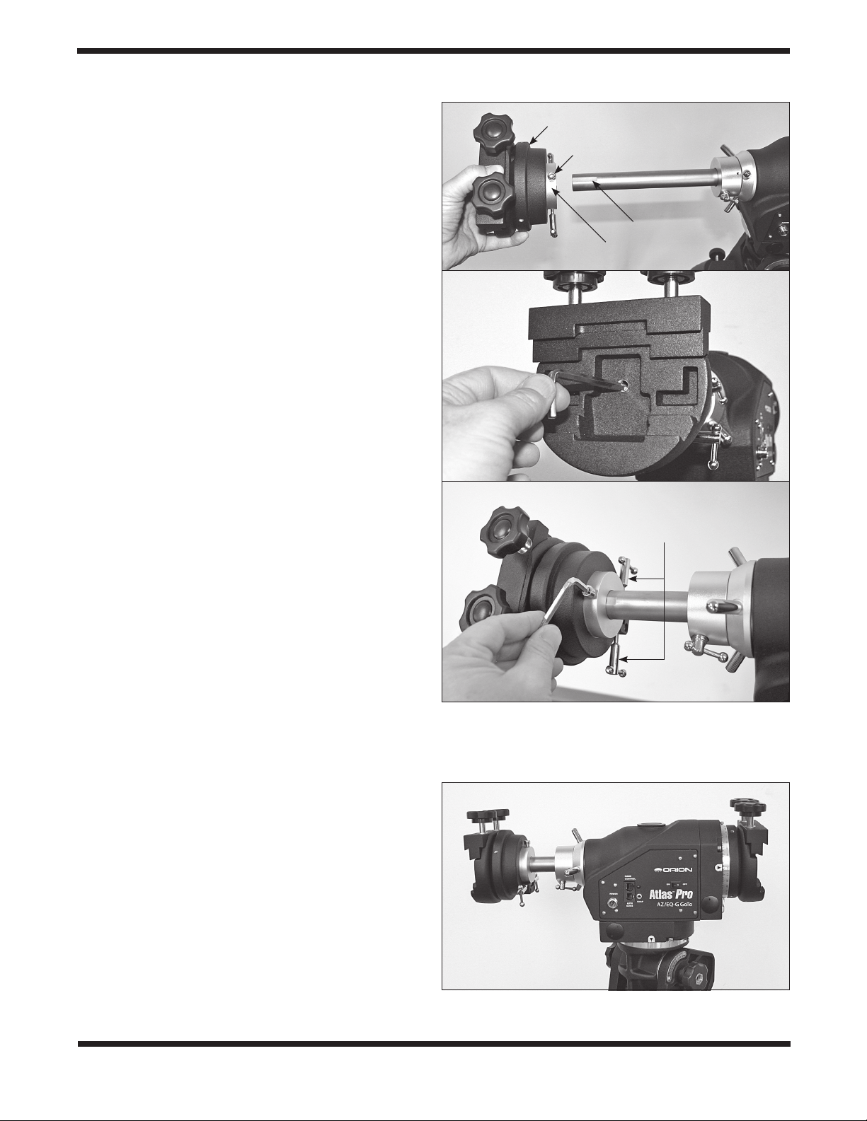
2. Now loosen the counterweight lock knob and slide the
weight(s) along the shaft until it exactly counterbalances
the telescope. That’s the point at which the shaft remains
horizontal even when you let go with both hands. Once
balance is achieved, retighten the counterweight lock
knobs.
3. To balance the telescope on the Dec. axis, rst tighten
the R.A. clutch, with the counterweight shaft still in the
horizontal position. Then with one hand on the telescope
optical tube, loosen the Dec. clutch and check for any
rotation. If there is some, adjust the telescope forward
or back in the saddle or in its tube rings until it remains
horizontal when you carefully let go of it.
The telescope is now balanced on both axes. When you loos-
en the clutch on one or both axes and manually point the tele-
scope, it should move without resistance and should not drift
from where you point it.
3. Using the Atlas Pro
AZ ⁄ EQ-G Mount
3.1 Manually Rotating the Mount
The mount can be moved manually by simply loosening the
R.A. and Dec clutches and pointing the telescope to the
desired location. Both the R.A. and Dec. clutches should be
tightened when driving the mount with the internal motors.
3.2 Using the Setting Circles
As indicated in Figure 11a, the Atlas Pro features right ascen-
sion and declination setting circles. Most users of a GoTo tele-
scope will not have a need to use setting circles, but if you
should, here’s how:
1. Before using the setting circles, they will need to be
calibrated. Point the telescope toward a known object
whose coordinates you have looked up (R.A.-Dec.
coordinates or azimuth-altitude coordinates). Loosen the
two locking thumbscrews on the setting circles and turn
them so the coordinate values line up with the arrows on
both the R.A. and Dec. setting circles, then retighten the
locking screws.
2. Once the setting circles are calibrated, the mount can
be moved either electronically or manually to specied
coordinates by referring to the setting circle readings.
3. The R.A. setting circle features three different scales
(Figure 11b): the upper scale is used to indicate the right
ascension in Equatorial mode when mount is operating
Figure 11. a) R.A. and Dec. setting circles. b) The RA setting
circle features three stacked numbers: top number is R.A. in EQ
mode in Southern hemisphere; middle number is R.A. in EQ mode in
Northern hemisphere; bottom number is azimuth angle in Alt-azimuth
mode. The latitude scale and pointer are used to set the R.A. axis
elevation to the latitude of your observing/imaging location.
Thumbscrew
lock
Thumbscrew
lock
Dec
setting
circle
RA
setting
circle
a.
b.
Latitude
pointer
Latitude
scale
R.A. setting circle
Three
scales

8
in the Southern Hemisphere; the middle scale is used
to indicate the right ascension in Equatorial mode when
operating in the Northern Hemisphere; the lower scale is
used to indicate the azimuth angle when operating in Alt-
azimuth mode.
4. The Dec. setting circle is divided into four quadrants of
90-degrees, used to indicate the declination (when mount
is operating in Equatorial mode) or altitude angle (when
operating in Alt-azimuth mode). Users should use the
proper segment when calibrating the Dec. setting circle.
3.3 Adjusting the R.A. Axis Elevation
(Latitude)
1. Loosen the two altitude lock knobs located on the sides
of the mount (Figure 12).
2. Locate the altitude jackscrew (Figure 13) and extend its
retracted handle. Use it to turn the jackscrew to set the
R.A. axis elevation to your location’s latitude. Refer to the
latitude scale and pointer on the left side of the mount
(Figure 11b). (If you don’t know your latitude, consult
a geographical atlas or look it up on the internet.) For
example, if your latitude is 35° North, set the pointer to
35. The latitude setting should not have to be adjusted
again unless you move to a different viewing location
some distance away.
3. Stow the handle back in the jackscrew after the
adjustment, then tighten the two altitude lock knobs.
Note: It is normal to have slight elevation play on the Atlas
Pro AZ/EQ-G mount. The mount depends on the gravity of its
payload and its own weight to stay rm. Because of this, it is
recommended to end the elevation adjustment with an upward
movement. Whenever there is an upward over-adjustment,
lower the elevation rst, and then crank the mount upward
again.
3.4 Setting the Mount to Alt-azimuth Mode
1. Loosen the two altitude lock knobs (Figure 12).
2. Remove the two knurled knobs from the left side of the
mount (Figure 14a). Put the shorter one into the lower
screw hole; keep the longer one for later usage. Notice
the “Alt-azimuth mode lock hole” in the R.A. axis housing.
You will align that hole with the screw hole to its left when
you orient the mount head in the alt-azimuth position in
the next step.
3. Now crank up the R.A. axis with the jackscrew until it
reaches approximately 88 degrees elevation, at which
Figure 13. The altitude jackscrew with handle a) retracted, and b)
extended for turning.
Figure 12. The dual altitude lock knobs.
Altitude lock
knobs
Jackscrew
with handle
retracted
Handle
extended
a.
b.

9
point the jackscrew will disengage entirely. Lift the
counterweight shaft to align the alt-azimuth mode lock
hole with the upper screw hole on the left side, then
insert the longer knurled knob to connect these two holes
(Figure 14b) and tighten it with the included 5mm Allen
wrench.
4. Retighten the two altitude lock knobs. Figure 15
shows the mount set in Alt-azimuth mode, with one
counterweight installed.
5. To restore the mount to Equatorial mode, loosen the two
altitude lock knobs rst, then remove and exchange the
two knurled knobs on the left side of the mount. While
holding the counterweight shaft, slowly lower the R.A.
axis until the latitude jackscrew starts to engage. Then
turn the jackscrew counterclockwise with the handle to
lower the elevation to the desired angle.
Note:
• When setting the mount to Equatorial mode, the longer
knurled knob on the left side of the mount must rst be
moved to the lower threaded hole on the same side,
otherwise the mount may be damaged when cranking
the R.A. axis down.
• In Alt-azimuth mode with one telescope mounted, the
telescope should be positioned such that it is on the
right-hand side of the mount when viewed from behind
the mount. The counterweight shaft should be extended
to the left.
• When switching between Alt-azimuth and Equatorial
modes, be sure to remove the telescope (rst) and all
counterweights (after scope has been removed) from
the mount rst to avoid damage to the mount’s latitude
adjustment mechanisms.
• It may be more difficult to balance the R.A. (or Azimuth)
axis in Alt-azimuth mode. Here are the balancing steps
recommended for Alt-azimuth mode:
• Balance the payload and counterweights in equatorial
mode and mark the position of the counterweights.
• Unload the payload and counterweights to set the mount
in Alt-azimuth mode.
• Re-load the mount again by installing the counterweights
at the marked position.
Figure 15. Single scope mount setup in Alt-Azimuth mode, with
one counterweight added.
Figure 14. a) The two knurled knobs appear as shown in EQ
mode. b) To use the mount in Alt-azimuth mode, the knob positions
should be switched.
Short
knob
Alt-azimuth
mode lock hole
Long
knob
Long knob
Short knob
a.
b.

10
3.5 Mounting a Second Telescope (Alt-azimuth
mode only)
The secondary telescope saddle (included) can be installed at
the end of the Atlas Pro mount’s counterweight shaft to mount
a second telescope.
1. Slide the counterweight shaft out and rotate it so the at
strip at the end of the shaft is facing up, then lock the
shaft with the T-bolt.
2. Loosen the Allen screw on the secondary saddle’s silver
coupler ring and push the saddle onto the counterweight
shaft, as shown in (Figure 16a). Align the Allen screw
with the at strip on the counterweight shaft.
3. Use a 5mm Allen wrench to secure the saddle to the
counterweight shaft with the Allen screw in the center of
the saddle (Figure 16b). Also tighten the Allen screw on
the coupler ring with the same wrench (Figure 16c).
4. Tighten the Dec. clutch, and then install the second
telescope on the secondary saddle. The second
telescope and its saddle should be situated to the left of
the mount when the telescope points forward.
5. Loosen the counterweight shaft’s locking T-bolt to test the
balance of the second telescope. Adjust the positioning
of the telescope in its tube rings or the dovetail bar’s
position in the groove of the saddle until the telescope is
balanced. Then retighten the T-bolt.
6. Loosen the Dec. clutch to check the balance of the
telescope mounted on the primary saddle. Make any
adjustments needed, then retighten the Dec. clutch.
7. Loosen the counterweight shaft’s locking T-bolt and rotate
the second telescope until it points in the same direction
as the main telescope. Lock the T-bolt again.
8. Aim the main telescope at a distant object, and then
adjust the two vertical-adjustment T-bolts on the
secondary saddle (Figure 16c) to point the secondary
telescope to the same vertical level.
Figure 17 shows the mount in Alt-azimuth mode with the sec-
ondary saddle installed.
Note:
• Use the secondary saddle only when the Atlas Pro
mount is congured in Alt-azimuth mode.
• There is no mechanism on both the primary saddle and
the secondary saddle for aligning the two telescopes in
the azimuth direction.
• The 150mm counterweight shaft extension cannot be
used with the secondary saddle.
Figure 16. a) For mounting a second telescope in Altazimuth
mode, a secondary saddle is installed on the counterweight shaft. b)
Be sure to tighten the screw running through center of the secondary
saddle. c) Finally, tighten the socket head screw on the saddle’s
silver collar.
Secondary saddle
Silver coupler ring
Flat strip
Allen screw
Vertical
adjustment
T-bolts
Figure 17. The mount is now ready to accept two telescopes in
Altazimuth mode.
a.
b.
c.

11
4. Polar Alignment
4.1 What Is It?
When you look at the night sky, you no doubt have noticed that
the stars appear to move slowly from east to west over time.
That motion is actually caused by the Earth’s rotation (from
west to east). An equatorial mount is designed to compensate
for that motion, allowing you to easily “track” the movement of
astronomical objects, thereby keeping them from drifting out of
your telescope’s eld of view while you’re observing or imaging.
This “tracking” is accomplished by slowly rotating the tele-
scope on its right ascension (R.A.) axis (Figure 18), using the
built in motor drive. But rst the R.A. axis of the mount must
be aligned with the Earth’s rotational (polar) axis—a process
called polar alignment.
For Northern Hemisphere operation, approximate polar align-
ment is achieved by pointing the mount’s right ascension axis
at the North Star, or Polaris. It lies within 1° of the north celes-
tial pole (NCP), which is an extension of the Earth’s rotational
axis out into space. Stars in the Northern Hemisphere appear
to revolve around the NCP.
To nd Polaris in the sky, look north and locate the pattern of
the Big Dipper (Figure 19). The two stars at the end of the
“bowl” of the Big Dipper point in the general direction of Polaris.
Observers in the Southern Hemisphere aren’t so fortunate to
have a bright star so near the south celestial pole (SCP). The
star Sigma Octantis lies about 1° from the SCP, but it is barely
visible with the naked eye (magnitude 5.5).
4.2 The Polar Axis Finder Scope
The Atlas Pro mount comes with a polar axis nder scope
(Figure 20) housed inside the right ascension axis of the
mount. When properly aligned and used, it makes accurate
polar alignment quick and easy to do. The polar scope includ-
ed with the Atlas Pro mount can be used for polar alignment
in the Northern or Southern Hemispheres. That is, the polar
scope’s reticle graphic has reference stars that are useful for
aligning in either hemisphere. Remove the cap from the eye-
piece of the polar scope to view through it.
Figure 19. Polaris is easy to nd in the northern sky by extending
an imaginary line from the two “pointer stars” of the Big Dipper.
Polaris lies within 1 degree of the north celestial pole (NCP).
Figure 18. The R.A. and Dec. axes of the Atlas Pro
AZ/EQ-G mount.
Declination axis
Right
ascension
axis
Polar axis
scope
Big Dipper
(in Ursa Major)
Little Dipper
(in Ursa Minor)
Cassiopeia
N.C.P.
Pointer
Stars
Polaris
Figure 20. The polar axis nder scope, which comes preinstalled
in the mount.
Eyepiece
focus ring
Alignment
setscrew (3)
Focus lock
ring
Objective
lens

12
4.3 Aligning the Polar Axis Scope to the R.A.
Axis
Before using the polar scope for polar alignment, the polar
scope itself must be aligned to the mount’s R.A. axis. The reticle
of the polar axis nder scope has a tiny star map printed on it
that makes precise polar alignment quick and easy (Figure 21).
At the center of the reticle is a cross, which you’ll use in the pro-
cedure below to align the polar scope to the R.A. axis.
1. Loosen the Dec. clutch wheel and rotate the optical tube
about the declination axis until you have a clear view
through the polar axis nder scope (Figure 22). Then
retighten the Dec. clutch.
2. Look through the polar scope at a distant object (during
the day) or at Polaris (at night) and center it on the cross
in the middle of the reticle. You may need to adjust the
latitude jackscrew and azimuth adjustment knobs of the
mount and the tripod position to do this. Focus the polar
scope by rotating its eyepiece.
3. Rotate the mount 180° about the R.A. axis. It may
be convenient to remove the optical tube and
counterweights before doing this. If the object remains
centered on the center cross of the reticle after the
rotation, then the polar scope is properly aligned to the
R.A. axis and no adjustment is needed.
4. If the target deviated from the cross, then use a 1.5mm
Allen wrench to adjust the three small Allen screws on
the polar scope (Figure 23a) to move the target half
the distance back to the cross (Figure 23b). Then you
will re-center the object on the cross as in step 2 using
the mount’s azimuth adjustment knobs and the latitude
jackscrew.
5. Repeat steps 2 to 4 until the object stays centered on the
cross of the reticle when rotating the mount on the R.A.
axis.
Note:
• When adjusting the Allen screws, loosen one screw
only ¼ of a turn, and then tighten the other two.
• Do not over tighten the Allen screws as it might damage
the reticle plate in the polar scope.
• Do not loosen one screw completely or loosen more
than one screw at a time, or the reticle plate in the polar
scope will be disengaged and further adjustment is
impossible.
• If the reticle plate does disengage, remove the
polar scope’s eyepiece by turning the knurled ring
counterclockwise and engage the reticle plate again.
4.4 Polar Alignment Using the Polar Scope
1. Set up the Atlas Pro mount. It is recommended to load
the mount with the counterweights and telescope (in that
order!) and level the mount prior to polar alignment.
2. Move the tripod so the telescope tube and right
ascension axis point roughly at Polaris (for Northern
Hemisphere) or toward the four dim stars (approx
magnitude 5 or 6) of Octans (for Southern Hemisphere).
You may need to adjust the altitude and azimuth
adjustments to accomplish this.
3. Loosen the Dec. clutch wheel and rotate the optical tube
about the declination axis until you have a clear view
through the polar axis nder scope (Figure 22). Then
retighten the Dec. clutch.
Figure 21. The reticle of the polar axis scope shows the positions
of the Big Dipper and Cassiopeia relative to Polaris and the north
celestial pole (NCP). For southern hemisphere users, four stars of
the constellation Octans are depicted.
Figure 22. To view through the polar scope, rotate the Dec. axis
of the mount until the opening in the Dec. shaft lines up with the
opening in the mount housing.
Opening in
declination
shaft

13
4. Turn on the power to the mount to illuminate the polar
scope. The reticle pattern (Figure 21) should now be
visible in the polar scope. If the image appears blurred,
rotate the polar scope’s knurled eyepiece to focus it.
Note: The red illumination of the polar scope reticle is adjust-
able from 100% to 0% brightness. The default illumination is
100%, which may be too bright for readily seeing Polaris and
surrounding stars. To reduce the brightness, access the menu
“UTILITY \ Polar Scope LED” and press the ENTER key. Use
the Left direction key to reduce the illumination to the desired
level (probably 10% or less), then press the ENTER key to
set it.
5. Now, sight Polaris in the polar axis nder scope. If it’s not
in the eld of view, move the mount left or right using the
azimuth adjustment knobs, and adjust the altitude up or
down using the jackscrew until Polaris is visible in the
polar scope.
6. Note the constellation Cassiopeia and the Big Dipper in
the reticle. They do not appear in scale, but they indicate
the general positions of Cassiopeia and the Big Dipper
relative to the NCP in the sky. Rotate the reticle so the
star patterns depicted match their current orientation
in the sky when viewed with the naked eye. To do this,
release the R.A. clutch and rotate the main telescope
around the R.A. axis until the reticle is oriented with sky.
For larger optical tubes, you may need to remove the
tube from the mount to prevent it from bumping into the
mount during this procedure.
7. Now use the azimuth adjustment knobs and the latitude
jackscrew on the mount to position Polaris inside the tiny
circle on the nder’s reticle.You must rst loosen – only
very slightly! – the knob underneath the mount head on
the center support shaft to use the azimuth adjustment
knobs. Once Polaris is properly positioned within the
reticle, you are precisely polar aligned. Retighten the
knob under the mount and lightly tighten the altitude lock
knobs on the sides of the mount.
Polar Alignment in Southern Hemisphere: In the eld of
view of the polar scope, locate the four dim stars that form
the pattern labeled “Octans,” which lie near the South Celestial
Pole. Loosen the R.A. clutch and rotate the R.A. axis to align
the orientation of the “Octans” graphic to the same four stars
in the actual sky. Then use the altitude jackscrew and the azi-
muth adjustment knobs to move the four stars into the four
small circles of the Octans graphic on the reticle. With that, the
mount is now polar aligned for Southern Hemisphere viewing.
4.5 Another Way to Determine Position of
Polaris on Reticle
At the end of the initialization of the SynScan hand controller,
after entering the proper local longitude, latitude, date, time,
and daylight-saving time setting, the SynScan hand controller
will display the message: “Polaris Position in P.Scope=HH:MM”.
Imagine the larger circle in Figure 21 as a clock’s face with
12:00 at the top, with the current time pointing to the “HH:MM”.
The orientation of the hour hand of the clock represents the
orientation of Polaris in the polar scope. Place Polaris at the
same orientation on the reticle’s large circle to nish the polar
alignment.
Note: From this point on in your observing or imaging session,
you should not make any further adjustments to the azimuth
or the latitude of the mount, nor should you move the tripod.
Doing so will disrupt the polar alignment. The telescope should
be moved only about its right ascension and declination axes.
Figure 23. a) The polar axis scope has three alignment setscrews
located near the eyepiece. b) After centering a distant target and
rotating the mount 180 degrees in R.A., adjust the three alignment
setscrews to move the target half the distance back to the center
cross. Then use the mount’s latitude jackscrew and azimuth
adjustment knobs to recenter the target.
Alignment
setscrews
(x3)
If Polaris (or daytime
target) drifted to here
Place Polaris (or
daytime target) here
(half the distance)
a.
b.

14
5. Drive Panel Interface
5.1 Drive Panel
The drive panel of the Atlas Pro AZ/EQ-G is shown in Figure
24.
5.2 Panel Interface Components:
POWER: This is a threaded 12V DC power input jack that pro-
vides a secure connection to the power source. The 12V DC
“cigarette lighter” power cable provided with the mount has a
matching threaded connector for the input jack.
HAND CONTROL: This RJ-45 8-pin jack is for connecting the
coil cable of the SynScan hand controller.
AUTO GUIDE: A 6-pin RJ-12 jack is for connecting an autogu-
ider. It is compatible with any autoguider with a ST-4 type
interface.
SNAP: This 2.5mm stereo jack allows connection to a camera’s
shutter control port. The SynScan hand controller can control
a camera to take pictures automatically via this interface. The
camera control cable included with the Atlas Pro mount is com-
patible with select Canon EOS series DSLR cameras. It has
a right angle 2.5mm stereo plug on one end for connection to
the drive panel and a straight 2.5mm plug on the other end for
connection to the camera. Cables for other cameras can be
sourced optionally or custom made.
ON/OFF Switch: Turns on and off the power to the mount and
hand controller.
Power LED: The power LED serves as a power-on indicator
and provides other status information:
1. Steady on: Power voltage is normal.
2 . Slow ashing: Power voltage is low; continuing to operate
the mount may damage the battery (if a 12V lead-acid
battery is in use).
3 . Fast ashing: Power voltage is extremely low; continuing
to operate the mount may damage the battery and the
motor controller in the mount.
4 . Intermittent single ash: The PPEC training routine has
been triggered, but the controller board in the mount has
not received the worm index signal and the PE correction
recording has not started yet.
5 . Intermittent double ash: The PPEC training routine has
been started and the controller board in the mount has
received the worm index signal and started to record the
PE correction. When the intermittent double ash stops, it
means the PPEC training has nished.
6 . Intermittent triple ash: Sidereal tracking with PEC is now
enabled.
5.3 Pinout of the Interfaces
A schematic diagram of the drive panel port circuitry is shown
in Figure 25.
Note:
• The SNAP port provides two trigger signals to the
stereo plug. The signal to the head of the plug is issued
slightly later than the signal to the ring of the plug.
• For a camera that needs only a shutter-release signal,
either trigger signal will work. For a camera that requires
a “Focus” signal ahead of the shutter-release signal,
both signals will be utilized.
5.4 Attaching the SynScan GoTo Hand
Controller
The coil cable for the SynScan hand controller has RJ-45 con-
nectors on each end. Plug one connector into the Hand Control
port of the drive panel and the other connector into the RJ-45
port on the bottom of the SynScan controller (Figure 26). Push
the connector into the port until it clicks into place.
The smaller modular port next to the RJ-45 port on the hand
controller enables serial communication between the Atlas Pro
mount and a computer running astronomy software such as
Starry Night Pro. For that you will need the RS-232 computer
interface cable that was included with the mount. If your com-
puter does not have an RS-232 port, you will also need a USB-
to-serial adapter. Check telescope.com for an available adapter.
5.5 Power Supply Requirements
The Atlas Pro AZ/EQ-G should be powered by a 12V DC or
AC-to-DC power supply with a 3-amp or higher output cur-
rent rating. (A 2A AC adapter of the type recommended for the
Atlas EQ-G mount will not work for the Atlas Pro.)
• Output Voltage: DC 11V (minimum) to DC 16V
(maximum). Voltage not in this range could cause
Figure 24. The drive panel of the Atlas Pro AZ/EQ-G
Power LED

15
permanent damage to the motor controller board or the
hand controller.
• Output Current: 4A for power supply with 11V output
voltage, 2.5A for power supply with 16V output voltage.
• Do not use an unregulated AC-to-DC adapter. When
choosing an AC adapter, it is recommended to use a
switching power supply with 15V output voltage and at
least 3A output current.
• If the power voltage is too low, the motor controller will
stop the motors automatically.
6. Other Atlas Pro AZ/EQ-G
Features
6.1 Auxiliary Encoder Function
The Atlas Pro mount is equipped with auxiliary encoders on
both the R.A. axis and Dec. axis. These enable the mount to
continue tracking even when a user unlocks the clutches and
manually rotates the mount in R.A. and Dec. With this feature,
you can manually operate the mount any time without worry-
ing about losing the mount’s alignment status. When you want
to operate the mount with the SynScan hand controller again,
no re-alignment is required; all that is needed is to re-lock
the clutches. This feature can be enabled or disabled in the
SynScan hand controller.
6.2 Permanent Periodic Error Correction
The Atlas Pro mount is equipped with an index on its R.A. worm,
thus the motor controller can keep tracking the current position
of the worm. After a proper PEC training routine, in which the
training data is stored in the motor controller permanently, a
user can start the periodic error correction (PEC) at any time
to improve the tracking performance for astrophotography. A
training process is not required in the next observing session
(assuming that the polar alignment is always accurate), thus
this is a Permanent Period Error Correction (PPEC). A user can
train the mount by guiding either manually or electronically with
auto-guiding. For detailed instructions, please refer to the rele-
vant section in the SynScan hand controller instruction manual.
6.3 Batch Exposure Function
The Atlas Pro mount is equipped with a SNAP port that can
control the shutter of a DSLR camera (see Figure 24). Working
with the SynScan hand controller’s “Camera Control” function,
you can set the number of exposures and exposure duration
for up to eight different sets of exposures. There is a 2-second
delay between exposures (or longer depending on your cam-
era’s image download time). For detailed information, refer to
the SynScan hand controller instruction manual.
Figure 25. Schematic diagram of the drive panel port circuitry.
2
3
4
1
5
6
7
8
HAND CONTROL
GND
Vpp+
RX(3.3V)
TX(3.3V)
2
3
4
1
5
6
AUTO GUIDE
GND
Vpp+GND
+5V
RA+
RA-
DEC+
DEC-
R
560
C
10uF/25V
SNAP
Optoisolator
GND
POWER
Control Signal
Internal Circuit
GND
TRIGGER
DELAYED
TRIGGER
Figure 26. SynScan hand controller ports.
Serial cable port
(RJ-12)
Hand controller cable
port (RJ-45)

16
Specifications
Product name Atlas Pro AZ/EQ-G Mount
Mount type German equatorial / Alt-azimuth
dual mode
Payload
(Counterwts. excl.) 44 lbs. (20kg)
Saddle type Dual wide (Losmandy) and narrow
(Vixen)
Latitude
adjustment range 10° - 75°, 90°
Azimuth
adjustment range About ±9°
Counterweight 11 lbs. (5kg) each (x2)
Tripod 2-inch stainless steel, 16.5 lbs.
(7.5kg)
Counterweight shaft 25mm Diameter, length 202mm +
150mm extension
Power requirement DC11~16V 4A
Motors 1.8° Hybrid stepper motor
Transmission 180:1 Worm drive + 48:12 timing
beltdrive + 64 micro-step/1.8°
stepper motordrive
Gear ratio 720
Resolution 9,216,000 Counts/rev., approx. 0.14
arc-second
Maximum
slewing speed 4.2 degrees/second
Tracking rates Sidereal, solar, lunar
Tracking modes Alt-azimuth or Equatorial mode
Autoguiding speeds 0.125X, 0.25X, 0.5X, 0.75X, 1X
PEC 100 segments permanent PEC
Polar axis scope Northern or Southern hemisphere,
illuminated
Hand controller SynScan
Database 42,000+ objects
Celestial object
catalogs Messier, NGC, IC, SAO, Caldwell,
Double Star, Variable star, Named
stars, Planets
Pointing accuracy Up to 5 arc-minutes (RMS)
Resolution of aux.
R.A./Dec.axis
encoders 6356 Counts/rev., approx.
3.4 arc-minutes
Weight
(Tripod excluded) 34 lbs. (15.4kg)
Corporate Offices: 89 Hangar Way, Watsonville CA 95076 - USA
Toll Free USA & Canada: (800) 447-1001
International: +1(831) 763-7000
Copyright © 2021 Orion Telescopes & Binoculars.All Rights Reserved. No part of this product instruction or any of its contents
may be reproduced, copied, modied or adapted, without the prior written consent of Orion Telescopes & Binoculars.
AN EMPLOYEE-OWNED COMPANY
One-Year Limited Warranty
This Orion product is warranted against defects in materials or workmanship for a peri-
od of one year from the date of purchase. This warranty is for the benet of the original
retail purchaser only. During this warranty period Orion Telescopes & Binoculars will
repair or replace, at Orion’s option, any warranted instrument that proves to be defec-
tive, provided it is returned postage paid. Proof of purchase (such as a copy of the origi-
nal receipt) is required. This warranty is only valid in the country of purchase.
This warranty does not apply if, in Orion’s judgment, the instrument has been abused,
mishandled, or modied, nor does it apply to normal wear and tear. This warranty gives
you specic legal rights. It is not intended to remove or restrict your other legal rights
under applicable local consumer law; your state or national statutory consumer rights
governing the sale of consumer goods remain fully applicable.
For further warranty information, please visit www.OrionTelescopes.com/warranty.
This manual suits for next models
1
Table of contents
Other Orion Accessories manuals

Orion
Orion StarShoot 52097 User manual

Orion
Orion SkyView Pro GoTo System User manual

Orion
Orion 8450 User manual

Orion
Orion 13008 User manual

Orion
Orion 13032 User manual

Orion
Orion HCCA G27902 User manual

Orion
Orion 8684 User manual

Orion
Orion StarShoot 52053 User manual

Orion
Orion 9768 User manual

Orion
Orion 8727 User manual

Orion
Orion EQ-1 Equatorial Mount 9011 User manual

Orion
Orion PinPoint 40004 User manual

Orion
Orion 6001 User manual

Orion
Orion SkyLine Deluxe User manual

Orion
Orion 13036 User manual

Orion
Orion OR-200W User manual

Orion
Orion 8671 User manual

Orion
Orion STARSHOOT 52173 User manual

Orion
Orion RKS400F-S User manual

Orion
Orion OWP10UBT User manual