Orisec INT-CS User manual

INT-CS
Internal Compact Sounder
Installation Instructions
Wall Tamper
Conduit Entry
Wall Tamper
Lid Tamper
Piezo Cable Feed
High Voltage Area
(when product is sounding)
PCB Screw
Loosen Screw
Push to Learn
PCB Screw
Lid Tamper
LED 4
Push to Learn
LED 1 LED 2
LED 3
Com
BELL D
STB E
TMP FED
TR C
0V B
+12V A
I/02
I/01
Piezo Plug
Piezo Lead
Piezo Plug
JP3. Tamper Feed = 0V
JP3
LEARN
STB TMP
FED
E
TMP .FED=0V
JP4
Designed and Manufactured
in the United Kingdom
www.orisec.co.uk

1
Introduction
The INT-CS Internal Sounder provides 5 programmable high-level alarm sounds along with a
long-life strobe. It can also provide low-level notication tones, for example entry/exit, chime,
warning etc, with multi-coloured LED status indication.
Features
• Orisec Network Compatible
• Piezo (High-Level) for Alarm Sounds
• Piezo (Low-Level) for e.g. Entry/Exit
• Programmable Alarm Sounds
• 2 x Programmable I/O
• Lesson change / School Lockdown Notications
• Multi-Colour LED Indicators
• Long-Life LED Strobe
• Optional Wireless Access Point
• Acts as a Wireless Repeater (with W-AP)
• Grade 2
• Class II

2
1Mounting the INT-CS
To open the internal sounder loosen the locking screw by turning anti-clockwise, then hinge the
front cover up and away from the backplate.
Wall Tamper
Conduit Entry
Wall Tamper
Lid Tamper
Piezo Cable Feed
High Voltage Area
(when product is sounding)
PCB Screw
Loosen Screw
Push to Learn
PCB Screw
Lid Tamper
LED 4
Push to Learn
LED 1 LED 2
LED 3
Com
BELL D
STB E
TMP FED
TR C
0V B
+12V A
I/02
I/01
Piezo Plug
Piezo Lead
Piezo Plug
JP3. Tamper Feed = 0V
JP3
LEARN
STB TMP
FED
E
TMP .FED=0V
JP4
Wall Tamper
Conduit Entry
Wall Tamper
Lid Tamper
Piezo Cable Feed
High Voltage Area
(when product is sounding)
PCB Screw
Loosen Screw
Push to Learn
PCB Screw
Lid Tamper
LED 4
Push to Learn
LED 1 LED 2
LED 3
Com
BELL D
STB E
TMP FED
TR C
0V B
+12V A
I/02
I/01
Piezo Plug
Piezo Lead
Piezo Plug
JP3. Tamper Feed = 0V
JP3
LEARN
STB TMP
FED
E
TMP .FED=0V
JP4

3
Wall Tamper
Conduit Entry
Wall Tamper
Lid Tamper
Piezo Cable Feed
High Voltage Area
(when product is sounding)
PCB Screw
Loosen Screw
Push to Learn
PCB Screw
Lid Tamper
LED 4
Push to Learn
LED 1 LED 2
LED 3
Com
BELL D
STB E
TMP FED
TR C
0V B
+12V A
I/02
I/01
Piezo Plug
Piezo Lead
Piezo Plug
JP3. Tamper Feed = 0V
JP3
LEARN
STB TMP
FED
E
TMP .FED=0V
JP4
Four screw xing holes and eight cable entry locations are provided to aid mounting.

4
Wall Tamper
Conduit Entry
Wall Tamper
Lid Tamper
Piezo Cable Feed
High Voltage Area
(when product is sounding)
PCB Screw
Loosen Screw
Push to Learn
PCB Screw
Lid Tamper
LED 4
Push to Learn
LED 1 LED 2
LED 3
Com
BELL D
STB E
TMP FED
TR C
0V B
+12V A
I/02
I/01
Piezo Plug
Piezo Lead
Piezo Plug
JP3. Tamper Feed = 0V
JP3
LEARN
STB TMP
FED
E
TMP .FED=0V
JP4
Remove the PCB by unscrewing the two screws. Bring the cable into the housing through one
of the cable entry points. Then feed the cable through the slot in the PCB as shown below.
Connect the lead from the piezo to the piezo plug.
Bringing the Cable in
2

5
Wall Tamper
Conduit Entry
Wall Tamper
Lid Tamper
Piezo Cable Feed
High Voltage Area
(when product is sounding)
PCB Screw
Loosen Screw
Push to Learn
PCB Screw
Lid Tamper
LED 4
Push to Learn
LED 1 LED 2
LED 3
Com
BELL D
STB E
TMP FED
TR C
0V B
+12V A
I/02
I/01
Piezo Plug
Piezo Lead
Piezo Plug
JP3. Tamper Feed = 0V
JP3
LEARN
STB TMP
FED
E
TMP .FED=0V
JP4
PCB and Connections
3
Orisec
Control Panel
or Zone
Expander
Network
Conections
++
INT-CS
Internal
Compact
Sounder
Network Connection
For full functionality connect the INT-CS to the
Network Connections on an Orisec alarm system.
Conventional Connection
The INT-CS can operate as a simple conventional sounder and
strobe when connected to other manufacturers’ control panels.
*These sounds could be used to indicate eg I/O1 “School Lockdown”
and I/O2 “Lesson Changeover”.
I/O1 has priority over I/O2. These notications operate only when used in
conventional stand-alone mode (ie not connected via the network or W-AP).
Ensure JP3 is NOT tted.
Terminal Connect to Control Panel
I/01 Slow Sweep and/or RED LED* (0V applied)
COM Common/0V for IO/1 and I/02
I/02 ‘Beep-beep-beep’ and/or GREEN LED* (0V applied)
12V A +12V supply
0V B 0V supply
TR C Tamper return
BELL D Sounder trigger 0V applied
STB EStrobe trigger 0V applied
TMP FED Tamper Feed

6
Wall Tamper
Conduit Entry
Wall Tamper
Lid Tamper
Piezo Cable Feed
High Voltage Area
(when product is sounding)
PCB Screw
Loosen Screw
Push to Learn
PCB Screw
Lid Tamper
LED 4
Push to Learn
LED 1 LED 2
LED 3
Com
BELL D
STB E
TMP FED
TR C
0V B
+12V A
I/02
I/01
Piezo Plug
Piezo Lead
Piezo Plug
JP3. Tamper Feed = 0V
JP3
LEARN
STB TMP
FED
E
TMP .FED=0V
JP4
Optional W-AP
4
An optional wireless access point W-AP is available separately.
The W-AP can be used for:
• Wireless Activation of the INT-CS
• Wireless Repeater Functionality
NOTE: Do not add/ remove the W-AP whilst the INT-CS is powered.

7
5Simple Enrolment
On the control panel:
1. Enter engineering mode
2. Select “setup wireless zones”
3. Highlight required zone
4. Scroll down to “ID”
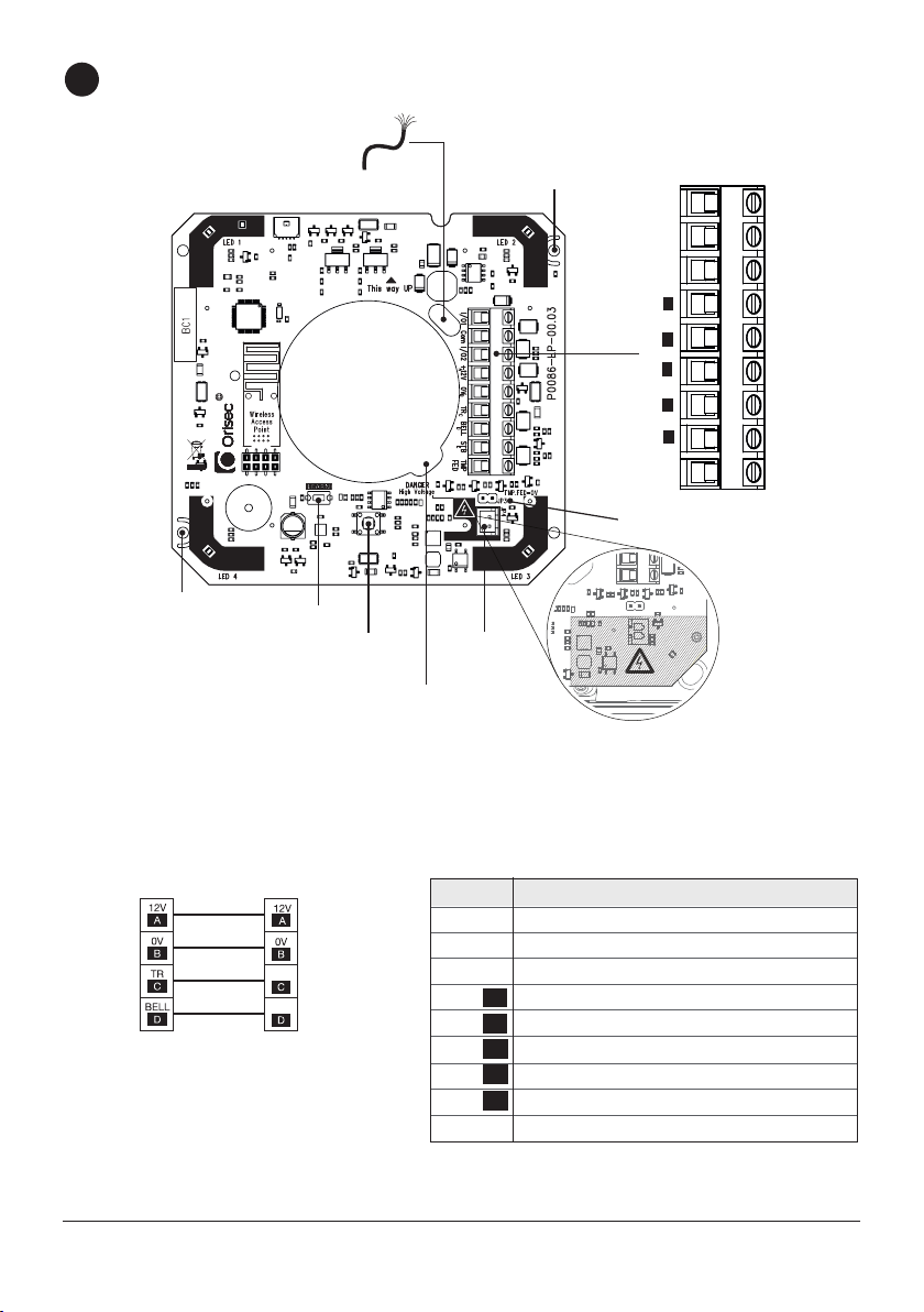
5. Press and hold “Learn” whilst applying power then release
6. Press and hold “Learn” button for 1-2 seconds
Once the INT-CS has been learned to the control panel the unit will automatically operate as a
wireless repeater. Products that can act as repeaters cannot themselves be repeated. For a full
list of products that can be repeated please see this link: www.orisec.co.uk/compatible-products
NOTE: The INT-CS can only be assigned to zones 1-50 on the control panel. It is highly
recommended to leave an available slot each side of the INT-CS. For Tamper monitoring on
the W-XP-R the zone type must be programmed as “Wireless Tamper”. On the keypad: Enter
engineering mode, Select “Programming menu”, Select “Zone programming”, Scroll to the
INT-CS zone, Select Zone Type 32 “Wireless Tamper”
The signal strength can be shown by activating the lid tamper switch and is indicated by the
colour of the LEDs:
• Green = Strong Signal
• Orange = Medium Signal
• Red = Low Signal
Programmable Speaker Tones:
When the INT-CS is connected to the Orisec control panel via the W-AP the onboard speaker
can be enabled for the following dierent tones in the “Setup Wireless Zones” menu:
• Alarm Tones
• Fault Tones
• Chime Tones
• Entry Tones
• Exit Tones
• Advisory Tones
• Tamper Alarms
NOTE: the OMIT key on the keypad is used to enable/ disable tones.

8
To enter programming mode Press & HOLD the learn button until LED 1 is lit only (approx. 5s).
The colour of this will now indicate the selected option (see table below). To change the option,
press the tamper switch. To accept the option and move to the next menu press the learn
button again. Four menus are available, indicated on LEDs 1 to 4. To exit programming menu
press and HOLD the learn button again, or it will time out after 30 seconds of no activity.
Program Options
6
Wall Tamper
Conduit Entry
Wall Tamper
Lid Tamper
Piezo Cable Feed
High Voltage Area
(when product is sounding)
PCB Screw
Loosen Screw
Push to Learn
PCB Screw
Lid Tamper
LED 4
Push to Learn
LED 1 LED 2
LED 3
Com
BELL D
STB E
TMP FED
TR C
0V B
+12V A
I/02
I/01
Piezo Plug
Piezo Lead
Piezo Plug
JP3. Tamper Feed = 0V
JP3
LEARN
STB TMP
FED
E
TMP .FED=0V
JP4
LED Menu Options LED
1 Internal Sounder Address On Network Address 1
Network Address 2
Mode Address 3
Address 4
1 Input 1 & 2 Sounder / LED Option Sounds & LEDs
Conventional I/P 1 Sound Disabled:
Mode I/P 2 Sound Disabled:
I/P 1 & 2 Sound Disabled:
2 Sound Generated When BELL is Triggered Sound 1
Sound 2
Sound 3
Sound 4
Sound 5
3 Light Ring On Time Off
On
10 sec
30 sec
60 sec
4 Light Ring Colour When Bell Is Triggered Red
Green
Blue
Pink
Orange
White
Orisec Blue
The colour you choose will be the colour of the LED ring,
7 colours to choose from
Bold indicates default settings

9
Specications
Electrical
Supply Voltage: 9 - 16 VDC (13.7 V nominal)
Current Consumption:
Idle: 20mA at 9.0V, 28mA at 16.0V
Strobe: 20mA
Siren: 300mA at 9.0V, 190mA at 16.0V
Network: 4-wire standard 7/0.2 alarm cable up to 500m.
I/O Channels: 2; Each programmable as zone input or 100mA output.
Environmental
Operating Temperature: -10°C to +55°C
Storage Temperature: -20°C to +60°C
Max. Humidity: 95% non-condensing
Physical
Product Weight: 250g
Packed Weight: 400g
Dims: (hwd) mm 120 x 120 x 50
Material: 3mm ASA
Certificate No. GB2005228
Registration No. 0044/1
BS EN ISO 9001 : 2015
Registered Firm
Registered Firm
International
International
Accreditation Board
Accreditation Board

Standards
Security
PD 6662:2017
EN 50131-1:2006+A3:2020
EN 50131-4:2019 Type: Remotely Powered, Sweeping Tone
Grade 2, Class II
EMC
Conforms to European Union (EU) Electro-Magnetic Compatibility (EMC) Directive 2014/30/EU
and EN 50130-4:2011+A1:2014
EMC Environment: Residential / Commercial / Light Industrial / Industrial
WEEE Directive: 2012/19/EU Compliant: This symbol indicates that according to local laws and regulations,
this product should not be disposed of as municipal/household waste. Instead, it should be disposed of
at the appropriate collection points designated for the recycling of electrical and electronic equipment,
or returned to Orisec upon purchase of new replacement products. This will help to conserve natural
resources and ensure that it is recycled in a manner that protects human health and the environment.
RoHS Directive: 2011/65/EU Compliant:
Orisec declares that this product complies with and conforms to RoHS legislation that it does
not contain more than the agreed levels of: Lead (Pb), Cadmium (Cd), Mercury (Hg), Hexavalent
chromium (Cr6+), Polybrominated biphenyls (PBB), Polybrominated diphenyl ethers (PBDE)
Manufacturer: Orisec Ltd, 1 St Crispin Way, Haslingden, Lancashire. BB4 4PW. United Kingdom.
Warranty
The INT-CS is guaranteed against defects in material or faulty workmanship for a period of 2
years from the date of purchase.
Disclaimer: Orisec will not accept any liability based on a claim that the INT-CS failed to
perform correctly as it is a component part of an installation and not a complete intruder alarm
system.

www.orisec.co.uk
UK Based Technical Support:
t: +44 (0) 1706 398740
© Copyright Orisec Ltd 2021
INS128
Table of contents
Popular Marine Equipment manuals by other brands

MARINE PROPELLER
MARINE PROPELLER JPROP Use and maintenance handbook

Dual
Dual MXD662B Installation & owner's manual

Klaxon
Klaxon Nexus 105 DC installation instructions

Garmin
Garmin Gladiator TR-1 owner's manual

Daikin
Daikin LXE10E -A33 Service manual

Bennett
Bennett BOLT Rocker BRC4000 Installation and quick start manual