CHARACTERISTICS
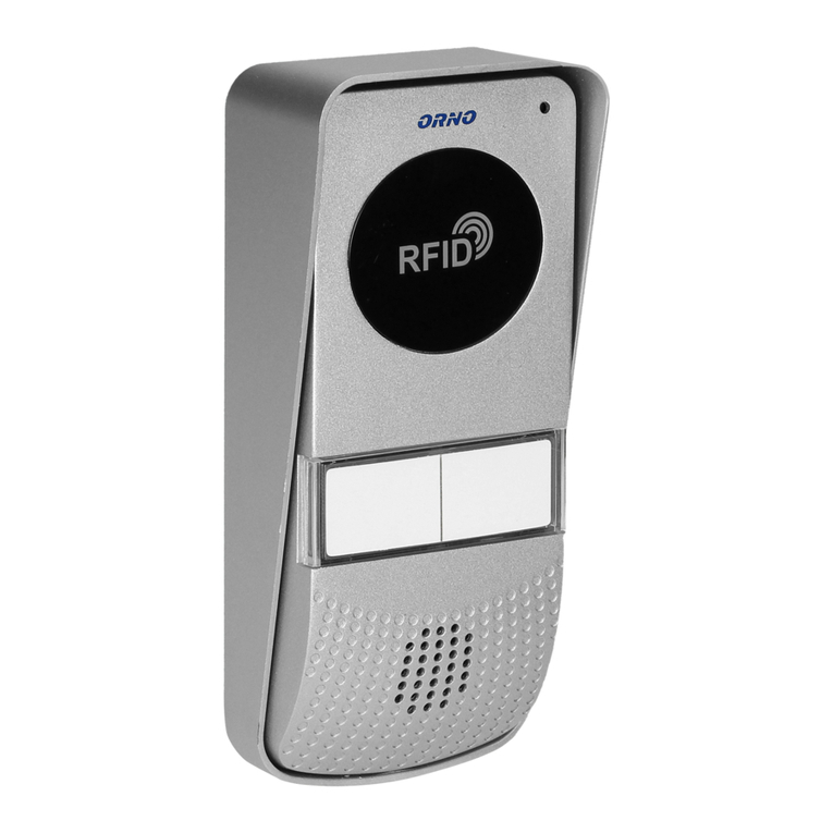
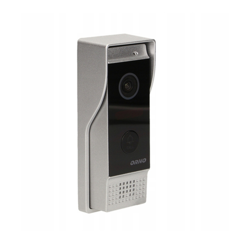
The doorphone OR-DOM-RL-913 is intended for installation in single-family buildings.
Main features of the doorphone:
- flush or surface mounting (with a protective rain cover)
- uniphone with a built-in power supply and a power supply cord,
no additional power supply for the electric strike
12
1. Microphone
2. Call button
3. Protective rain cover
4. Loudspeaker
5. Light diode
6. Handset
7. Door/wicket opening button
8. Power supply cord
9. Cable to connect the handset with the
uniphone
10. External panel holes for wall installation.
6
7
8
9
4
10 5
2
1
CONSTRUCTION
3
INTRODUCTION
Before the installation and use of the device, please read this operation manual carefully. In case of any problems with understanding
the manual, please contact the seller from whom you bought the device. Installation and commissioning of the equipment by the
customer are possible if the installer has basic knowledge of electrical systems and the use of proper tools. Nevertheless, the device
installation by qualified personnel is recommended.
The manufacturer is not liable for any damage that can result from improper installation or operation of the device.
Performing repairs or modifications by the customer voids the warranty.
Since the technical data is subject to continuous modification, the manufacturer reserves the right to modify product specifications or
introduce other design solutions that do not impair product performance or usability.
Additional information on ORNO products is available at: www.orno.pl. Orno-Logistic Sp. z o.o. is not liable for consequences resulting
from failure to comply with the recommendations found in this manual. Orno-Logistic Sp. z o.o. reserves the right to make changes to
the instruction – current version can be downloaded from www.orno.pl. Any rights to translate/construe and the copyright of this
manual are reserved.
1. Disconnect the power supply before performing any activities.
2. Do not immerse the product in water or other liquids.
3. Do not operate the device with damaged housing.
4. Do not open or repair the device yourself.
5. Do not use the appliance for any other purpose than intended.
Operating Instruction
EN
1. Pressing the call button on the external unit generates a sound signal in the uniphone.
2. Pick up the handset to start talking and open the wicket remotely by pressing the opening button on the
uniphone.
O P E R A T I O N
fig. 1 Connection diagram
CONNECTION DIAGRAM
(optional)
INSTALLATION
The correct location of the external panel ensures comfortable device operation. It is recommended to
experimentally choose the best possible location for the device prior to drilling the mounting holes.
The external panel is suitable for flush mounting or for surface mounting with a protective rain cover.
1. Remove the two rubber caps from the outer panel.
2. In the case of flush mounting, insert the outer panel into the cut-out hole in the wall and then mark the
location of two mounting pins through the holes in the panel.
3. Drill two holes and insert the mounting pins into the holes.
4. Connect the 2 cable wires from the panel to the handset using a standard terminal block.
5. Once again place the panel in the prepared wall opening and secure it with 2 screws.
Do not make any connections if the device is connected to a 230 V network!
Failure to follow these instructions may result in damage to the appliance!
red
black
EXTERNAL PANEL
While designing the wiring system, take into account the suitable cross-section of cables:
up to 30 m – recommended cable – XzTKMXpw 3×2×0.5 mm2
from 30 m do 100 m – recommended cable – XzTKMXpw 3×2×0.8 mm2
Connection to the electromagnetic striker must be made with a 2×0.8 mm2 cable.
Any 12 VDC electric striker with a max current draw of 500 mA can be connected to the set.
We do not recommend the use of twisted cables of computer type.
Cables and an electric striker are not included in the set.
UNIPHONE
ELECTRIC STRIKER
