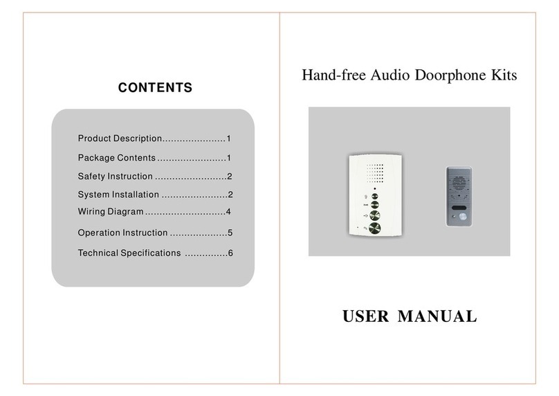
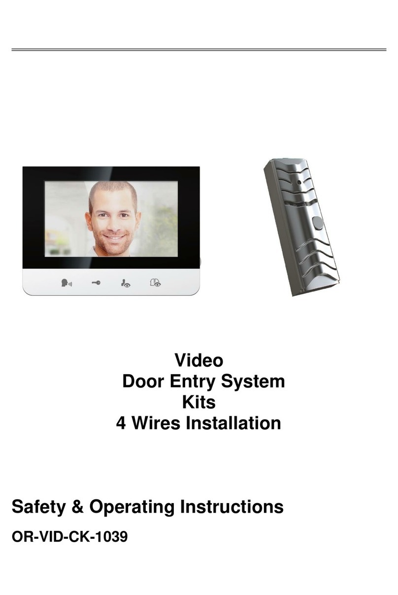
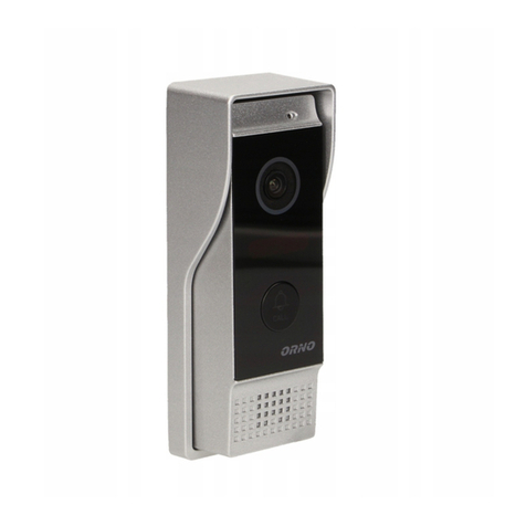
Orno OR-DOM-AT-930/W User manual

ORNO-LOGISTIC Sp. z o.o.
ul. Rolników 437, 44-141 Gliwice, tel. 32 43 43 110, www.orno.pl
PRODUCENT
DWURODZINNY ZESTAW DOMOFONOWY
MIZAR MULTI RFID
INSTRUKCJA OBSŁUGI I MONTAŻU
Model: OR-DOM-AT-930/W

Przed podłączeniem i użytkowaniem urządzenia prosimy o dokładne zapoznanie się z niniejszą instrukcją obsługi
W razie jakichkolwiek problemów ze zrozumieniem jej treści prosimy o skontaktowanie się ze sprzedawcą urządzenia. Samodzielny
montaż i uruchomienie urządzenia jest możliwe pod warunkiem posiadania przez montażystę podstawowej wiedzy z zakresu elektryki i
używania odpowiednich narzędzi. Niemniej zalecane jest dokonanie montażu urządzenia przez wykwalifikowany personel.
Producent nie odpowiada za uszkodzenia mogące wyniknąć z nieprawidłowego montażu czy eksploatacji urządzenia.
Dokonywanie samodzielnych napraw i modyfikacji skutkuje utratą gwarancji.
Z uwagi na fakt, że dane techniczne podlegają ciągłym modyfikacjom, Producent zastrzega sobie prawo do dokonywania zmian
dotyczących charakterystyki wyrobu oraz wprowadzania innych rozwiązań konstrukcyjnych niepogarszających parametrów i walorów
użytkowych produktu.
Najnowsza wersja instrukcji do pobrania na stronie www.orno.pl. Wszelkie prawa do tłumaczenia/interpretowania oraz prawa autorskie
niniejszej instrukcji są zastrzeżone.
1. Wszelkie czynności wykonuj przy odłączonym zasilaniu.
2. Nie zanurzaj urządzenia w wodzie i innych płynach.
3. Nie obsługuj urządzenia gdy uszkodzona jest obudowa.
4. Nie otwieraj urządzenia i nie dokonuj samodzielnych napraw.
5. Nie używaj urządzenia niezgodnie z jego przeznaczeniem.
Zabrania się dokonywania podłączeń urządzeń będących pod napięciem!
Nie przestrzeganie powyższego zalecenia może doprowadzić do trwałego uszkodzenia urządzenia.
OSTRZEŻENIE
Każde gospodarstwo jest użytkownikiem sprzętu elektrycznego i elektronicznego, a co za tym idzie potencjalnym
wytwórcą niebezpiecznego dla ludzi i środowiska odpadu, z tytułu obecności w sprzęcie niebezpiecznych substancji,
mieszanin oraz części składowych. Z drugiej strony zużyty sprzęt to cenny materiał, z którego możemy odzyskać surowce
takie jak miedź, cyna, szkło, żalazo i inne.
Symbol przekreślonego kosza na śmieci umieszczany na sprzęcie, opakowaniu lub dokumentach do niego dołączonych
oznacza, że produktu nie wolno wyrzucać łącznie z innymi odpadami. Oznakowanie oznacza jednocześnie, że sprzęt
został wprowadzony do obrotu po dniu 13 sierpnia 2005 r.
Obowiązkiem użytkownika jest przekazanie zużytego sprzętu do wyznaczonego punktu zbiórki w celu właściwego jego
przetworzenia. Informacje o dostępnym systemie zbierania zużytego sprzętu elektrycznego można znaleźć w punkcie
informacyjnym sklepu oraz w urzędzie miasta/gminy.
Odpowiednie postępowanie ze zużytym sprzętem zapobiega negatywnym konsekwencjom dla środowiska naturalnego
i ludzkiego zdrowia!
04/2020
Instrukcja obsługi
PL
2
PANEL ZEWNĘTRZNY
Zasilanie:
Sposób montażu panela zewnętrznego:
Temperatura pracy:
Wymiary zewnętrzne:
UNIFON
Zasilanie:
Pobór mocy:
Wymiary zewnętrzne (szer.xwys.xgł.):
Ilość dźwięków dzwonka:
Funkcje dodatkowe:
13,5V DC z unifonu
natynkowy
0 0
-15 C ~+50 C
74,5 x 165 x 40 mm (szer./wys./gł.)
zasilacz 13,5VDC 1500mA
czuwanie <0,3W, praca <7,5W
83 x 180 x 41 mm (szer./wys./gł.)
1
regulacja głośności wywołania (wspólnie z panelem
zewnętrznym)
8. DANE TECHNICZNE
9. CZYSZCZENIE I KONSERWACJA
Zabrudzenia należy czyścić miękką lekko wilgotną szmatką z dodatkiem łagodnych środków myjących
przeznaczonych do tworzywa sztucznego.
Nie należy używać środków myjących opartych na bazie rozpuszczalników, benzyny itp. oraz środków
zawierających substancje ścieralne.
7

Zestaw domofonowy przeznaczony jest do montażu w budynkach dwurodzinnych, firmach, szkołach,
przedszkolach, szpitalach itp. Umożliwia zdalne prowadzenie rozmowy pomiędzy panelem zewnętrznym,
a unifonem oraz bezpośrednie sterowanie ryglem elektromagnetycznym oraz bramą.
Najważniejsze cechy domofonu:
- panel zewnętrzny przystosowany do montażu natynkowego (daszek ochronny w zestawie);
- czytnik breloków zbliżeniowych (8 breloków użytkownika i 2 breloki administratora w zestawie);
- regulacja głośności dzwonka;
- bezpośrednie sterowanie elektrozaczepem;
- dodatkowe sterowanie bramą;
- funkcja interkomu po zastosowaniu dodatkowego unifonu;
- możliwość rozbudowy o dodatkowy unifon.
1. Głośnik
2. Mikrofon
3. Przycisk interkomu
4. Przycisk otwarcia bramy
5. Przycisk otwarcia drzwi/furtki
6. Gniazdo zasilania
7. Regulacja głośności dzwonka
8. Gniazdo do podłączenia
automatyki bramy
9. Gniazdo do podłączenia panelu
zewnętrznego
10. Gniazdo do podłączenia
dodatkowego unifonu
rys. 1 Budowa panelu zewnętrznego
rys. 2 Budowa unifonu
2.2 Budowa unifonu - jednostki wewnętrznej
1. CHARAKTERYSTYKA I PRZEZNACZENIE
2.1. Budowa panelu zewnętrznego
1. Przycisk resetowania/
programowania breloków
6
Naciśniecie przycisku wywołania na panelu zewnętrznym (2) jest sygnalizowane dźwiękiem dzwonka na unifonie.
Po podniesieniu słuchawki można prowadzić rozmowę z odwiedzającym.
W celu zdalnego otwarcia furtki należy podczas rozmowy z panelem zewnętrznym, nacisnąć krótko przycisk (5)
na unifonie.
6. OBSŁUGA
1. Programowanie breloków zbliżeniowych
Urządzenie wyposażone jest w funkcję otwierania wejścia za pomocą specjalnego breloka zbliżeniowego.
Przygotuj dwa breloki - czerwony i szary. Jeden z nich - RESET KEY (czerwony) - kasuje aktywny brelok
użytkownika, drugi - ADDING KEY (szary) - programuje breloki użytkowania. Zwróć uwagę by opisać je
prawidłowo.
Gdy domofon jest włączony wciśnij przycisk RESET umieszony z tyłu panelu zewnętrznego, usłyszysz
6 - krotny sygnał dźwiękowy. Przyłóż brelok czerwony do obszaru czytnika, usłyszysz 6-krotny sygnał dźwiękowy.
Następnie przyłóż brelok szary do obszaru czytnika, aż usłyszysz pojedynczy, długi sygnał dźwiękowy. W ten
sposób breloki ADDING i RESET zostaną zaprogramowane.
Dodawanie użytkownika:
By dodać użytkownika najpierw przyłóż brelok ADDING do czytnika (usłyszysz 4 - krotny sygnał dźwiękowy),
a później brelok, który chcesz dodać. Odczekaj ok. 10 sek (usłyszysz pojedynczy sygnał dźwiękowy). Brelok
zostanie zaprogramowany i w trakcie jego użycia będzie słychać pojedynczy sygnał dźwiękowy. Urządzenie
obsługuje breloki RESET i ADDING oraz do 10 breloków użytkowników. Dodanie kolejnych nie będzie możliwe.
RESET breloków:
Przyłóż brelok RESET KEY do strefy czytnika, usłyszysz 4 - krotny sygnał dźwiękowy, spowoduję to skasowanie
wszystkich używanych breloków. Następnie przyłóż do czytnika brelok ADDING by zaprogramować nowe breloki.
Jeżeli po przyłożeniu breloka RESET w ciągu 10 sek. nie zostanie wykonana jakaś akcja, breloki pozostaną
zaprogramowane i będą działały tak jak do tej pory.
7. OBSŁUGA CZYTNIKÓW RFID
3
1 2
1 2
1. Mikrofon
2. Kołyskowy przycisk wywołania
3. Głośnik

4 5
1. Wywierć w ścianie 2 otwory i umieść w nich kołki
montażowe
2. Do gniazd łączeniowych znajdujących się na odwrocie
unifonu podłącz przewody zgodnie ze schematem
podłączenia.
3. Zamocuj tylną część unifonu na przykręconych do ściany
śrubach.
4. Zawieś słuchawkę na podstawie.
5. Podłącz zasilacz do sieci 230VAC, 50Hz.
Właściwe umiejscowienie panelu zewnętrznego decyduje o komforcie pracy z urządzeniem. Zaleca się przed
wykonaniem otworów montażowych przetestowanie urządzenia. W tym celu nie należy umieszczać panelu
zewnętrznego oraz unifonu w tym samym pomieszczeniu, gdyż mogą się tworzyć sprzężenia.
Panel zewnętrzny przystosowany jest do montażu natynkowego.
3.1. Instalacja panelu zewnętrznego
3.2. Instalacja unifonu (jednostki wewnętrznej)
Zestaw nie zawiera elektrozaczepu oraz automatu sterowania bramą!
rys. 3 Montaż panelu zewnętrznego
rys. 4
1. Wywierć dwa otwory w ścianie/słupku, w miejscu gdzie ma zostać zamontowany panel zewnętrzny
2. Umieść kołki rozporowe w przygotowanych otworach.
3. Przyłóż daszek w miejscu instalacji.
4. Przykręć śruby mocujące.
5. Załóż kasetę zewnętrzną.
Montaż natynkowy
ściana
ściana
4. SCHEMAT PODŁĄCZENIA
4.1. Schemat podłączenia zestawu z elektrozaczepem
rys. 5 Schemat podłączenia
5. ROZBUDOWA ZESTAWU
5.1. Schemat podłączenia dwóch unifonów
Projektując instalację elektryczną należy uwzględnić odpowiedni przekrój przewodów:
2
do 30 m - zalecany przewód XzTKMXpw 3 x 2 x 0,5 mm
2
od 30 m do 100 m - zalecany przewód XzTKMXpw 3 x 2 x 0,8 mm
2
Połączenie z ryglem elektromagnetycznym powinno być przeprowadzone przewodem 2 x 1 mm .
Z zestawem poprawnie współpracuje dowolny elektrozamek o napięciu zasilania 12VDC i poborze
prądu max. 500 mA.
Całkowita długość instalacji nie może przekroczyć 100 metrów.
Absolutnie nie zaleca się stosowania przewodów typu skrętka komputerowa.
Zestaw nie zawiera elektrozaczepu oraz automatu sterowania bramą i unifonu!
rys. 6 Schemat podłaczenia
elektrozaczep
(wyposażenie dodatkowe)
elektrozaczep
(wyposażenie dodatkowe)
Panel zewnętrzny
Panel zewnętrzny
Opcja
sterowania
bramą
Opcja
sterowania
bramą
Unifon 1
Unifon 1 główny
Unifon 2 główny
Unifon 2
Unifon 1 dodatkowy
Unifon 2 dodatkowy
zasilanie (B+)
masa (G)
audio (A)

ORNO-LOGISTIC Sp. z o.o.
ul. Rolników 437, 44-141 Gliwice, tel. 32 43 43 110, www.orno.pl
PRODUCER
TWO-FAMILY INTERCOM SYSTEM
MULTI RFID MISAR
INSTALLATION AND OPERATION MANUAL
Model: OR-DOM-AT-930/W
INSTALLATION AND OPERATION MANUAL

Before the installation and use of the device, please read this operation manual carefully. In case of any problems with understanding the
manual, please contact the seller from whom you bought the device. Installation and commissioning of the equipment by the customer are
possible if the installer has basic knowledge of electrical systems and the use of proper tools. Nevertheless, the device installation by
qualified personnel is recommended.
The manufacturer is not liable for any damage that can result from improper installation or operation of the device.
Performing repairs or modifications by the customer voids the warranty.
Since the technical data is subject to continuous modification, the manufacturer reserves the right to modify product specifications or
introduce other design solutions that do not impair product performance or usability.
Current version can be downloaded from www.orno.pl. Any rights to translate/construe and the copyright of this manual are reserved.
1. Disconnect the power supply before performing any activities.
2. Do not immerse the product in water or other liquids.
3. Do not operate the device with damaged housing.
4. Do not open or repair the device yourself.
5. Do not use the appliance for any other purpose than intended.
It is forbidden to make connections to live devices!
Failure to comply with the above recommendations may result in permanent damage to the device.
WARNING
Each household is a user of electrical and electronic equipment, and hence a potential producer of hazardous waste for
humans and the environment, due to the presence of hazardous substances, mixtures and components in the equipment.
On the other hand, used equipment is valuable material from which we can recover raw materials such as copper, tin,
glass, iron and others.
The weee sign placed on the equipment, packaging or documents attached to it indicates the need for selective collection
of waste electrical and electronic equipment. Products so marked, under penalty of fine, cannot be thrown into ordinary
garbage along with other waste. The marking means at the same time that the equipment was placed on the market after
August 13, 2005. It is the responsibility of the user to hand the used equipment to a designated collection point for proper
processing. Used equipment can also be handed over to the seller, if one buys a new product in an amount not greater than
the new purchased equipment of the same type. Information on the available collection system of waste electrical
equipment can be found in the information desk of the store and in the municipal office or district office.
Proper handling of used equipment prevents negative consequences for the environment and human health!
04/2020
Operang Instrucon
EN
2
EXTERNAL PANEL
Supply voltage:
Mounting method:
Working temperature:
Dimensions:
UNIPHONE
Supply voltage:
Power consumption:
Dimensions:
Number of ringtones:
Additional functions:
13.5V DC from uniphone
surface-mounted
0 0
-15 C ~+50 C
74.5 x 165 x 40 mm
13.5VDC 1500mA power unit
standby mode <0,3W, working mode <7,5W
83 x 180 x 41 mm
1
Call volume adjustment (together with the external panel)
8. TECHNICAL DATA
9. CLEANING AND MAINTENANCE
The dirt should be cleaned with a soft, slightly damp cloth with the addition of mild cleaning agents intended for
plastic.
Do not use cleaning agents based on solvents, gasoline, etc. and agents containing abrasive substances.
7
INTRODUCTION

The intercom set is designed for installation in two-family buildings, companies, schools, kindergartens, hospitals,
etc. It enables remote conversation between the external panel and the uniphone and direct control of the
electromagnetic strike and gate.
The most important features of the intercom:
- external panel suitable for surface mounting (protective cover included);
- proximity tag reader (8 user key rings and 2 administrator key rings included);
- ring tone volume adjustment;
- direct control of the electric striker;
- additional gate control;
- intercom function after using additional uniphone;
- possibility of expanding with an additional uniphone.
1. Microphone
2. Call button
3. Loudspeaker
1. Loudspeaker
2. Microphone
3. Intercom button
4. Gate opening button
5. Door/wicket opening button
6. Power supply socket
7. Ring tone volume adjustment
8. Socket for gate automation
9. Socket for external panel
10. Socket for additional uniphone
fig. 1 Construction of the external panel
fig. 2 Construction of the uniphone
2.2 Construction of the uniphone - internal unit
1. CHARACTERISTICS AND DESTINATION
2.1. Construction of the external panel
1. Reset/programming
key rings
6
Pressing the call button on the external panel (2) is indicated by the ringing tone on the uniphone.
When you pick up the handset, you can talk to the visitor.
To open the gate remotely, while talking to the external panel, shortly press button (5) on the uniphone.
6. OPERATION
1. Programming of proximity tags
The device is equipped with a function of opening the entrance with a special key ring.
Prepare two key rings - red and grey. One of them - RESET KEY (red) - deletes the active user key ring, the other -
ADDING KEY (grey) - programs user key rings. Make sure to describe them correctly.
When the intercom is on, press the RESET button on the back of the external panel, you will hear beep 6-times.
Put the red key ring on the reader area, you will hear beep 6-times. Then put the grey key ring on the reader area
until you hear a single, long beep. In this way the ADDING and RESET key rings will be programmed.
Adding a user:
To add a user, first put the ADDING key ring on the reader (you will hear beep 4-times) and then the key ring you
want to add. Wait about 10 seconds (you will hear single beep). The key ring will be programmed and single beep
will be heard during its use. The device supports RESET and ADDING key rings and up to 10 user key rings. It will
not be possible to add more.
RESET key rings:
Put the RESET KEY in the reader area, you will hear beep 4-times, this will delete all used key rings. Then put the
ADDING key on the reader to program new key rings. If no action is performed after applying the RESET key within
10 seconds, the key rings will remain programmed and will work as before.
7. OPERATION OF RFID READERS
3
2. CONSTRUCTION
1 2
1 2

4 5
1. Drill 2 holes in the wall and place mounting screws in them.
2. Connect the cables to the connection sockets on the back
of the uniphone according to the connection diagram.
3. Fix the back of the uniphone to the wall mounted screws.
4. Hang up the handset on the base.
5. Connect the power supply to 230VAC, 50Hz.
The correct location of the external panel ensures comfortable device operation. It is recommended to
experimentally choose the best possible location for the device prior to drilling the mounting holes. To do this, do not
place the external panel and the uniphone in the same room, as feedback may form.
The external panel is suitable for surface mounting.
3.1. Installation of external panel
3.2. Installation of the uniphone (indoor unit)
The set does not include an electric strike and automatic gate control unit!
fig. 3 Installation of the external panel
fig. 4
1. Drill two holes in the wall/post where the external panel is to be mounted.
2. Place the mounting screws in the prepared holes.
3. Put the protective cover in the place of installation.
4. Tighten the mounting screws.
5. Put the outer cassette on.
Surface mounting
wall
wall
4. WIRING DIAGRAM
4.1. Connection diagram of electric striker
fig. 5 Wiring diagram
5. SET EXTENSION
5.1. Wiring diagram of two uni phones
While designing the wiring system, take into account the suitable cross-section of cables:
2
up to 30 m – recommended cable XzTKMXpw 3 x 2 x 0,5 mm
2
from 30 m do 100 m – recommended cable XzTKMXpw 3 x 2 x 0,8 mm
2
The connection to the electromagnetic lock should be made with 2 x 1 mm .
Any 12 VDC electric striker with a max current draw of 500 mA can be connected to the set.
The total length of the installation must not exceed 100 meters.
The use of twisted-pair cables is absolutely not recommended.
The set does not include an electric strike and automatic gate control unit and uniphone!
fig. 6 Wiring diagram
3. INSTALLATION
Do not make any connections if the device is connected to a 230 V network!
Failure to follow these instructions may result in damage to the appliance!
External panel
Unifone 1 Unifone 2
electric
gate
control
stricke

ORNO-LOGISTIC Sp. z o.o.
ul. Rolników 437, 44-141 Gliwice, tel. 32 43 43 110, www.orno.pl
HERSTELLER
ZWEI-FAMILIEN-SPRECHANLAGE
MULTI RFID MISAR
BEDIENUNGS UND MONTAGEANLEITUNG
Model: OR-DOM-AT-930/W
BEDIENUNGS UND MONTAGEANLEITUNG

Bevor Sie das Gerät in Betrieb nehmen, lesen Sie bitte diese Bedienungsanleitung und bewahren Sie sie zum späteren Nachschlagen auf.
Bei jeglichen Problemen mit dem Verständnis dieses Inhalts kontaktieren Sie bitte den Verkäufer der Einrichtung. Eine selbständige
Montage und Inbetriebnahme der Einrichtung ist zulässig, soweit der Monteur Grundkenntnisse im Bereich der Elektronik hat und
entsprechende Werkzeuge benutzt. Trotzdem wird von uns die Montage der Einrichtung durch ein Fachpersonal empfohlen.
Der Hersteller haftet nicht für Schäden, die durch unsachgemäße Montage oder Bedienung des Gerätes entstehen können.
Eigene Reparaturen und Modifikationen führen zum Verlust der Garantie.
Da die technischen Daten ständigen Änderungen unterliegen, behält sich der Hersteller das Recht vor, Änderungen an den
Produkteigenschaften vorzunehmen und andere konstruktive Lösungen einzuführen, die die Parameter und funktionellen Eigenschaften
des Produkts nicht beeinträchtigen.
Aktuelle Version zum Herunterladen unter www.orno.pl. Alle Rechte an Übersetzung/Dolmetschen und Urheberrechten an dieser
Bedienungsanleitung sind vorbehalten.
1. Alle Arbeiten dürfen nur bei abgeschalteter Stromversorgung durchgeführt werden.
2. Tauchen Sie die Einrichtung niemals in Wasser oder andere Flüssigkeiten.
3. Bedienen Sie die Einrichtung nicht, wenn das Gehäuse beschädigt ist.
4. Öffnen Sie die Einrichtung nicht und führen Sie keine selbständigen Reparaturen aus.
5. Verwenden Sie die Einrichtung nur ordnungsgemäß.
Es ist verboten, Verbindungen zu stromführenden Geräten herzustellen!
Die Nichtbeachtung der obigen Empfehlungen kann zu dauerhaften Schäden am Gerät führen.
WARNUNG
Jeder Haushalt ist ein Anwender von Elektro- und Elektronikgeräten und damit ein potenzieller Erzeuger von Abfällen, die
für Mensch und Umwelt aufgrund des Vorhandenseins von gefährlichen Stoffen, Gemischen und Komponenten in den
Geräten gefährlich sind. Andererseits sind Altgeräte ein wertvoller Rohstoff, aus dem Rohstoffe wie Kupfer, Zinn, Glas,
Eisen und andere zurückgewonnen werden können.
Das Symbol der durchgestrichenen Mülltonne auf der Verpackung, dem Gerät oder den dazugehörigen Dokumenten,
weist auf die Notwendigkeit der getrennten Sammlung von Elektro- und Elektronikaltgeräten hin. Auf diese Weise
gekennzeichnete Produkte dürfen unter Strafe nicht zusammen mit anderen Abfällen entsorgt werden. Die
Kennzeichnung weist gleichzeitig darauf hin, dass die Geräte nach dem 13 August 2005 in Verkehr gebracht wurden. Es
liegt in der Verantwortung des Benutzers, die Altgeräte zur ordnungsgemäßen Behandlung an eine dafür vorgesehene
Sammelstelle zu bringen. Informationen über das verfügbare System zur Sammlung von Elektroaltgeräten finden Sie in
der Informationsstelle des Ladens und im Magistrat/Gemeindeamt. Ein sachgemäßer Umgang mit Altgeräten verhindert
negative Folgen für die Umwelt und die menschliche Gesundheit!
04/2020
Bedienungs und montageanleitung
DE
2
AUSSENPANEL
Versorgungsspannung:
Montagemethode:
Arbeitstemperatur:
Abmessungen:
UNIPHONE
Versorgungsspannung:
Stromverbrauch:
Abmessungen:
Anzahl der Klingeltöne:
Zusätzliche Funktionen:
13,5V DC von einem Uniphone aus
Aufputz-Montage
0 0
-15 C ~+50 C
74,5 x 165 x 40 mm
13,5VDC 1500mA-Netzteil
Standby-Modus <0,3W, Arbeitsmodus <7,5W
83 x 180 x 41 mm
1
Einstellung der Gesprächslautstärke (zusammen mit
dem externen Panel)
8. TECHNISCHE DATEN
9. REINIGUNG UND WARTUNG
Der Schmutz sollte mit einem weichen, leicht feuchten Tuch unter Zusatz von milden, für Kunststoff
vorgesehenen Reinigungsmitteln gereinigt werden.
Verwenden Sie keine Reinigungsmittel auf der Basis von Lösungsmitteln, Benzin usw. und keine Mittel, die
scheuernde Substanzen enthalten.
7
VORBEMERKUNGEN

Die Sprechanlage ist für die Installation in Zweifamilienhäusern, Firmen, Schulen, Kindergärten, Krankenhäusern
usw. vorgesehen. Es ermöglicht ein Ferngespräch zwischen dem externen Panel und dem Uniphone sowie die
direkte Steuerung des elektromagnetischen Türöffners und des Pforte.
Die wichtigsten Merkmale der Gegensprechanlage:
- Externe Panel für Oberflächenmontage geeignet (Schutzschirm im Lieferumfang);
- Proximity-Tag-Lesegerät (8 Benutzerschlüsselanhänger und 2 Administrator-Schlüsselanhänger im
Lieferumfang enthalten);
- Einstellung der Klingeltonlautstärke;
- direkte Steuerung des Elektrostürmers;
- zusätzliche Torsteuerung;
- Gegensprechfunktion nach Verwendung eines zusätzlichen Uniphone;
- Möglichkeit der Erweiterung mit einem zusätzlichen Uniphone.
1. Mikrophon
2. Anruftaste
3. Lautsprecher
1. Lautsprecher
2. Mikrophon
3. Interkom-Taste
4. Taste zum Öffnen des Tores
5. Tür-/Pfortenöffnungstaste
6. Steckdose für Stromversorgung
7. Einstellung der Ruftonlautstärke
8. Sockel für Gate-Automatisierung
9. Sockel für externes Panel
10. Sockel für zusätzliches Uniphone
Abb. 1 Aufbau des externen Panels
Abb. 2 Konstruktion des Uniphone
2.2 Aufbau des uniphone - interne Einheit
1. CHARAKTERISTIK UND BESTIMMUNG
2.1. Aufbau des externen Panels
1. Zurücksetzen/
Programmieren von
Schlüsselanhängern
6
Das Drücken der Anruftaste auf dem externen Panel (2) wird durch den Rufton auf dem Uniphone angezeigt.
Wenn Sie den Hörer abnehmen, können Sie mit dem Besucher sprechen.
Um das Tor ferngesteuert zu öffnen, während Sie mit dem externen Panel sprechen, drücken Sie kurz die Taste (5)
am Uniphone.
6. BETRIEB
1. Programmierung von Proximity-Tags
Das Gerät ist mit der Funktion ausgestattet, den Eingang mit einem speziellen Schlüsselanhänger zu öffnen.
Bereiten Sie zwei Schlüsselanhänger vor - rot und grau. Einer von ihnen - RESET KEY (rot) - löscht den aktiven
Schlüsselanhänger des Benutzers, der andere - ADDING KEY (grau) - programmiert Benutzer-
Schlüsselanhänger. Achten Sie darauf, sie richtig zu beschreiben.
Wenn die Gegensprechanlage eingeschaltet ist, drücken Sie die RESET-Taste auf der Rückseite des externen
Panels, Sie hören 6 Mal einen Signalton. Legen Sie den roten Schlüsselanhänger auf den Lesebereich, Sie hören
6-mal einen Signalton. Legen Sie dann den grauen Schlüsselanhänger auf den Lesebereich, bis Sie einen
einzelnen, langen Signalton hören. Auf diese Weise werden die Schlüsselanhänger ADDING und RESET
programmiert.
Hinzufügen eines Benutzers:
Um einen Benutzer hinzuzufügen, legen Sie zuerst den Schlüsselanhänger ADDING auf das Lesegerät (Sie
hören 4 Mal einen Signalton) und dann den Schlüsselanhänger, den Sie hinzufügen möchten. Warten Sie etwa 10
Sekunden (Sie werden einen einzelnen Signalton). Der Schlüsselanhänger wird programmiert und während der
Benutzung ertönt ein einzelner Signalton. Das Gerät unterstützt die Schlüsselanhänger RESET und ADDING
sowie bis zu 10 Benutzerschlüsselanhänger. Es ist nicht möglich, weitere hinzuzufügen.
Schlüsselanhänger RESET:
Legen Sie den RESET KEY in den Lesebereich, es ertönt ein 4-maliger Signalton, dadurch werden alle
verwendeten Schlüsselanhänger gelöscht. Legen Sie dann den Schlüsselanhänger ADDING auf den Leser, um
neue Schlüsselanhänger zu programmieren. Wenn nach Anwendung der RESET-Taste innerhalb von 10
Sekunden keine Aktion durchgeführt wird, bleiben die Schlüsselanhänger programmiert und funktionieren wie
zuvor.
7. BETRIEB VON RFID-LESEGERÄTEN
3
2. AUFBAU
1 2
1 2

4 5
1.Bohren Sie 2 Löcher in die Wand und platzieren Sie
Montageschrauben darin.
2. Schließen Sie die Kabel entsprechend dem Anschlussschema an
die Anschlussbuchsen auf der Rückseite des Uniphones an.
3. Befestigen Sie die Rückseite des Uniphones an den an der Wand
montierten Schrauben.
4. Legen Sie den Hörer an der Basis auf.
5. Schließen Sie die Stromversorgung an 230VAC, 50Hz an.
Die richtige Platzierung der Außeneinheit ist für den Benutzungskomfort maßgebend. Vor Herstellung der
Montagebohrungen wird empfohlen, die Anlage auf ihre Funktionsfähigkeit zu testen und anzuschließen, sowie
den Montageort experimentell zu wählen. Platzieren Sie dazu das externe Panel und das Uniphone nicht im selben
Raum, da es sonst zu Rückmeldungen kommen kann.
Die Außeneinheit ist für die Aufputzmontage geeignet.
3.1. Installation eines externen Paneels
3.2. Installation des Uniphone (Innengerät)
Das Set enthält keinen elektrischen Türöffner und keine automatische Torsteuerung!
Abb. 3 Montage der externen Panel
Abb. 4
1. Bohren Sie zwei Löcher in die Wände/den Pfosten, wo das Außenpaneel montiert werden soll.
2. Setzen Sie die Montageschrauben in die vorbereiteten Löcher.
3. Bringen Sie die Schutzschirm am Installationsort an.
4. Ziehen Sie die Montageschrauben fest.
5. Setzen Sie die äußere Kassette auf.
Aufputzmontage
Wand
Wand
4. SCHALTPLAN
4.1. Anschlussplan des Elektrostürmers
5. KIT ERWEITERUNG
5.1. Anschlussschema von zwei Uni-Phones
Beim Entwurf der Elektroanlage ist der entsprechende Kabeldurchmesser zu berücksichtigen:
2
bis zu 30 m: empfohlener Kabel XzTKMXpw 3 x 2 x 0,5 mm
2
von 30 m bis 100 m: empfohlener Kabel XzTKMXpw 3 x 2 x 0,8 mm
2
Der Anschluss an das elektromagnetische Schloss sollte erfolgen mit 2 x 1 mm .
An den Satz kann ein beliebiger 12 VDC Elektroschloss mit einer maximalen Stromaufnahme von
500 mA angeschlossen werden.
Die Gesamtlänge der Anlage darf 100 Meter nicht überschreiten.
Die Verwendung von Twisted-Pair-Kabeln wird absolut nicht empfohlen.
Das Set enthält keinen elektrischen Türöffner und keine automatische Torsteuerung
und Uniphone!
Abb. 6 Schaltplan
3. INSTALLATION
Nehmen Sie keine Anschlüsse vor, wenn das Gerät an ein 230-V-Netz angeschlossen ist!
Eine Nichtbeachtung dieser Hinweise kann zu Schäden am Gerät führen!
Abb. 5 Schaltplan
Aussenpanel
Unifone 1 Unifone 2
elektrischen
automatische
Torsteuerung
Türöffner
Table of contents
Languages:
Other Orno Intercom System manuals

Orno
Orno OR-VID-JS-1053/W Specification sheet

Orno
Orno OR-VID-IP-1045 User manual

Orno
Orno OR-VID-CK-1039 Quick start guide

Orno
Orno SECURIT OR-IK-LY-931 User manual

Orno
Orno OR-DOM-RE-914 User manual

Orno
Orno ERATO AC OR-DB-AX-151 User manual

Orno
Orno OR-DOM-CL-909 User manual

Orno
Orno OR-DOM-RL-913 User manual