Orno OR-ZS-804 User manual

1
OR-ZS-804
(PL) Hermetyczny zamek szyfrowy z czytnikiem kart i breloków zbliżeniowych
(EN) Hermetic code lock with cards and proximity tags reader
(DE) Hermetisches Codeschloss mit Karten und Proximity-Tags-Leser
ORNO-LOGISTIC Sp. z o.o.
ul. Rolników 437
44-141 Gliwice
tel. (+48) 32 43 43 110
(PL) WAŻNE!
Przed rozpoczęciem korzystania z urządzenia, należy zapoznać się z niniejszą instrukcją obsługi oraz zachować ją na przyszłość. Dokonanie samodzielnych napraw i modyfikacji
skutkuje utratą gwarancji. Producent nie odpowiada za uszkodzenia mogące wyniknąć z nieprawidłowego montażu czy eksploatacji urządzenia. Z uwagi na fakt, że dane
techniczne podlegają ciągłym modyfikacjom, Producent zastrzega sobie prawo do dokonywania zmian dotyczących charakterystyki wyrobu oraz wprowadzania innych rozwiązań
konstrukcyjnych niepogarszających parametrów i walorów użytkowych produktu.
Dodatkowe informacje na temat produktów marki ORNO dostępne są na: www.orno.pl. Orno-Logistic Sp. z o.o. nie ponosi odpowiedzialności za skutki wynikające z
nieprzestrzegania zaleceń niniejszej instrukcji. Firma Orno-Logistic Sp. z o.o. zastrzega sobie prawo do wprowadzania zmian w instrukcji - aktualna wersja do pobrania ze strony
support.orno.pl. Wszelkie prawa do tłumaczenia/interpretowania oraz prawa autorskie do niniejszej instrukcji są zastrzeżone.
1. Wszelkie czynności wykonuj przy odłączonym zasilaniu.
2. Nie zanurzaj urządzenia w wodzie i innych płynach.
3. Nie używaj urządzenia niezgodnie z jego przeznaczeniem.
4. Nie obsługuj urządzenia, gdy uszkodzona jest obudowa.
5. Nie otwieraj urządzenia i nie dokonuj samodzielnych napraw.
(EN) IMPORTANT!
Before using the device, read this Service Manual and keep it for future use. Any repair or modification carried out by yourselves results in loss of guarantee. The manufacturer is
not responsible for any damage that can result from improper device installation or operation. In view of the fact that the technical data are subject to continuous modifications,
the manufacturer reserves a right to make changes to the product characteristics and to introduce different constructional solutions without deterioration of the product
parameters or functional quality.
Additional information about ORNO products are available at www.orno.pl. Orno-Logistic Sp. z o.o. holds no responsibility for the results of non-compliance with the provisions
of the present Manual. Orno Logistic Sp. z o.o. reserves the right to make changes to the Manual - the latest version of the Manual can be downloaded from support.orno.pl. Any
translation/interpretation rights and copyright in relation to this Manual are reserved.
1. Disconnect the power supply before any activities on the product.
2. Do not immerse the device in water or other fluids.
3. Do not use the device contrary to its dedication.
4. Do not operate the device when its housing is damaged.
5. Do not open the device and do not repair it by yourselves.
(DE) WICHTIG!
Bevor Sie das Gerät anschließen und benutzen, lesen Sie bitte diese Anleitung sorgfältig durch. Selbständige Reparaturen und Modifikationen führen zum Verlust der Garantie.
Der Hersteller haftet nicht für die Schäden, die aus falscher Montage oder falschem Gebrauch des Geräts folgen können.
In Anbetracht der Tatsache, dass die technischen Daten ständig geändert werden, behält sich der Hersteller das Recht auf Änderungen in Bezug auf Charakteristik des Produktes
und Einführung anderer Konstruktionslösungen, die die Parameter und Gebrauchsfunktionen nicht beeinträchtigen, vor. Weitere Informationen über ORNO-Produkte sind auf
der Website verfügbar: www.orno.pl. Orno-Logistic Sp. z o.o. ist nicht verantwortlich für die Folgen, die sich aus der Nichtbeachtung der Empfehlungen dieses
Bedienungsanleitung ergeben. Orno-Logistic Sp. z o.o. behält sich das Recht vor, Änderungen im Bedienungsanleitung vorzunehmen - die neuste Version der Bedienungsanleitung
ist verfügbar zum Download unter support.orno.pl. Alle Rechte auf Übersetzung/Auslegung sowie Urheberrechte dieser Bedienungsanleitung sind vorbehalten.
1. Alle Arbeiten dürfen nur bei abgeschalteter Stromversorgung durchgeführt werden.
2. Tauchen Sie das Gerät nicht in Wasser oder andere Flüssigkeiten.
3. Verwenden Sie die Einrichtung nur ordnungsgemäß.
4. Nutzen Sie das Gerät nicht, wenn sein Gehäuse beschädigt ist.
5. Öffnen Sie die Einrichtung nicht und führen Sie keine selbstständigen Reparaturen aus.
Każde gospodarstwo jest użytkownikiem sprzętu elektrycznego i elektronicznego, a co za tym idzie potencjalnym wytwórcą niebezpiecznego dla ludzi i środowiska odpadu,
z tytułu obecności w sprzęcie niebezpiecznych substancji, mieszanin oraz części składowych. Z drugiej strony zużyty sprzęt to cenny materiał, z którego możemy odzyskać surowce takie
jak miedź, cyna, szkło, żelazo i inne. Symbol przekreślonego kosza na śmieci umieszczany na sprzęcie, opakowaniu lub dokumentach do niego dołączonych oznacza, że produktu nie
wolno wyrzucać łącznie z innymi odpadami. Oznakowanie oznacza jednocześnie, że sprzęt został wprowadzony do obrotu po dniu 13 sierpnia 2005 r. Obowiązkiem użytkownika jest
przekazanie zużytego sprzętu do wyznaczonego punktu zbiórki w celu właściwego jego przetworzenia. Informacje o dostępnym systemie zbierania zużytego sprzętu elektrycznego
można znaleźć w punkcie informacyjnym sklepu oraz w urzędzie miasta/gminy. Odpowiednie postępowanie ze zużytym sprzętem zapobiega negatywnym konsekwencjom dla
środowiska naturalnego i ludzkiego zdrowia!
Each household is a user of electrical and electronic equipment, and hence a potential producer of hazardous waste for humans and the environment, due to the presence of hazardous
substances, mixtures and components in the equipment. On the other hand, used equipment is valuable material from which we can recover raw materials such as copper, tin, glass,
iron and others. The weee sign placed on the equipment, packaging or documents attached to it indicates the need for selective collection of waste electrical and electronic equipment.
Products so marked, under penalty of fine, cannot be thrown into ordinary garbage along with other waste. The marking means at the same time that the equipment was placed on the
market after August 13, 2005. It is the responsibility of the user to hand the used equipment to a designated collection point for proper processing. Used equipment can also be handed
over to the seller, if one buys a new product in an amount not greater than the new purchased equipment of the same type. Information on the available collection system of waste
electrical equipment can be found in the information desk of the store and in the municipal office or district office. Proper handling of used equipment prevents negative consequences
for the environment and human health!
Jeder Haushalt ist ein Anwender von Elektro- und Elektronikgeräten und damit ein potenzieller Erzeuger von Abfällen, die für Mensch und Umwelt aufgrund des Vorhandenseins von
gefährlichen Stoffen, Gemischen und Komponenten in den Geräten gefährlich sind. Andererseits sind Altgeräte ein wertvoller Rohstoff, aus dem Rohstoffe wie Kupfer, Zinn, Glas, Eisen
und andere zurückgewonnen werden können. Das Symbol der durchgestrichenen Mülltonne auf der Verpackung, dem Gerät oder den dazugehörigen Dokumenten, weist auf die
Notwendigkeit der getrennten Sammlung von Elektro- und Elektronikaltgeräten hin. Auf diese Weise gekennzeichnete Produkte dürfen unter Strafe nicht zusammen mit anderen
Abfällen entsorgt werden. Die Kennzeichnung weist gleichzeitig darauf hin, dass die Geräte nach dem 13 August 2005 in Verkehr gebracht wurden.
Es liegt in der Verantwortung des Benutzers, die Altgeräte zur ordnungsgemäßen Behandlung an eine dafür vorgesehene Sammelstelle zu bringen. Informationen über das verfügbare
System zur Sammlung von Elektroaltgeräten finden Sie in der Informationsstelle des Ladens und im Magistrat/Gemeindeamt. Ein sachgemäßer Umgang mit Altgeräten verhindert
negative Folgen für die Umwelt und die menschliche Gesundheit!
10/2021
PL
Instrukcja obsługi
OPIS I ZASTOSOWANIE
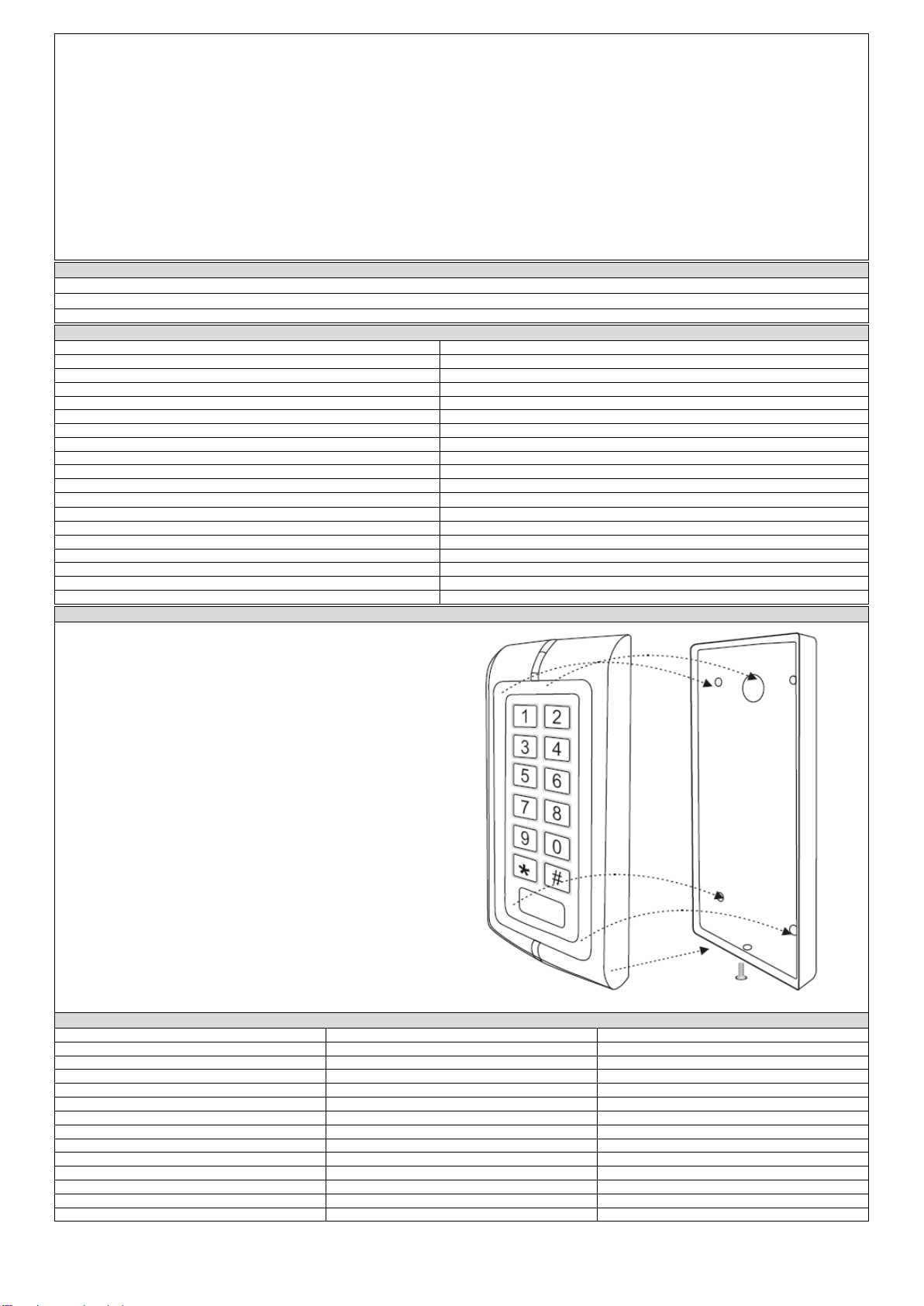
Zamek szyfrowy OR-ZS-804 jest wielofunkcyjnym i autonomicznym systemem z klawiaturą kontroli dostępu oraz czytnikiem kart i breloków zbliżeniowych. Może
pracować samodzielnie, a także jako część bardziej rozbudowanego systemu (z urządzeniami takimi jak domofony, wideodomofony, systemy alarmowe) przeznaczonym
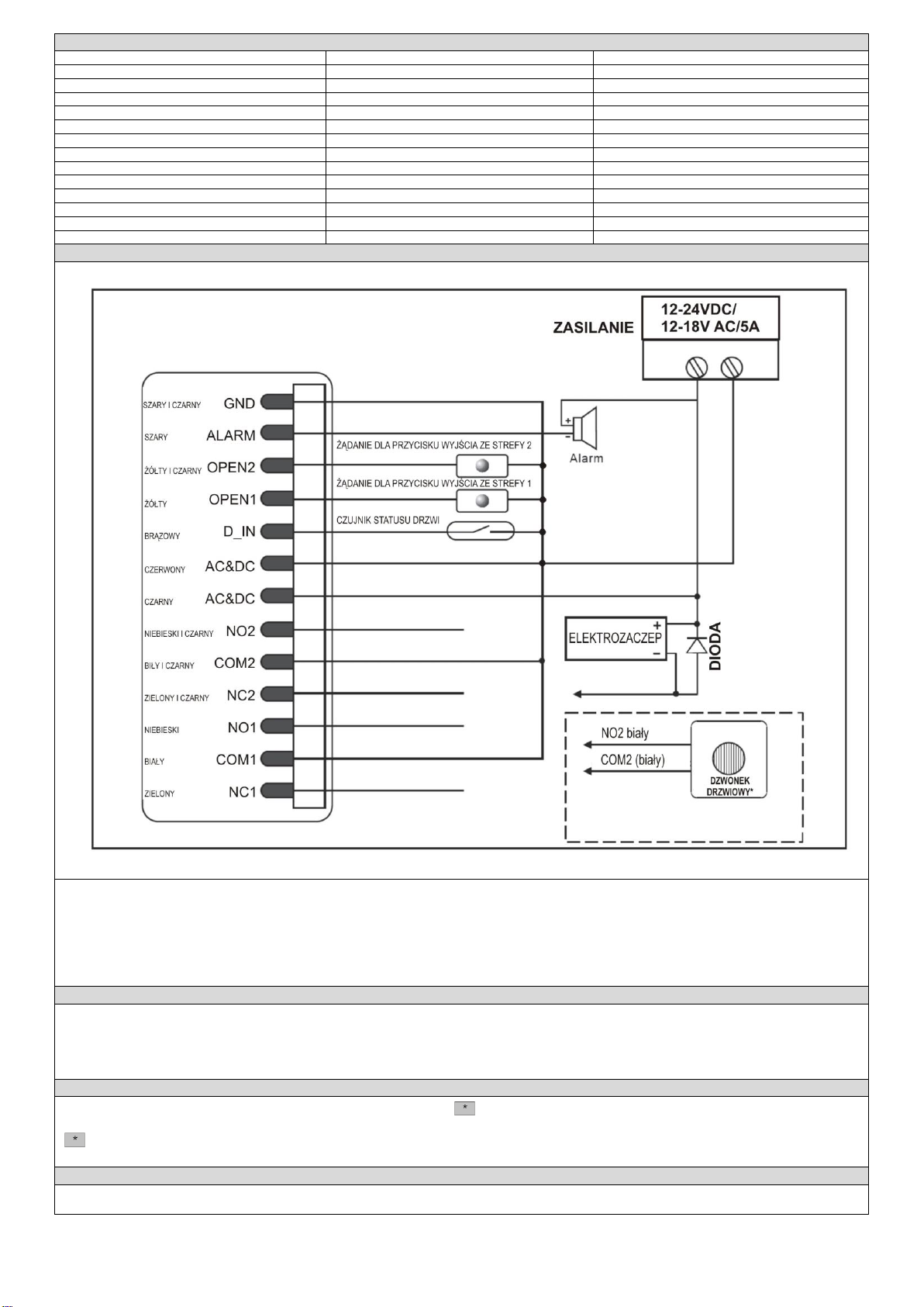
do wykorzystania w systemach bezpieczeństwa. Urządzenie posiada 2 wyjścia przekaźnikowe, które mogą sterować 2 oddzielnymi wejściami.
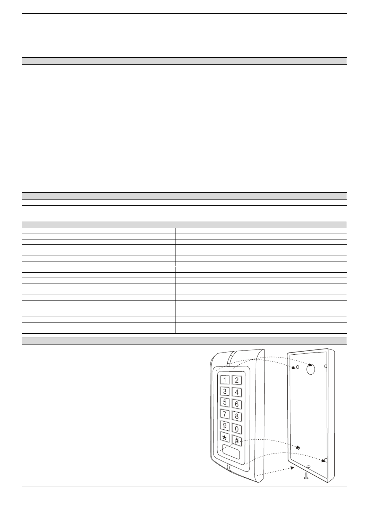
Zamek szyfrowy mieści się w mocnej, wodoszczelnej (IP68) i wandaloodpornej obudowie z nakładanym elektrolitycznie stopem cynku. Urządzenie może być
zamontowane w dowolnym miejscu, zarówno wewnątrz jak i na zewnątrz.

2
System może obsługiwać maksymalnie 1200 użytkowników za pomocą kodów PIN lub przy wykorzystaniu karty zbliżeniowej (w pierwszej strefie do 1100
użytkowników, w drugiej strefie do 100 użytkowników). Wbudowany czytnik kart obsługuje karty i breloki zbliżeniowe działające na częstotliwości 125 kHz EM oraz
kody PIN o długości od 4 do 6 cyfr.
Oba przekaźniki zamontowane w urządzeniu mogą pracować w trybie impulsowym (przydatnym do kontroli dostępu) lub w trybie bistabilnym (przydatnym do
uzbrajania/rozbrajania alarmów, włączania świateł, maszyn, itp.).
Zamek szyfrowy OR-ZS-804 posiada wiele dodatkowych funkcji, w tym rejestracja kart i podświetlenie klawiatury. Jest on idealnym urządzeniem do małych sklepów
i domów mieszkalnych, a także znajduje zastosowanie w handlu i przemyśle – w fabrykach, magazynach, laboratoriach, bankach.
CHARAKTERYSTYKA
•2 wyjścia przekaźnikowe, które mogą sterować dwoma oddzielnymi wejściami
•czytnik kart zbliżeniowych ID
•obsługa za pomocą kodów PIN i kart zbliżeniowych
•obsługa do 1200 użytkowników
•3 tryby sterowania wejściem: karta, PIN, karta+PIN
•długość kodu PIN: 4 - 6 cyfr
•częstotliwość czytnika kart: 125 kHz
•kod PIN zabezpieczony 100 milionami możliwych kombinacji
•pojemność pamięci: w strefie 1 do 1100 posiadaczy PIN lub kart, w strefie 2 do 100 posiadaczy PIN lub kart
•tryb impulsowy (po aktywacji wyjścia przesyłany jest impuls o zdefiniowanej długości), tryb bistabilny (po aktywacji wyjście jest załączone do momentu ponownej
jego aktywacji)
•rejestracja kart (1100 kolejnych kart w ciągu 1 minuty)
•podświetlana klawiatura
•obudowa wandaloodporna z nakładanym elektrolitycznie stopem cynku
•stopień ochrony obudowy: IP68
•wbudowany fotorezystor (LDR) do zabezpieczania przed dostępem osób niepowołanych
•regulacja czasu działania przekaźnika, czasu działania alarmu, czasu otwarcia drzwi
•trzy wskaźniki diodowe (czerwona, żółta i zielona)
•możliwość podłączenia dzwonka przewodowego (2 strefa)
•zasilanie: 12-24VDC/12-18VAC
SKŁAD ZESTAWU
Klawiatura numeryczna x 1
Instrukcja obsługi x 1
Zestaw wkrętów do mocowania x 1
SPECYFIKACJA TECHNICZNA
Napięcie zasilania:
12-24VDC/12-18VAC
Liczba użytkowników:
1200
Częstotliwość czynnika:
125 kHz
Klawiatura:
12 klawiszy; 2 x 6 cyfr
Typ karty:
ID
Odległość odczytu karty:
3-6 cm
Długość kodu PIN:
4-8 cyfr
Pobór prądu w stanie spoczynku:
25 +/- 5 mA
Pobór prądu podczas pracy:
<60 mA
Obciążalność wyjść przekaźnikowych:
2A
Obciążenia wyjścia alarmu:
20A
Dopuszczalna temperatura:
-25℃~60℃
Stopień ochrony:
IP68
Regulacja czasu aktywacji wyjścia przekaźnikowego (elektrozaczep):
1-99 sekund
Regulacja czasu aktywacji alarmu:
0-3 minut
Podłączenia elektryczne:
Przycisk blokowania wyjścia, DOTL, alarm zewnętrzny
Możliwe metody kontroli dostępu:
karta zbliżeniowa, kod+karta, kod lub karta
Wymiary:
58 x 135 x 26 mm
Waga netto:
0,65kg
MONTAŻ
1. Zdjąć tylną pokrywę klawiatury.
2. Wywiercić cztery otwory w ścianie (na śruby) i jeden otwór na przewód.
3. Zamocuj starannie tylną pokrywę na ścianie przy pomocy 4 wkrętów montażowych.
4. Przeprowadzić przewód przez otwór w ścianie.
5. Przy pomocy gumowych zaślepek uszczelnić otwory na śruby.
6. Zamocować klawiaturę do tylnej pokrywy.
Rys.1

3
INSTALACJA
Kolor
Funkcja
Opis
Szary i czarny
MASA
Biegun ujemny
Szary
Alarm -
Przewód ujemny alarmu
Żółty i czarny
OPEN2
Żądanie dla przycisku wyjścia w strefie 2
Żółty
OPEN1
Żądanie dla przycisku wyjścia w strefie 1
Brązowy
D_IN
Wykrywanie statusu drzwi
Czerwony
AC i DC
Wejścia zasilania 12-24VDC/12-18VAC
Czarny
AC i DC
Wejścia zasilania 12-24VDC/12-18VAC
Niebieski i czarny
NO2
Styk normalnie otwarty wyjścia przekaźnikowego 2
Biały i czarny
COM2
Styk wspólny wyjścia przekaźnikowego 2
Zielony i czarny
NC2
Styk normalnie zamknięty wyjścia przekaźnikowego 2
Niebieski
NO1
Styk normalnie otwarty wyjścia przekaźnikowego 1
Biały
COM1
Styk wspólny wyjścia przekaźnikowego 1
Zielony
NC1
Styk normalnie zamknięty wyjścia przekaźnikowego 1
SCHEMAT PODŁĄCZENIA
* Instalowanie i użytkowanie dzwonka drzwiowego. Podłączyć dzwonek drzwiowy przy użyciu przewodów NO2 i COM2. Nacisnąć #, zamek wyśle sygnał do dzwonka.
Uwagi:
W strefie 2 istnieje możliwość podłączeni dzwonka, jeżeli nie ma potrzeby uruchamiania drugich drzwi. Podłączenie dzwonka drzwiowego należy przeprowadzić
przewodami NO2 i COM2.
Wciśniecie przycisku # na klawiaturze spowoduje, że zamek wyśle sygnał włączenia do dzwonka drzwiowego. Dzwonek przestanie działać po zwolnieniu przycisku „#”.
Podłączyć biegun ujemny blokady do NC /normalnie zamknięty/, jest to blokada odporna na uszkodzenia.
Podłączyć biegun ujemny blokady do NO /normalnie otwarty/, jest to blokada działająca w przypadku zaniku zasilania.
DZIAŁANIE PRZEKAŹNIKOWE (tryb impulsowy i bistabilny)
Oba przekaźniki umieszczone na płytce mogą pracować w trybie impulsowym (przydatne do sterowania dostępem) lub bistabilnym (przydatne do uzbrajania/
rozbrajania alarmów, załączania oświetlenia, maszyn, itp.).
Za każdym razem po użyciu ważnej karty lub wpisaniu kodu PIN w trybie impulsowym przekaźnik będzie działać przez uprzednio nastawiony czas impulsu.
Za każdym razem po użyciu ważnej karty lub wpisaniu kodu PIN w trybie bistabilnym, przekaźnik zmieni swój stan, i pozostanie w nim aż do kolejnego użycia karty lub
kodu PIN.
PRZYWRACANIE USTAWIEŃ FABRYCZNYCH
W celu przywrócenia ustawień fabrycznych należy wyłączyć zasilanie, nacisnąć , przytrzymać i włączyć zasilanie. Przytrzymać przycisk aż do usłyszenia trzech
sygnałów (dwa krótkie, jeden długi). Oznacza to, że ustawienia fabryczne zostały pomyślnie przywrócone. Długi sygnał dźwiękowy pojawi się po zwolnieniu przycisku
.
Uwaga: przywrócenie ustawień fabrycznych nie powoduje utraty informacji użytkownika.
ANTYSABOTAŻ
Jako alarm próby manipulacji wywołany przez niepowołane osoby wykorzystano w OR-ZS-804 fotorezystor. Jeżeli klawiatura zostanie usunięta z pokrywy, włączy się
sygnał alarmu.

4
SYGNALIZACJA DŹWIĘKOWA I OPTYCZNA
Status działania
Światło czerwone
Światło zielone
Światło niebieskie
Brzęczyk
Strefa 1, odblokowana
-
Jasne
-
Krótki dzwonek
Strefa 2, odblokowana
-
-
Jasne
Krótki dzwonek
Zasilanie
Jasne
-
-
Długi dzwonek
Gotowość
Zapala się powoli
-
-
-
Naciśnięcie klawisza
-
-
-
Krótki dzwonek
Operacja zakończona
pomyślnie
-
-
Jasny
Długi dzwonek
Operacja zakończona
niepowodzeniem
-
-
-
3 krótkie dzwonki
Wprowadzenie trybu
programowania
Jasny
-
-
Długi dzwonek
Wprowadzony tryb
programowania
Jasny
Jasny
-
-
Wyjście z trybu
programowania
Zapala się powoli
-
-
Długi dzwonek
Alarm
Zapala się szybko
-
-
Alarm
Tryb programowania - instrukcja
1. Ustawienia administratora
Wejście w tryb programowania
0 Master code # (*, MASTER kod, #)
Fabrycznie ustawiony kod MASTER to: 888888
Wyjście z trybu programowania
*
Uwaga: wszystkie kroki opisane poniżej muszą być wykonywane po wprowadzeniu trybu programowania
Zmiana kodu master
0 New code # New code #
(0, nowy kod, # nowy kod, #)
Kod MASTER zawiera 6 dowolnych cyfr.
Ustawianie trybu działania:
Wprowadzanie użytkowników ważnych kart lub kodów PIN
3 1 2 # Zone 1 (3, 1, 2, # - strefa 1)
3 2 2 # Zone 2 (3, 2, 2, # - strefa 2)
Wejście przez użycie albo karty albo kodu PIN (ustawienie fabryczne).
Wprowadzanie użytkowników ważnych kart i kodów PIN
3 1 1 # Zone 1 (3, 1, 1, # - strefa 1)
3 2 1 # Zone 2 (3, 2, 1, # - strefa 2)
Wejście przez użycie razem karty i kodu PIN.
Uwaga: Jeżeli użytkownik karty lub kodu PIN jest już zarejestrowany, nie można dodać go ponownie w tej samej strefie. Przy próbie wprowadzania rozlegnie się
dzwonek, sygnalizujący błąd.
Ustawienia fabryczne: tryb karty lub kodu PIN
Wprowadzanie użytkownika do strefy 1: (3 1 2 # )
Dodawanie użytkowników kodu PIN
1 User ID number # PIN #
(1, numer identyfikacyjny użytkownika, #, PIN, #)
Numery identyfikacyjne to dowolne liczby z zakresu 1 ~ 1100. PIN to kod zawierający 4~6 cyfr
z zakresu 0000 ~ 99999999, z wyjątkiem 1234, który to numer jest zastrzeżony. Użytkownicy
mogą być dodawani kolejno, bez potrzeby wychodzenia z trybu programowania, w sposób
następujący:
1 User ID No 1 # PIN # User ID No 2 # PIN #
(1, numer identyfikacyjny (ID) użytkownika 1, #, PIN, #, ID użytkownika 2, #, PIN, #)
Kasowanie kodu PIN użytkownika
2 User ID number # (2, ID użytkownika, #)
Użytkownicy mogą być usuwani kolejno, bez potrzeby wychodzenia z trybu programowania
Zmiana kodu PIN lub użytkownika kodu PIN
(Uwaga: ten krok musi być wykonany poza trybem
programowania)
* ID Number # Old PIN # New PIN # New PIN #
(*, ID#, stary PIN#, Nowy PIN#, Nowy PIN#)
Dodawanie użytkownika karty: (metoda 1)
Jest to łatwy sposób wprowadzania kart z automatycznie
generowanymi numerami identyfikacyjnymi. Jeżeli poprzednio nie
został wprowadzony żaden numer identyfikacyjny, numer ten
zaczynie się od 1.
1 Read card # (1, odczyt karty, #)
Karty mogą być dodawane bez potrzeby wychodzenia z trybu programowania.
Dodawanie użytkownika karty (metoda 2)
Jest to alternatywny sposób wprowadzania kart z
wykorzystaniem przydziału numeru identyfikacyjnego
użytkownika. W tej metodzie numer użytkownika jest
przypisywany do karty. Do jednej karty może zostać przypisany
tylko jeden użytkownik.
1 ID Number # Read card #
(1, numer identyfikacyjny, #, karta, #)
Numer identyfikacyjny to dowolna liczba z zakresu 1 –1100
Dodawanie serii kart –rejestrowanie blokowe
Numery kart muszą być kolejne (operacja możliwa tylko dla strefy
1)
5 ID Number # 8 dig Card number # Card quantity #
(5, numer identyfikacyjny, #, ośmiocyfrowy numer karty, #, ilość kart, #)
Ilość kart – od 1 do 1100.
Ośmiocyfrowy numer karty to 8 ostatnich cyfr na karcie.
Można zarejestrować 1100 kart w ciągu 1 minuty.
Kasowanie użytkowników kart przy pomocy kart.
Uwaga: użytkownicy mogą być usuwani kolejno, bez potrzeby
wychodzenia z trybu programowania
2 Read card # (2, odczyt karty, #)
Urządzenie może automatycznie zidentyfikować karty ze strefy 1 lub strefy 2.
Szczegółowa instrukcja programowania
Wejście w tryb programowania
0 Master code # (*, MASTER kod, #)
Fabrycznie ustawiony kod MASTER to: 888888
Wyjście z trybu programowania
*
Proszę zwrócić uwagę, że opisane poniżej programowanie musi odbywać się przy zalogowanym nadrzędnym użytkowniku

5
Zmiana kodu master
0 New code # New code #
(0, nowy kod, # nowy kod, #)
Kod MASTER zawiera 6 dowolnych cyfr.
Dodawanie kodu PIN użytkownika dla strefy 1
Dodawanie kodu PIN użytkownika dla strefy 2
1 User ID number (1-1100) # PIN #
(1, numer identyfikacyjny użytkownika (1 – 1100), #, PIN, #)
1 User ID number (1101-1200) # PIN #
(1, numer identyfikacyjny użytkownika (1101 – 1200), #, PIN, #)
Numer użytkownika to jakakolwiek liczba z zakresu 1 do 1100 dla strefy 1 i jakakolwiek liczba z
zakresu 1101 do 1200 dla strefy 2.
Kod PIN to dowolna 4 –6 cyfrowa liczba z zakresu od 0000 do 99999999 z wyjątkiem 1234 (ta
liczba jest zarezerwowana).
Użytkownicy mogą być dodawani kolejno, bez konieczności wychodzenia z trybu programowania.
Dodawanie użytkownika karty dla strefy 1
Dodawanie użytkownika karty dla strefy 2
1 Read card # (1, odczyt karty, #)
5 Read card # (5, odczyt karty, #)
Karty mogą być dodawane kolejno, bez konieczności wychodzenia z trybu programowania.
Kasowanie użytkownika kodu PIN lub użytkownika karty
2 User ID number #
(2, numer identyfikacyjny użytkownika, #) - dla użytkownika kodu PIN, lub
2 Read card # (2, odczyt karty, #) - dla użytkownika kodu PIN
Użytkownicy mogą być usuwani kolejno, bez konieczności wychodzenia z trybu programowania.
Odblokowanie drzwi dla strefy 1 lub strefy 2
Odblokowanie drzwi dla użytkownika kodu PIN
Wprowadzić kod PIN a następnie nacisnąć # .
Odblokowanie drzwi dla użytkownika karty.
Zbliżyć kartę.
Kasowanie karty użytkowników przy pomocy numeru
identyfikacyjnego. Ta opcja może zostać wykorzystana, jeżeli
użytkownik zgubił swoją kartę.
2 User ID #
(2, numer identyfikacyjny użytkownika, #)
Kasowanie karty użytkowników przy użyciu numeru karty.
9 Input 8 digits card number #
(9, 8-cyfrowy numer karty, #)
Karty mogą być kasowane kolejno, bez konieczności wychodzenia z trybu programowania.
Ustalanie użytkownika dla strefy 2 (3 2 2 #)
Ustalanie kodu PIN użytkownika dla strefy 2 dokonywane jest w taki sam sposób jak dla strefy 1, jedynie numer identyfikacyjny mieści się w zakresie 1101 do 1200.
Ustalanie karty użytkownika dla strefy 2 dokonywane jest w taki sam sposób jak dla strefy 1, jedynie dodawanie kart użytkowników z automatycznie generowanymi
numerami identyfikacyjnymi (metoda 1) dokonywane jest w poniższy sposób:
Dodawanie kart użytkowników (metoda 1).
Automatyczne generowanie numerów identyfikacyjnych.
5 Read card # (5, odczyt karty, #)
Karty mogą być kasowane kolejno, bez konieczności wychodzenia z trybu programowania.
Tryb kart i kodu PIN
Ustalanie użytkownika dla strefy 1 (3 1 1 #)
Dodawanie użytkownika karty i kodu PIN.
(Kod PIN to dowolna 4 –8 cyfrowa liczba z zakresu 0000 do
99999999, z wyjątkiem 1234 –ta liczba jest zastrzeżona).
Dodać kartę jak dla użytkownika kart.
W celu wyjścia z trybu programowania należy nacisnąć * , a następnie przydzielić kod PIN w
następujący sposób:
* Read Card 1234 # PIN # PIN #
(*, odczyt karty, 1234 #, PIN #, PIN #)
W celu zmiany kodu PIN w trybie karty i kodu PIN (metoda 1) –
należy zwrócić uwagę na fakt, że jest to wykonywane poza
trybem programowania, tak że użytkownik może to wykonać
samodzielnie.
* Read Card # Old PIN # New PIN # New PIN #
(*, odczyt karty, stary PIN #, nowy PIN #, nowy PIN #)
W celu zmiany kodu PIN w trybie karty i kodu PIN (metoda 2) –
należy zwrócić uwagę na fakt, że jest to wykonywane poza
trybem programowania, tak że użytkownik może to wykonać
samodzielnie.
* ID Number # Old PIN # New PIN # New PIN #
(*, numer identyfikacyjny #, stary PIN#, Nowy PIN#, Nowy PIN#)
W celu skasowania użytkownika karty i kodu PIN należy po
prostu skasować kartę
2 Read card # lub 2 User ID #
(2, odczyt karty, # lub 2, numer identyfikacyjny użytkownika, #)
Ustalanie użytkownika dla strefy 2 (3 1 2 #) wykonywane jest tak samo jak dla strefy 1.
Tylko tryb karty (w tym trybie użytkownicy mogą zostać wprowadzeni przy pomocy karty)
Tylko dla ustalania użytkownika karty
3 1 0 # Zone 1 (3, 1, 0, # - strefa 1)
3 2 0 # Zone 2 (3, 2, 0, # - strefa 2)
Wejście tylko przy pomocy karty.
Kasowanie wszystkich użytkowników
Kasowanie wszystkich użytkowników. Uwaga: ta funkcja jest
nieodwracalna. Zastanów się zanim ją wykonasz.
Kasowanie wszystkich użytkowników strefy 1:
2 0000 #
Kasowanie wszystkich użytkowników strefy 2:
9 0000 #

6
Odblokowanie drzwi (lub zmiana statusu przekaźnika)
Dla użytkownika kodu PIN
Wprowadzić PIN , a następnie nacisnąć #
Dla użytkownika karty
Read card (odczyt karty)
Dla użytkowników karty i kodu PIN
Read card (odczyt karty), a następnie wprowadzenie PIN #
Skrócona instrukcja programowania
Ustawienie przekaźnika (tryb impulsowy, tryb bistabilny)
Tryb impulsowy - ustawienie czasu przekaźnika drzwi
Dla strefy 1: 4 1 1~99 #
Dla strefy 2: 4 2 1~99 #
Czas przekaźnika drzwi mieści się w zakresie od 1 do 99 sekund, ustawienie fabryczne to 5
sekund, 1 oznacza strefę 1, 2 oznacza strefę 2.
Tryb bistabilny
Dla strefy 1: 4 1 0 #
Dla strefy 2: 4 2 0 #
Czujnik otwarcia drzwi, alarm, sygnał dźwiękowy, ustawienie dzwonka drzwi
Wykrywanie otwarcia drzwi
Jeżeli używany jest opcjonalny styk magnetyczny lub jest wbudowany magnetyczny styk zamka, drzwi są otwierane normalnie. Jeżeli drzwi nie zostaną zamknięte po upływie 1
minuty, automatycznie włącza się sygnał dźwiękowy, przypominający o konieczności zamknięcia drzwi. Będzie on działać przez 1 minutę przed automatycznym wyłączeniem.
ANTYSABOTAŻ. Jeżeli używany jest opcjonalny styk magnetyczny lub jest wbudowany magnetyczny styk zamka a drzwi zostaną otwarte przy użyciu siły lub jeżeli drzwi zostaną
otwarte po upływie 20 sekund po niewłaściwym zamknięciu elektrozaczepu, włączy się zarówno wewnętrzny brzęczyk jak i sygnał alarmowy.
Wyłączanie wykrywania otwarcia drzwi (ustawienie fabryczne)
6 0 #
Włączanie wykrywania drzwi
Dla strefy 1: 6 1 #
Dla strefy 2: 6 2 #
Można uaktywnić wykrywanie otwarcia drzwi tylko dla jednej strefy.
Opcja blokowania klawiatury i wyjście alarmu: jeżeli zostanie wykrytych 10 nieważnych kart lub 10 niewłaściwych kodów PIN w okresie 10-minutowym, klawiatura zostanie
zablokowana na 10 minut lub uruchomi się na 10 minut alarm, zależnie od opcji wybranej poniżej.
Stan normalny: bez blokowania klawiatury lub włączania alarmu
7 0 # ustawienie fabryczne
Blokada klawiatury
7 1 #
Włączanie alarmu
7 2 #
Czas działania alarmu
Ustawienie czasu działania alarmu (1 – 3 minuty. Ustawienie
fabryczne to 1 minuta)
8 1~3 #
Sygnał akustyczny
Istnieje możliwość włączenia lub wyłączenia sygnału akustycznego. Po włączeniu, urządzenie będzie wydawać dźwięki przy naciskaniu klawiszy, po wyłączeniu dźwięki
takie nie będą wydawane.
Stan normalny: włączone
8 6 # ustawienie fabryczne
Sygnał akustyczny wyłączony
8 7 #
Zmiana strefy 2 na dzwonek drzwiowy
(Jeżeli nie ma potrzeby obsługiwania drugich drzwi, strefa 2 może być ustawiona jako dzwonek. Dzwonek drzwiowy powinien zostać przyłączony do COM2 i NO2.
Naciśnięcie klawisza „#” na klawiaturze spowoduje wysłanie sygnału do dzwonka drzwiowego.
Strefa 2
8 8 # ustawienie fabryczne
Dzwonek drzwiowy
8 9 #
Kasowanie alarmu
W celu skasowania ostrzeżenia po siłowym otwarciu drzwi
należy:
Read valid card or Master Code #
(Odczyt ważnej karty lub kod nadrzędny #)
W celu skasowania ostrzeżenia o zbyt długim otwarciu drzwi
Zamknąć drzwi lub Read valid card (odczyt ważnej karty) lub Master Code # (kod MASTER #)
EN
Operation Instruction
DESCRIPTION AND USE
OR-ZS-804 code lock is a multifunctional and autonomous system with an access control keypad and a proximity card and tag reader. It can work independently, as
well as part of a more complex system (with devices such as intercoms, video intercoms, alarm systems). It is designed for use in security systems. The device has 2
relay outputs that can control 2 separate inputs.
The code lock is housed in a robust, waterproof (IP68) and vandal-proof zinc alloy electropolished case. The device can be mounted anywhere, both indoors and
outdoors.
The system can support up to 1,200 users via PIN codes or a proximity card (up to 1,100 users in the first zone, up to 100 users in the second zone). The built-in card
reader supports proximity cards and tags operating at a frequency of 125 kHz EM and PIN codes with a length of 4 to 6 digits.
Both relays fitted to the device can operate in pulse mode (useful for access control) or in bistable mode (useful for arming/disarming alarms, turning on lights,
machinery, etc).
Code lock OR-ZS-804 has many additional features, including card registration and keypad backlighting. It is an ideal device for small shops and residential houses, as
well as for use in trade and industry - in factories, warehouses, laboratories, banks.
CHARACTERISTICS
•2 relay outputs that can control two separate inputs
•ID proximity card reader
•PIN and proximity card operation
•up to 1,200 users
•3 entry control modes: card, PIN, card+PIN
•PIN code length: 4 - 6 digits

7
•Card reader frequency: 125 kHz
•PIN code protected by 100 million possible combinations
•Memory capacity: Zone 1 to 1100 PIN or cardholders, Zone 2 to 100 PIN or cardholders
•impulse mode (upon activation of the output, a pulse of a defined length is transmitted), bistable mode (upon activation, the output is switched on until it is activated
again)
•card registration (1100 consecutive cards in 1 minute)
•backlit keypad
•vandal-proof housing with electrolytically applied zinc alloy
•ingress protection: IP68
•built-in photoresistor (LDR) for protection against unwanted access
•adjustment of relay action time, alarm action time, door opening time
•three LED indicators (red, yellow and green)
•possibility to connect a wired doorbell (2 zone)
•power supply: 12-24VDC/12-18VAC
ELEMENTS OF THE SET
Numeric keypad x 1
Operating instructions x 1
Set of fixing screws x 1
TECHNICAL SPECIFICATION
Power supply voltage:
12-24VDC/12-18VAC
User capacity:
1200
Reader frequency:
125 kHz
Keypad:
12 keys; 2 x 6 digits
Card type:
ID
Card reading distance:
3-6 cm
PIN code length:
4-8 digits
Current consumption at standby:
25mA +/- 5mA
Current consumption at work:
<60mA
Relay outputs load capacity:
2A
Alarm output load:
20A
Operating temperature:
-25℃~60℃
Ingress protection:
IP44
Adjustable door relay time:
1-99 seconds
Adjustable alarm time:
0-3 minutes
Electrical connections:
Output lock button, DOTL, external alarm
Access modes:
Proximity card, PIN code + proximity card, PIN code or proximity card
Dimensions:
58 x 135 x 26mm
Net weight:
0.65kg
INSTALLATION
1. Remove the back cover of the keypad.
2. Drill four holes in the wall (for screws) and one hole for the cable.
3. Fix the back cover carefully on the wall using 4 mounting screws.
4. Pass the cable through the hole in the wall.
5. Use rubber plugs to seal the screw holes.
6. Attach the keypad to the back cover.
INSTALLATION
Color
Function
Description
Grey and black
MASA
Negative pole
Grey
Alarm -
Negative alarm cable
Yellow and black
OPEN2
Request for exit button in zone 2
Yellow
OPEN1
Request for exit button in zone 1
Brown
D_IN
Door status detection
Red
AC i DC
12-24VDC/12-18VAC power inputs
Black
AC i DC
12-24VDC/12-18VAC power inputs
Blue and black
NO2
Normally open contact of relay output 2
White and black
COM2
Common contact for relay output 2
Green and black
NC2
Normally-closed contact of relay output 2
Blue
NO1
Normally open contact of relay output 1
White
COM1
Common contact for relay output 1
Green
NC1
Normally-closed contact of relay output 1

8
WIRING DIAGRAM
•* Installing and using the doorbell. Connect the doorbell using leads NO2 and COM2. Press #, the lock will send a signal to the doorbell.
Notes:
In zone 2 it is possible to connect a doorbell if it is not necessary to operate the second door. The doorbell is connected via the NO2 and COM2 wires.
Pressing the # button on the keypad will cause the lock to send an activation signal to the doorbell. The doorbell will stop working when the "#" button is released.
Connect the negative pole of the lock to NC /normally closed/, this is a fail-safe lock.
Connect the negative pole of the lock to NO /normally open/, this is the lock that operates in the event of a power failure.
RELAY OPERATION (pulse and bistable mode)
Both relays on the board can operate in pulse mode (useful for access control) or bistable mode (useful for arming/disarming alarms, switching on lights, machines, etc.).
Each time a valid card is used or a PIN is entered in pulse mode, the relay will operate for a pre-set pulse time.
Each time a valid card is used or a PIN is entered in bistable mode, the relay will change its state, and remain in that state until the next time the card or PIN is used.
RESTORE FACTORY SETTINGS
To restore the factory settings, switch off the power, press and hold , switch on the power. Hold the button down until you hear three beeps (two short, one long).
This means that the factory settings have been successfully restored. A long beep will sound when the button is released .
Important: restoring the factory settings does not result in the loss of user information.
ANTI-SABOTAGE
As a tampering alarm the OR-ZS-804 uses a photoresistor. If the keypad is removed from its cover, the alarm signal is activated.
AUDIBLE AND OPTICAL SIGNALLING
Operating status
Red diode
Green diode
Blue diode
Buzzer
Zone 1, unlocked
-
Bright
-
Short call
Zone 2, unlocked
-
-
Bright
Short call
Power
Bright
-
-
Long call
Readiness
Lights up slowly
-
-
-
Pressing the button
-
-
-
Short call
Operation successful
-
-
Bright
Long call
Operation failed
-
-
-
3x Short call
Entering programming mode
Bright
-
-
Long call
Entered programming mode
Bright
Bright
-
-
Exit programming mode
Lights up slowly
-
-
Long call
Alarm
Lights up quickly
-
-
Alarm
Programming mode - instruction
1. administrator settings
To enter the programming mode
0 Master code #
The factory set MASTER code is: 888888
To exit from the programming mode
*
Important: all steps described below must be performed after entering the programming mode
Change of master code
0 New code # New code #
The MASTER code contains any 6 digits

9
Setting the operation mode:
User input of a valid card or PIN
3 1 2 # Zone 1
3 2 2 # Zone 2
Entry via either card or PIN (factory setting).
User input of valid cards and PINs
3 1 1 # Zone 1
3 2 1 # Zone 2
Entry via the use of card and PIN together.
Note: If a card or PIN user is already registered, they cannot be added again in the same zone. A bell will sound when attempting to enter, indicating an error.
Factory settings: Card or PIN mode
Entering user in zone 1: (3 1 2 # )
Adding PIN code users
1 User ID number # PIN #
Identification numbers are any numbers in the range 1 ~ 1100. PIN is a code containing 4~6 digits
in the range in the range 0000 ~ 99999999, except 1234, which is a restricted number. Users can
be added sequentially without exiting programming mode as follows:
1 User ID No 1 # PIN # User ID No 2 # PIN #
Deleting PINcode of the user
2 User ID number #
Users can be deleted one by one without having to exit programming mode
Change of PIN code or PIN code user
(Note: this step must be performed outside the programming
mode)
* ID Number # Old PIN # New PIN # New PIN #
Adding a card user: (method 1)
This is an easy way to enter cards with automatically generated
ID numbers. If no ID number has been entered previously, the
number will start with 1.
1 Read card #
Cards can be added without exiting programming mode.
Adding a card user: (method 2)
This is an alternative method of card entry using the assignment
of a user ID number. In this method, a user number is assigned to
a card. Only one user can be assigned to a single card.
1 ID Number # Read card #
The identification number is any number between 1 and 1100
Adding card series - block recording
Card numbers must be consecutive (operation possible only for
zone 1)
5 ID Number # 8 dig Card number # Card quantity #
Number of cards - from 1 to 1100.
The 8-digit card number is the last 8 digits on the card.
You can register 1100 cards in 1 minute.
Deleting card users with cards
Note: users can be deleted consecutively without having to exit
the programming mode
2 Read card #
The device can automatically identify cards from zone 1 or zone 2.
Detailed programming instructions
To enter the programming mode
0 Master code #
The factory set MASTER code is: 888888
To exit from the programming mode
*
Please note that the programming described below must be carried out with the master user logged in
Change of master code
0 New code # New code #
The MASTER code contains any 6 digits
Adding user PIN for zone 1
Adding user PIN for zone 2
1 User ID number (1-1100) # PIN #
1 User ID number (1101-1200) # PIN #
The user number is any number in the range 1 to 1100 for zone 1 and any
number in the range 1101 to 1200 for zone 2.
The PIN code is any 4 - 6 digit number from 0000 to 99999999 except 1234 (this
number is reserved).
Users can be added sequentially without exiting programming mode.
Adding a card user for zone 1
Adding a card user for zone 2
1 Read card #
5 Read card #
Cards can be added sequentially without exiting programming mode.
Deleting PIN code user or card user
2 User ID number # - for the PIN code user, or
2 Read card # - for card user
Users can be deleted sequentially without having to exit programming mode.
Unlock the door for zone 1 or zone 2
Unlocking the door for PIN code users
Enter PIN code and next press # .
Unlocking the door for the cardholder
Read card
Deletion of the users card by means of an identification number. This option can
be used if a user has lost their card.
2 User ID #
Deleting the user card using the card number
9 Input 8 digits card number #
Cards can be deleted sequentially without exiting programming mode.
Entering user in zone 2 (3 2 2 #)
Determining the user PIN for zone 2 is done in the same way as for zone 1, only the ID number is in the range 1101 to 1200. Determining the user card for zone 2 is
done in the same way as for zone 1, only adding user cards with automatically generated ID numbers (method 1) is done as follows:
Adding user cards (method 1).
Automatic generation of identification numbers.
5 Read card #
Cards can be deleted sequentially without exiting programming mode.
Card and PIN code mode

10
Entering user in zone 1 (3 1 1 #)
Adding a card user and PIN.
(PIN code is any 4 - 8 digit number from 0000 to 99999999,
except 1234 - this number is restricted).
Add a card as for the card user.
In order to leave the programming mode, press * , and then assign the PIN code as follows:
* Read Card 1234 # PIN # PIN #
To change the PIN code in card and PIN code mode (method 1) -
note that this is done outside of programming mode so that the
user can do it themselves.
* Read Card # Old PIN # New PIN # New PIN #
To change the PIN code in card and PIN code mode (method 2) -
note that this is done outside of programming mode so that the
user can do it themselves.
* ID Number # Old PIN # New PIN # New PIN #
To delete a card user and PIN code, simply delete the card
2 Read card # or 2 User ID #
Entering user in zone 2 (3 1 2 #) is performed in the same way as for zone 1.
Card mode only (in this mode users can be entered using a card)
Only for the establishment of the card user
3 1 0 # Zone 1
3 2 0 # Zone 2
Entry by card only.
Deleting all users
Delete all users. Note: this function is irreversible. Please think
twice before performing it.
Deleting all zone 1 users:
2 0000 #
Deleting all zone 2 users:
9 0000 #
Unlocking the door (or changing the status of the relay)
For PIN code user
Enter PIN code , next press #
For card user
Read card
For card and PIN users
Read card , and next enter PIN code #
Quick programming guide
Relay setting (pulse mode, bistable mode)
Pulse mode - setting the door relay time
For zone 1: 4 1 1~99 #
For zone 2: 4 2 1~99 #
Door relay time ranges from 1 to 99 seconds, factory setting is 5 seconds, 1 indicates zone 1, 2
indicates zone 2.
Bistable mode
For zone 1: 4 1 0 #
For zone 2: 4 2 0 #
Door open detector, alarm, acoustic signal, door bell setting
Door opening detection
If the optional magnetic contact is used or a magnetic lock contact is built in, the door is opened normally. If the door is not closed after 1 minute, an audible signal is
automatically activated to remind you to close the door. It will operate for 1 minute before automatically switching off.
ANTI-SABOTAGE. If the optional magnetic contact is used or there is a built-in magnetic lock contact and the door is opened by force, or if the door is opened 20 seconds after
the electric door strike is closed incorrectly, both the internal buzzer and the alarm signal will sound.
Deactivating door opening detection (factory setting)
6 0 #
Activation of door detection
For zone 1: 6 1 #
For zone 2: 6 2 #
You can activate door opening detection for one zone only.
Keypad lock option and alarm output: if 10 invalid cards or 10 wrong PINs are detected in a 10-minute period, the keypad will be locked for 10 minutes or an alarm will be
triggered for 10 minutes, depending on the option selected below.
Normal state: without locking the keypad or activating the alarm
7 0 # factory setting
Keypad lock
7 1 #
Alarm activation
7 2 #
Alarm operating time
Alarm duration setting (1 - 3 minutes. Factory setting is 1 minute)
8 1~3 #
Acoustic signal
The acoustic signal can be switched on or off. When enabled, the device will beep when keys are pressed, when disabled it will not beep.
Normal state: On
8 6 # factory setting
Acoustic signal off
8 7 #

11
Change of zone 2 to doorbell
If there is no need to operate a second door, zone 2 can be set up as a doorbell. The doorbell should be connected to COM2 and NO2. Pressing the "#" key on the
keypad will send a signal to the doorbell.
Zone 2
8 8 # factory setting
Doorbell
8 9 #
Alarm reset
To cancel the warning after forcibly opening the door:
Read valid card or Master Code #
To cancel the warning for too long a door opening
Close door or Read valid card (read valid card) or Master Code #
DE
Bedienungsanleitung
BESCHREIBUNG
Das Zahlenschloss OR-ZS-804 ist ein multifunktionales und autonomes System mit einer Zugangskontrolltastatur und einem Karte- und RFID-Schlüsselanhängerleser.
Sie kann sowohl unabhängig als auch als Teil eines komplexeren Systems (mit Geräten wie Gegensprechanlagen, Videosprechanlagen, Alarmsystemen) benutzt werden.
Vorgesehen für den Einsatz in Sicherheitssystemen.
Das Gerät verfügt über 2 Relaisausgänge, die 2 separate Eingänge steuern können.
Das Zahlenschloss hat ein robustes, wasserdichtes (IP68) und vor Gewaltanwendung geschütztes Gehäuse aus elektropolierter Zinklegierung. Das Gerät kann überall
montiert werden, sowohl im Innen- als auch im Außenbereich.
Die beiden in das Gerät eingebauten Relais können im Impulsmodus (nützlich für die Zugangskontrolle) oder im bistabilen Modus (nützlich für die
Aktivierung/Deaktivierung von Alarmen, das Einschalten von Lichtern, Maschinen usw.) arbeiten.
CHARAKTERISTIK
•2 Relaisausgänge, die zwei separate Eingänge steuern können
•ID-Kartenleser
•Bedienung von PIN- und Transponderkarten
•Speichert bis zu 1200 User
•3 Eingangssteuerungsmodi: Karte, PIN, Karte+PIN
•Länge des PIN-Codes: 4 - 6 Ziffern
•Frequenz des Kartenlesers 125 kHz
•PIN-Code geschützt durch 100 Millionen mögliche Kombinationen
•Speicherkapazität: Zone 1 bis zu 1100 PIN- oder Karteninhaber, Zone 2 bis zu 100 PIN- oder Karteninhaber
•Impulsmodus (bei Aktivierung des Ausgangs wird ein Impuls einer bestimmten Länge gesendet), bistabiler Modus (bei Aktivierung wird der Ausgang bis zu seiner
nächsten Aktivierung eingeschaltet)
•Kartenregistrierung (1100 aufeinanderfolgende Karten innerhalb von 1 Minute)
•Beleuchtetes Tastenfeld
•Vor Gewaltanwendung geschütztes Gehäuse mit elektrolytisch aufgebrachter Zinklegierung
•Schutzart des Gehäuses: IP68
•eingebauter Fotowiderstand (LDR) zum Schutz vor unerwünschtem Zugriff
•Einstellung der Relaisaktionszeit, der Betriebszeit des Alarms, Türöffnungszeit
•drei Dioden-Anzeigen (rot, gelb und grün)
•Man kann eine Türklingel mit Kabel anschließen (2 Zonen)
•Spannungsversorgung: 12-24VDC/12-18VAC
ZUSAMMENSETZUNG DES BAUSATZES
Zifferntastatur x 1
Bedienungsanleitung x 1
Satz von Schaftschrauben x 1
TECHNISCHE DATEN
Versorgungsspannung:
12-24VDC/12-18VAC
Anzahl der Nutzer/innen:
1200
Frequenz des Lesers:
125 kHz
Tastatur:
12 Tasten; 2 x 6 Ziffern
Typ der Karte:
ID
Distanz der Ablesung der ID-Karte:
3-6 cm
Länge des PIN-Codes:
4-8 Ziffern
Stromverbrauch im Bereitschaftszustand:
<60mA
Stromverbrauch im Standby-Modus:
25 +/- 5mA
Belastbarkeit der Relaisausgänge:
2A
Ausgangslasten des Alarms:
20A
Betriebstemperatur:
-25℃~60℃
Schutzart:
IP68
Aktivierungszeit des Türrelais:
1-99 S (Einstellung)
Aktivierungszeit des Alarms:
0-3 Min
Elektrische Anschlüsse:
Ausgangssperrtaste, DOTL, externer Alarm
Mögliche Methoden der Zugangskontrolle:
Transponderkarte, Code+Karte, Code oder Karte
Abmessungen:
58 x 135 x 26 mm
Nettogewicht:
0,65kg

12
MONTAGE
1. Entfernen Sie die hintere Abdeckung des Tastenfelds.
2. Bohren Sie vier Löcher in die Wand (für Schrauben) und ein Loch für das Kabel.
3. Befestigen Sie die Rückwand des Geräts mit den 4 Befestigungsschrauben sorgfältig an
der Wand.
4. Führen Sie das Kabel durch das Loch in der Wand.
5. Verwenden Sie Blindstopfen zum Abdichten der Schraubenlöcher.
6. Bringen Sie das Tastenfeld an der hinteren Abdeckung an.
MONTAGE
Farbe
Funktion
Beschreibung
Grau und Schwarz
MASA
Negativer Pol
Grau
Alarm -
Negatives Alarmkabel
Gelb und Schwarz
OPEN2
Anforderung einer Ausgangstaste in Zone 2
Gelb
OPEN1
Anforderung einer Ausgangstaste in Zone 1
Braun
D_IN
Erkennung des Türzustands
Rot
AC i DC
Leistungseingänge 12-24VDC/12-18VAC
Schwarz
AC i DC
Leistungseingänge 12-24VDC/12-18VAC
Blau und Schwarz
NO2
Schließer des Relaisausgangs 2
Weiß und Schwarz
COM2
Gemeinsamer Kontakt für Relaisausgang 2
Grün und Schwarz
NC2
Öffnerkontakt des Relaisausgangs 2
Blau
NO1
Schließer des Relaisausgangs 1
Weiß
COM1
Gemeinsamer Kontakt für Relaisausgang 1
Grün
NC1
Öffnerkontakt des Relaisausgangs 1
ANSCHLUSSPLAN

13
* Installation und Benutzung der Türklingel. Schließen Sie die Türklingel über die Leitungen NO2 und COM2 an. Drücken Sie #, das Schloss wird ein Signal an die
Türklingel senden.
Anmerkungen:
Es ist möglich, eine Türklingel in Zone 2 anzuschließen, wenn es nicht notwendig ist, eine zweite Tür zu bedienen. Der Anschluss der Türklingel sollte über die Drähte NO2 und
COM2 erfolgen.
Durch Drücken der Taste # auf dem Tastenfeld sendet das Schloss ein Aktivierungssignal an die Türklingel. Die Türklingel hört auf zu funktionieren, wenn die Taste "#"
losgelassen wird.
Schließen Sie den negativen Pol des Schlosses an NZ /normalerweise geschlossen/ an, dies ist ein widerstandsfähiger Schloss.
Verbinden Sie den negativen Pol der Verriegelung mit NO /normalerweise geöffnet/, es ist eine Verriegelung die funktioniert im Falle eines Stromausfalls.
RELAIS-BETRIEB (Impuls- und bistabiler Modus)
Beide Relais auf der Platte können im Impulsmodus (nützlich für die Zugangskontrolle) oder im bistabiler Modus (nützlich für das Aktivieren/Deaktivieren von Alarmen,
das Einschalten von Beleuchtung und Maschinen usw) arbeiten.
Jedes Mal, wenn eine gültige Karte verwendet oder ein PIN-Code im Impulsmodus eingegeben wird, arbeitet das Relais für eine voreingestellte Impulszeit.
Jedes Mal, wenn eine gültige Karte im bistabilen Modus verwendet oder eine PIN-Code im Flip-Flop-Modus eingegeben wird, ändert das Relais seinen Zustand und
bleibt in diesem Zustand, bis die Karte oder der PIN-Code das nächste Mal verwendet wird.
DIE WERKSEINSTELLUNGEN WIEDERHERSTELLEN
Um die Werkseinstellungen wiederherzustellen, schalten Sie das Gerät aus, drücken Sie <...>, halten Sie die Taste gedrückt und schalten Sie das Gerät wieder ein.
Halten Sie die Taste gedrückt, bis Sie drei Pieptöne hören (zwei kurze und einen langen). Dies bedeutet, dass die Werkseinstellungen erfolgreich wiederhergestellt
worden sind. Ein langer Piepton wird beim Loslassen der Taste <...> ertönen.
Wichtig: Das Wiederherstellen der Werkseinstellungen führt nicht zum Verlust von Informationen des Users.
SCHUTZ VOR SABOTAGE
Als Manipulationsalarm verwendet der OR-ZS-804 einen Fotowiderstand. Wird das Tastenfeld aus seinem Gehäuse entfernt, wird das Alarmsignal aktiviert.
AKUSTISCHE UND OPTISCHE SIGNALE
Gerätestatus
Rotes Licht
Grünes Licht
Blaues Licht
Summer
Zone 1, freigegeben
-
Helles Licht
-
Kurzer Ton
Zone 2, freigegeben
-
-
Helles Licht
Kurzer Ton
Stromversorgung
Helles Licht
-
-
Langer Ton
Bereitschaft
Es leuchtet langsam auf
-
-
-
Drücken der Taste
-
-
-
Kurzer Ton
Vorgang erfolgreich
abgeschlossen
-
-
Helles Licht
Langer Ton
Vorgang gescheitert
-
-
-
3 kurze Töne
Aktivierung des
Programmiermodus
Helles Licht
-
-
Langer Ton
Programmiermodus aktiviert
Helles Licht
Helles Licht
-
-
Programmiermodus verlassen
Es leuchtet langsam auf
-
-
Langer Ton
Alarm
Beginnt schnell zu leuchten
-
-
Alarm
PROGRAMMIERUNG - Anweisung
1. Administratoreinstellungen
Aktivierung des Programmiermodus
0 Master code # (*, MASTER-Code, #)
Der werkseitig eingestellte MASTER-Code lautet: 888888
Programmiermodus verlassen
*
Wichtig: Alle nachfolgenden Schritte müssen nach der aktivierung des Programmiermodus durchgeführt werden.
Änderung des MASTER-Codes
0 New code # New code #
(0, neuer Code, # neuer Code, #)
Der MASTER-Code enthält 6 beliebige Ziffern.
Einstellen des Betriebsmodus:
Eingabe des User mit gültiger Karte oder PIN-Codes
3 1 2 # Zone 1 (3, 1, 2, # - Zone 1)
3 2 2 # Zone 2 (3, 2, 2, # - Zone 2)
Eingang mit Hilfe einer Karte oder einem PIN-Code (Werkseinstellung).
Eingabe des User mit gültiger Karte und PIN-Codes
3 1 1 # Zone 1 (3, 1, 1, # - Zone 1)
3 2 1 # Zone 2 (3, 2, 1, # - Zone 2)
Eingang mit Hilfe einer Karte und einem PIN-Code.
Achtung: Wenn ein Karten- oder PIN-Code-User bereits registriert ist, kann er in derselben Zone nicht erneut hinzugefügt werden. Bei einem Eingabeversuch ertönt
ein Ton, der einen Fehler anzeigt.
Werkseinstellungen: Karten- oder PIN-Code-Modus
Eingabe eines Users in Zone 1: (3 1 2 # )
Hinzufügen von PIN-Code-Users
1 User ID number # PIN #
(1, Benutzer-ID, #, PIN, #)
ID-Nummern sind beliebige Zahlen im Bereich von 1 ~ 1100. PIN ist ein Code mit 4 ~ 6 Ziffern im
Bereich von 0000 ~ 99999999, außer der Zahl 1234, die eine vorbehaltene Zahl ist. Die User
können wie folgt nacheinander hinzugefügt werden, ohne den Programmiermodus zu verlassen:
1 User ID No 1 # PIN # User ID No 2 # PIN #
(1, User-1-ID, #, PIN, #, User-2-ID, #, PIN, #)
Löschen des User-PIN-Codes
2 User ID number # (2, Benutzer-ID, #)
Benutzer können nacheinander gelöscht werden, ohne dass der Programmiermodus verlassen
werden muss.
Änderung des PIN-Codes oder des PIN-Code-Users
(Achtung: Dieser Schritt muss außerhalb des Programmiermodus
durchgeführt werden)
* ID Number # Old PIN # New PIN # New PIN #
(*, ID#, alter PIN#, neuer PIN#, neuer PIN#)

14
Hinzufügen eines Kartenbenutzers: (Methode 1)
Dies ist eine einfache Methode zur Eingabe von Karten mit
automatisch generierten ID-Nummern. Wenn zuvor keine ID-
Nummer eingegeben wurde, beginnt die Nummer mit 1.
1 Read card # (1, Karte lesen, #)
Karten können hinzugefügt werden, ohne den Programmiermodus zu verlassen.
Hinzufügen eines Kartenusers (Methode 2)
Dies ist eine alternative Methode der Karteneingabe durch
Zuweisung einer User-ID-Nummer. Bei dieser Methode wird
einer Karte eine Benutzernummer zugewiesen. Einer Karte kann
nur ein User zugewiesen werden.
1 ID Number # Read card #
(1, ID-Nummer, #, Karte, #)
Die Identifikationsnummer ist eine beliebige Zahl von 1 bis 1100
Hinzufügen von Kartenserien - Anmelden in Blöcken
Die Kartennummern müssen fortlaufend sein (Vorgang nur für
Zone 1 möglich)
5 ID Number # 8 dig Card number # Card quantity #
(5, ID-Nummer, #, achtstellige Kartennummer, #, Anzahl der Karten, #)
Anzahl der Karten - von 1 bis 1100.
Die achtstellige Kartennummer sind die letzten 8 Ziffern der Karte.
Sie können 1100 Karten in 1 Minute registrieren.
Löschen von Kartenusers mit Karten
Hinweis: Benutzer können nacheinander gelöscht werden, ohne
den Programmiermodus zu verlassen.
2 Read card # (2, Karte lesen, #)
Das Gerät kann automatisch Karten aus Zone 1 oder Zone 2 erkennen.
Vollständige Programmieranweisung OR-ZS-804
Aktivierung des Programmiermodus
0 Master code # (*, MASTER-Code, #)
Der werkseitig eingestellte MASTER-Code lautet: 888888
Programmiermodus verlassen
*
Bitte beachten Sie, dass die unten beschriebene Programmierung mit dem eingeloggten Master-User durchgeführt werden muss
Änderung des MASTER-Codes
0 New code # New code #
(0, neuer Code, # neuer Code, #)
Der MASTER-Code enthält 6 beliebige Ziffern.
Hinzufügen einer Users-PIN-Code für Zone 1
Hinzufügen einer Users-PIN-Code für Zone 2
1 User ID number (1-1100) # PIN #
(1, User-ID (1 - 1100), #, PIN, #)
1 User ID number (1101-1200) # PIN #
(1, User-ID (1101 –1200), #, PIN, #)
Die Benutzernummer ist eine beliebige Zahl im Bereich 1 bis 1100 für Zone 1 und eine beliebige
Zahl im Bereich 1101 bis 1200 für Zone 2.
Der PIN-Code ist eine beliebige 4- bis 6-stellige Zahl von 0000 bis 99999999 außer 1234 (diese
Zahl ist vorbehalten).
Benutzer können nacheinander hinzugefügt werden, ohne den Programmiermodus zu verlassen.
Hinzufügen eines Kartenusers für Zone 1
Hinzufügen eines Kartenusers für Zone 2
1 Read card # (1, Karte einlesen, #)
5 Read card # (5, Karte einlesen, #)
Karten können nacheinander hinzugefügt werden, ohne den Programmiermodus zu verlassen.
Löschen von PIN-Code-User oder Kartenuser
2 User ID number # (2, Benutzer-ID, #) - für einen PIN-Code-User, oder
2 Read card # (2, Karte einlesen, #) - für einen PIN-Code-User
Die Benutzer können nacheinander gelöscht werden, ohne den Programmierungsmodus verlassen
zu müssen.
Entsperren der Tür für Zone 1 oder Zone 2
Entriegelung der Tür für einen PIN-Code-User
Geben Sie den PIN Code ein und drücken Sie dann # .
Entsperren der Tür für den Karteninhaber
Nähern Sie die Karte
Löschung der Karte des Users mit Hilfe einer
Identifikationsnummer.
Diese Funktion kann eingesetzt werden, wenn ein Benutzer seine
Karte verloren hat.
2 User ID #
(2, Benutzer-ID, #)
Löschen der Userkarte mit Hilfe der Kartennummer
9 Input 8 digits card number #
(9, 8-stellige Kartennummer, #)
Die Karten können nacheinander gelöscht werden, ohne den Programmiermodus zu verlassen.
Benutzer für Zone 2 festlegen (3 2 2 #)
Die Bestimmung des Users-PIN-Codes für Zone 2 erfolgt auf die gleiche Weise wie für Zone 1, nur dass die ID-Nummer im Bereich 1101 bis 1200 liegt. Die
Bestimmung der User-Karte für Zone 2 erfolgt auf die gleiche Weise wie für Zone 1, nur dass das Hinzufügen von User-Karten mit automatisch generierten ID-
Nummern (Methode 1) wie unten beschrieben erfolgt:
Hinzufügen von User-Karten (Methode 1).
Automatische Generierung von Identifikationsnummern.
5 Read card # (5, Karte lesen, #)
Karten können nacheinander hinzugefügt werden, ohne den Programmiermodus zu verlassen.
Karten- und PIN-Code-Modus
Bestimmung von Benutzern für Zone 1 (3 1 1 #)
Hinzufügen eines Kartenusers und eines PIN-Codes.
(Der PIN-Code ist eine beliebige 4- bis 8-stellige Zahl von 0000
bis 99999999, außer 1234 - diese Zahl ist vorbehalten).
Fügen Sie eine Karte wie für den Kartenuser hinzu.
Um den Programmiermodus zu verlassen, drücken Sie * , und dann den PIN-Code wie folgt
zuweisen:
* Read Card 1234 # PIN # PIN #
(*, Karte lesen, 1234 #, PIN #, PIN #)
Um den PIN-Code im Karten- und PIN-Code-Modus zu ändern
(Methode 1) - beachten Sie, dass dies außerhalb des
Programmiermodus geschieht, so dass der Benutzer es selbst
durchführen kann.
* Read Card # Old PIN # New PIN # New PIN #
(*, Karte lesen, alte PIN, neue PIN, neue PIN)

15
Um den PIN-Code im Karten- und PIN-Code-Modus zu ändern
(Methode 2) - beachten Sie, dass dies außerhalb des
Programmiermodus geschieht, so dass der Benutzer es selbst
durchführen kann.
* ID Number # Old PIN # New PIN # New PIN #
(*, ID #, alte PIN #, neue PIN #, neue PIN #)
Um einen Karten-und PIN-Code-User zu löschen, löschen Sie
einfach die Karte
2 Read card # lub 2 User ID #
(2, Karte lesen, # oder 2, User ID,#)
Bestimmung von Benutzern für Zone 2 (3 1 2 #) Der Vorgang erfolgt auf die gleiche Weise wie bei Zone 1.
Nur Kartenmodus (in diesem Modus können Benutzer mit einer Karte eingegeben werden)
Nur für die Bestimmung des Karteninhabers
3 1 0 # Zone 1 (3, 1, 0, # - Zone 1)
3 2 0 # Zone 2 (3, 2, 0, # - Zone 2)
Eingang nur mit Karte..
Löschung von allen Usern
Hinweis: Dies ist eine riskante Option und sollte mit größter
Vorsicht verwendet werden.
Alle User der Zone 1 löschen:
2 0000 #
Alle User der Zone 2 löschen:
9 0000 #
Tür entsperren (oder den Status des Relais ändern)
Für PIN-Code-User
Geben Sie PIN , ein und dann drücken Sie #
Für den Karteninhaber
Read card (Karte lesen)
Für den Karteninhaber und PIN-Code-User
Read card (Karte lesen) danach folgt die Eingabe von PIN #
Kurzprogrammieranleitung
Relaiseinstellung (Impulsmodus, bistabiler Modus)
Impulsmodus - Einstellung der Türrelaiszeit
Für Zone 1: 4 1 1~99 #
Für Zone 2: 4 2 1~99 #
Die Türrelaiszeit liegt zwischen 1 und 99 Sekunden, die Werkseinstellung ist 5 Sekunden,
1 steht für Zone 1, 2 für Zone 2.
Bistabiler Modus
Für Zone 1: 4 1 0 #
Für Zone 2: 4 2 0 #
Türöffnungssensor, Alarm, akustisches Signal, Einstellung der Türklingel
Türöffnungserkennung
Wenn der optionale Magnetkontakt verwendet wird oder eingebaut ist, wird die Tür normal geöffnet. Wenn die Tür nach 1 Minute noch nicht geschlossen ist, ertönt
automatisch ein akustisches Signal, um Sie daran zu erinnern, die Tür zu schließen. Es wird 1 Minute lang ertönen, bevor es sich automatisch ausschaltet.
SCHUTZ VOR SABOTAGE. Wenn der optionale Magnetkontakt verwendet wird oder eingebaut ist und die Tür gewaltsam geöffnet wird oder wenn die Tür 20
Sekunden nach dem nicht ordnungsgemäßen Schließen des elektrischen Türöffners geöffnet wird, ertönen sowohl der interne Summer als auch das Alarmsignal.
Deaktivierung der Türöffnungserkennung (Werkseinstellung)
6 0 #
Aktivierung der Türerkennung
Für Zone 1: 6 1 #
Für Zone 2: 6 2 #
Sie können die Türöffnungserkennung nur für eine Zone aktivieren
Option Tastatursperre und Alarmausgang: Wenn innerhalb von 10 Minuten 10 ungültige Karten oder 10 falsche PINs erkannt werden, wird die Tastatur für 10 Minuten
gesperrt oder für 10 Minuten ein Alarm ausgelöst, je nach der unten gewählten Option.
Normaler Zustand: ohne Tastatursperre oder Aktivierung des
Alarms
7 0 # (Werkseinstellung)
Tastatursperre
7 1 #
Aktivierung des Alarms
7 2 #
Alarmdauer
Einstellung der Alarmdauer (1 - 3 Minuten, Werkseinstellung: 1
Minute)
8 1~3 #
Akustisches Signal
Das akustische Signal kann ein- oder ausgeschaltet werden. Wenn diese Funktion aktiviert ist, gibt das Gerät beim Drücken auf Tasten einen Signalton ab, wenn sie
deaktiviert ist, ertönt kein Signalton.
Normaler Zustand: eingeschaltet
8 6 # (Werkseinstellung)
Akustisches Signal: ausgeschaltet
8 7 #
Wechsel von Zone 2 zu Türklingel
(Wenn keine Notwendigkeit besteht, eine zweite Tür zu bedienen, kann die Zone 2 als Türklingel eingestellt werden. Die Türklingel sollte an COM2 und NO2
angeschlossen werden. Durch Drücken der Taste "#" auf dem Tastenfeld wird ein Signal an die Türklingel gesendet.
Zone 2
8 8 # (Werkseinstellung)
Türklingel
8 9 #
Alarm zurücksetzen
Um die Warnung nach dem gewaltsamen Öffnen der Tür zu
deaktivieren:
Read valid card oder Master Code #
( Lesen eine gültige Karte oder Mastercode #)
Um die Warnung für eine zu lange Türöffnung zu deaktivieren
Schließen Sie die Tür oder Read valid card (Lesen einer gültigen Karte) oder Master Code #
(Master-Code #)
Table of contents
Languages: