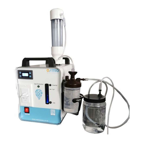
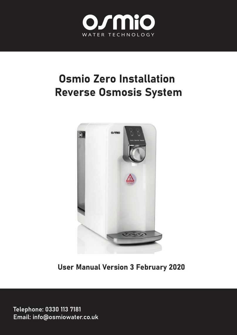
Osmio Fusion User manual

Contents
1. Safety Precautions
1.1 Power Safety Precautions
1.2 Setup Precautions
1.3 Usage Precautions
2. Product Description
2.1 Appearance Sketch Map
2.2 Display and Operation Interface
2.3 Product Specifications
3. Start Up
3.1 Introduction
3.2 Connecting the feed in valve
3.3 How to use quick connect fittings
3.4 installing the drain sadle
3.5 Connecting to the system
3.6 Power Connection
4. Use
4.1 Introduction
4.2 Flushing
4.3 Purification
4.4 Dispensing Water
4.5 Sleeping State
4.6 Power Off
5. Filter Maintenance
5.1 Introduction
5.2 Filter Replacement
5.3 Failure State
6. Common Usage Problem
7. Quality Assurance
8. After-Sale Service
9. Electrical Schematic Diagram

1 Safety Precautions
1.1 Power Safety Precautions
• The system should be plugged into a normal UK 3 pin plug at your home
or workplace and not be used in addition to AC 220-240V, 220V.
• Should be used in a grounding socket with rated current above 10A.
• Should only be used on an electrical circuit with RCD.
• Please do not use this product if the power cord or plug is damaged or
when the plug is loose.
• If there is dust or water and other foreign matter on the power plug,
please wipe it clean before use.
1.2 Setup Precautions
• The system should not be installed near heating equipment, electric
heating products or other high-temperature places.
• The system should not be installed in a place of possible leakage of
combustible gases or near any flammable substances.
• The system should only be used indoors and positioned on a stable flat
surface avoiding direct sunlight and moisture.
Thank you for purchasing this product, please read this manual carefully
before using the system, and keep it for future reference. If you have any
questions about this machine, please call our customer service centre on
0330 113 7181.
Take Note: Boiling water is potentially dangerous.
It is the responsibility of the owner to take sensible precautions when operating
the boiling water function of the system and to instruct other family members
and other new users to operate it safely.
KEEP OUT OF REACH OF CHILDREN

1.3 Usage Precautions
• On first use or if the unit has been idle for more than 2 days, run a
complete cycle and discard the first batch of water produced. Install the system
and then allow the machine to run until it fills the internal
tanks. Dispense both ambient and hot water to ensure both hot and cold
internal tanks are flushed.
• Unknown liquids or foreign objects are prohibited.
• If there is any water leakage from the machine, please disconnect the power
and contact the customer service centre. Please ensure tubing at the rear of the
• If there is any abnormal sound, smell, or smoke, etc., please disconnect the
power and contact the customer service centre.
• Do not disassemble or modify the system without professional guidance, please
contact the customer service centre if you need support.
• Do not move this product when it is in use.
• Do not use any detergent or alcohol based cleaner to clean the product, please
wipe the machine with a soft dry cloth.
• Do not grasp the water nozzle or the knob to move the machine.
• This product cannot be used by people who are physically or mentally disabled or
children unless supervised. Please keep it out of reach of children.
The filters on the system need to be changed every 6 months. We offer a 1 year
warranty. If you have water hardness over 250 ppm Calcium Carbonate Hardness
you may need to replace the carbon and membrane more frequently. The system
is designed to shut off if there is blockage in the membrane or prefilters. As the
system recirculates the rejected water from the membrane, the TDS level continu-
ally rises of the water entering the membrane filter. Therefore, for those with water
of higher TDS, more frequent membrane changes are required.
system and the filters have been inserted correctly and fully into the
system.

2 Product Description
2.1 Appearance
1. Display Panel
2. Control Button (Rotate & Press)
3. Drip Tray
4. Source water tubing
5. Waste water
6. Power Plug
FIGURE 1
Telephone: 0330 113 7181
Email: [email protected]

2.2 Display and Operation Interface
A. Normal Water
B. Warm Water(40℃-50℃)
C. Hot Water(80℃-88℃)
D. Boiled Water (90℃-98℃)
E. Filtering Water
F. Renew Water
G. Filter Maintenance
H. Rotate (Choose the Water Temp)
I. Press to Get Water
FIGURE 2

2.3 Product Specifications
Electrical Properties
Rated Voltage : 220 - 240 V
Rated Frequency : 50 Hz
Rated Power: 2200W-2600W
Heating System
Rated Heating Power: 2180W-2580W
Hot Water Capacity: 30 l/h (≥ 90°C)
Filter Stages
1 - Quick-Change activated carbon filter: removes chlorine and
organic impurities
2 - Quick-Change Membrane 50GPD: removes all pollutants and
flavours to almost 100%
3 - Quick-Change Insertion Filters: Hygiene post filter antibacterial:
removes 99% of the bacteria and viruses and improves the taste.
Volume
Pure Water Tank 1.5 L
Dimensions:
230mm Depth (320mm including drip tray)
183mm Wide
388mm Height
Weight’: 5 kg

3 Start Up
3.1 Introduction
• Please place the system in a cool, ventilated, solid horizontal surface, away
from any heat source.
2) PTFE the male end of the ball valve
3) Then using your spanner, screw the ball valve into the feed in valve and tighten it
with your spanner.
3.2 Connecting the feed in valve - Step 1: assembling the feed in valve
The feed in valve has 1/2” male
and 1/2” female and a tee off.
PTFE with 7 wraps the male
end of the feed in valve and the
male end of the blue lever ball
valve.
1) PTFE the male end of the feed in valve
1.
2. 3.
4.

Step 2: Connecting the feed in valve
The Feed in valve connects to the cold hose
of the existing cold tap on the sink.
Shut the water off and disconnect the
existing cold water hose. If your tap does
not use hoses then you can use another
adaptor. Please contact us for advice.
As the Feed in valve has male on one side
and female on the other side, it does not
matter which way around it goes.
All you need to do is connect the feed in
valve to the cold hose. Use the spanner
and wrench together to make it tight.
To connect the ball valve to the tubing for the
water filter, start by removing the nut on the blue
ball valve. Then place the nut over the tubing.
Push the tubing ontop the stem of the ball
valve. Ensure it has been pushed all the
way over the little ridge.
Use your wrench to tighten it up. The blue
lever is your on and off lever for turning
the water on and off. When the blue lever.
1.
2.
3.
4.
5.
6.

• They offer a significant time saving benefit over traditional connectors
• They tend to have less user failures compared to traditional connectors
• They require little skill or strength for their usage
• They do not require any tools to use and maintain them
Body
O-Ring
O-Ring Guide
Cap
Collet
Exploded Diagram of a Quick Connect Fitting
3.3 How to Use Quick Connect Fittings
Quick connect fittings (push fittings) are used in a wide variety of plumbing,
heating, electrical and fire suppression systems.
Quick connect works by
inserting the tubing into a connection mechanism that deploys fastening teeth
onto the tubing surface.
When opposing force is applied to the union, the teeth
are forced deeper into the tubing, preventing separation of the union.
The advantages of using quick connect fittings are:
Telephone: 0330 113 7181
Email: [email protected]

Step 1: It is essential that the outside diameter of the tubing being
inserted into the fitting is completely free of scratch marks, dirt and
any other material. Inspect the outside of the tubing carefuly.
Step 2: It is also very important that the sliced edge of the tubining is
cut cleanly. If the tubing needs to be cut, use a sharp knife or scissors.
Make sure to remove all burrs or sharp edges before inserting the
tubing into the fitting.
Step 3: The fitting grips the tubing before it seals. Lightly push the
tubing into the fitting until the grip is felt.
Step 4: Now push the tubing into the fitting harder until the tube
stop is felt. The collet has stainless steel teeth which hold the tubing
in position while the O-ring provides a permanent leak proof seal.
Step 5: Pull on the tubing away from the fitting and make sure it is
stays firmly in place. It is good practice to test the connection with
pressurized water before finishing installation.
Step 6: To disconnect the tubing from the fitting, ensure that the
system is depressurized first. Push in the collet squarely against
the face of the fitting. With the collet held in this position, the tubing
can be removed by pulling. The fitting and tubing can be reused.
How to Use Quick Connect Fittings
Push In Collet
Pull Tubing

Drain Saddle Installation Location
Drill here
Do not drill here
U-bend
1
2
3.4 Installing the drain sadle
The purpose of the drain saddle is to prevent the tubing connected to drain
from popping out of place and potentially leaking where the system is installed.
Please see the figure below for instructions on how to make the drain saddle
connection.
Step 1: Select a location for the drain hole based on the design of the plumbing.
The drain saddle should be installed above the u-bend if possible, on a vertical tail
piece. Locate the drain saddle away from the garbage disposal to prevent potential
contamination and system fouling. Please see figure below for a more detailed
explanation. Use a 7 mm (1/4”) drill bit to drill a small hole in the drain pipe for the
drain to pass through. Clean the debris from the plumbing and hold before
continuing.
Step 2: Remove the backing from the foam gasket and stick that half of the drain
saddle on the drain pipe so that the holes line up (a small drill bit or other long
narrow object can be used to help align correctly). Place the other half of the
drain saddle on the opposite side of the drain pipe. Clamp and loosely tighten
the drain saddle using the nuts and bolts included. Use a Phillips screwdriver to
tighten the drain saddle. Connect the tubing from the drain saddle quick
connection to the “Drain” connection on the system.
Drain Saddle Connection Diagram
1/4” Drain
Tubing
1/4” Bolt
1/4” Nut
Drain Saddle
Front Plate Drain Saddle
Back Plate
Foam Gasket
Drain Pipe
To “Drain”
Port on System

3.5 Connecting to the tubing
Fisrt Remove the blanking plugs by
following steps in section 3.3. Insert the
tubing, which is running from the feed
water, into the inlet. Place the ittle c-clip
back into place to avaid the pushfitting
disconnecting.
Insert one end of the tubing into the drain
saddle (also pushfit connection) and push
the other end into the outlet of the system
Inlet Outlet
4 Usage
4.1 Introduction
• At first, produce and dispense 5 litres of water which you then dispose of
by dispensing all the cold and hot water. This will flush out any loose filter
media. It is normal to see black water when using new filters.
• If there is water leakage from the machine, please disconnect the power
and contact the customer service centre. If there is any abnormal or
unexpected sound, smell, or smoke, etc., please disconnect the power and
contact the customer service centre.
4.2 Flushing
• After the setup, the machine automatically enters the flushing state and
works for 120 seconds. In the flushing state, the filtering symbol of the
display interface light will be on (see Figure 2) .
4.3 Purification
• After flushing, the machine automatically enters the filtering state. The
filtering symbol on the display interface light will be on (see Figure 2).
3.6 Power Connection
• Insert the power plug into the socket (see Figure 1). The system will beep and light
up which indicates the machine is ready to use.
Note: This product is only suitable for AC 220-240V, 220V power supply, and
should be used alone or over rated 10A with a earthed socket.

4.5 Dispense Water
• Place the water container on the tray (see Figure 1). Rotate the knob to
select the desired water temperature (Figure 3), and then click on (or push
on for 3 second) the middle part of the knob (see Figure 4) to dispense one
cup (or bottle) of water. Click the knob again if you want to stop getting
water. Note: the system will automatically stop water after 30 seconds if
you do not click the knob and will automatically stop after 60 seconds if you
hold the button for 3 seconds.
4.6 Sleeping state
• The system will automatically enter sleeping state when it is idle for more
than 1 hour. If there is any knob or button operation, it will immediately
return to service and then flush for 20 seconds.
4.7 Power off
• The system will automatically power off if the machine stays in sleeping
mode for 1 hour. If there is any knob or button operation, it will power on
automatically.
FIGURE 3 FIGURE 4

5 Filter maintenance
5.1 Introduction
First skip to section 5.2.4 to read about sanitisation and come back to this
section.
Use the company's certified filters. Disconnect the power. Do not disassem-
ble or attempt to modify this product.
5.2 Replacement of the carbon filter, reverse osmosis and
post filter
Step 1:
Open the back panel
Lift
Here
Step 2: Place the back panel
to the side
Help your environment and put all used filters
in recycled plastic waste

STEP 3 Starting at the base of the filter, tilt the filter towards you
slightly and rotate the Carbon Filter and Membrane filter clockwise
and remove them from the head.
5.2 Replacement of the carbon filter, reverse osmosis and
post filter,
STEP 4 Pull out the Post Filter slowly with your finger and insert a new
one fully.
STEP 5 Insert the new
insertion post filter into
the place of the old one.
Ensure that the filter is
in correctly. It should fit
snuggly and not stick out.
Membrane
Carbon

STEP 6 Start with the new
Carbon Filter so the label is
on the left hand side twist
the filter on anticlockwise.
Repeat the same with the
Membrane Filter.
STEP 7 Place the back
panel into its place at
the rear of the system.
5.2 Replacement of the carbon filter, reverse osmosis and
post filter,
Carbon
Membrane
STEP 8 Press and hold the button and
at the same time connect the power
plug to the socket. The beep sound
indicates the filter reset has completed.

5.2.4 Sanitisation
We suggest sanitising the system every 6 months prior to the filter change.
Contact your dealer to order the Fusion Sanitisation Kit.
1) Shut of the feed water by turning the lever of the feed in valve. Press the
button repeatedly to dispense all the water out of the internal RO storage tank.
2) Remove all 3 filters (Carbon Block, RO Membrane and the Post Remineralisa-
tion Filter). Insert the blank three filters in their place.
3)Instert the small piece of 1/4" tubing into the WHITE push fitting of the sanitis-
ing housing. Disconnect the 1/4" INLET tubing (this is the tubing from the
SUPPLY valve that goes to the system) and connect the this to the BLUE side of
the housing. NOTE: the housing has an arrow to show you the direction of flow
and it must be placed the correct way round, ensuring the arrow is pointing in
the flow direction.back on, add two Milton tablets, then wait for 5 minutes until
dissolved.
4) Place a milton tablet into the small housing and shut it. Open the feed in
valve to allow the water to fill up the housing and the machine. Let the machine
fill up and shut the feed in valve.
5)Let the system sit like this 30-60 minutes. Dispense all the water in the inter-
nal tank by pressing and holding the button. Disconnect the extra tubing and
sanitisation housing from the set up. Reconnect the tubing into the inlet of the
system.
6) Remove the sanitisation cartridges and replace them with new filters and
install a new set of filters.
7)After sanitisation the fastest way to clean all the sanitising fluid from the inter-
nal tank is to press the button repeatedly to dispense water until no more can
be dispensed from the internal RO storage tank, then allow the system 10-15
minutes for the system to refill the internal RO tank. Repeat this step until no
more sterilising solution can be detected...(usually 2 or 3 times). We recom-
mend you watch our short video of the sterilisation process.

5.3 Failure state
5.3.1 Purification exception
The system will show the purification exception state if the machine purifies
water for a long time and cannot stop, all the four temperature icons on the
display will flash. The machine may make louder noises leading up to this. This
happens when the Carbon Filter is blocked, and also the RO Membrane might
be blocked. First change the carbon block and see if the production rate goes
back to normal and if not, then also change the RO membrane. Also chanjge
the Sediment Filter and Remineralisation Filter too if they are 6 months old.
5.3.2 Burning alarm
The system enters the dry state if the heater works without water or the
temperature exceed the safe setting, the icon for hot water(80°C-88°C)will
blink, the machine can only dispense normal temperature water but cannot
dispense any kind of hot water. Solution: please contact our helpdesk.
Telephone: 0330 113 7181
Email: [email protected]

6 Common usage problems
If you have some problems during the usage, please check the problems by
following the guide below.
Usage Problems Likely Cause Suggested Solution
Power is disconnected.
Not pressing on the right
place.
Water shortage in
purified water tank,
“filtering” icon blinking.
Cannot dispense
ambient temperature
water
Check the power plug is
loose or not in place.
Press the button again.
Check the connections
on the rear of the filter.
Also check tubing for
kinks.
Cannot dispense hot
water
Power has only just been
connected and the
system needs time to
warm up
The machine is in the
state of "burn alarm".
Purified Water shortage
“filtering ”icon blinking.
Dispense a little bit of the
normal temp water first
then wait for 15 minutes
and then dispense hot
water.
Dispense ambient tempera-
ture water several times
then retry dispensing hot
water.
Wait for moment until the“
filtering ”icon light is on all
the time then dispense hot
water.
Machine does not filter Tubing leading up to the
filter is blocked
Tubing leading up to the
filtration system is kinked
Check tubing for any debris or
blockages
Straighten out the tubing.
Table of contents
Other Osmio Water Filtration System manuals
Popular Water Filtration System manuals by other brands

Eljen
Eljen Mantis M5 Series Installation and System Design Guide

Mitsubishi
Mitsubishi FR-BIF-H Series quick start guide

Eaton
Eaton DCF 400 Installation operation & maintenance

Tersano
Tersano iClean mini instructions

Hozelock
Hozelock bioforce 12000UVC operating instructions

SuperFish
SuperFish Alu Tech UVC 40000 user manual