Osram Clay Paky Scenius Spot Use and care manual

SCENIUS SPOT
PARTS
REPLACEMENT
GUIDE
Rev. July, 29th 2016 - ENGLISH

SCENIUS SPOT
PARTS REPLACEMENT GUIDE
ENGLISH
July, 29th 2016
Page 2 of 48
INDEX
1. CAUTIONS...........................................................................................................................................................3
2. WARNINGS..........................................................................................................................................................3
3. NEEDED TOOLS.................................................................................................................................................3
4. PRELIMINARY OPERATIONS AND GENERAL MAINTENANCE......................................................................4
4.1. Pan - tilt locking and releasing...................................................................................................................4
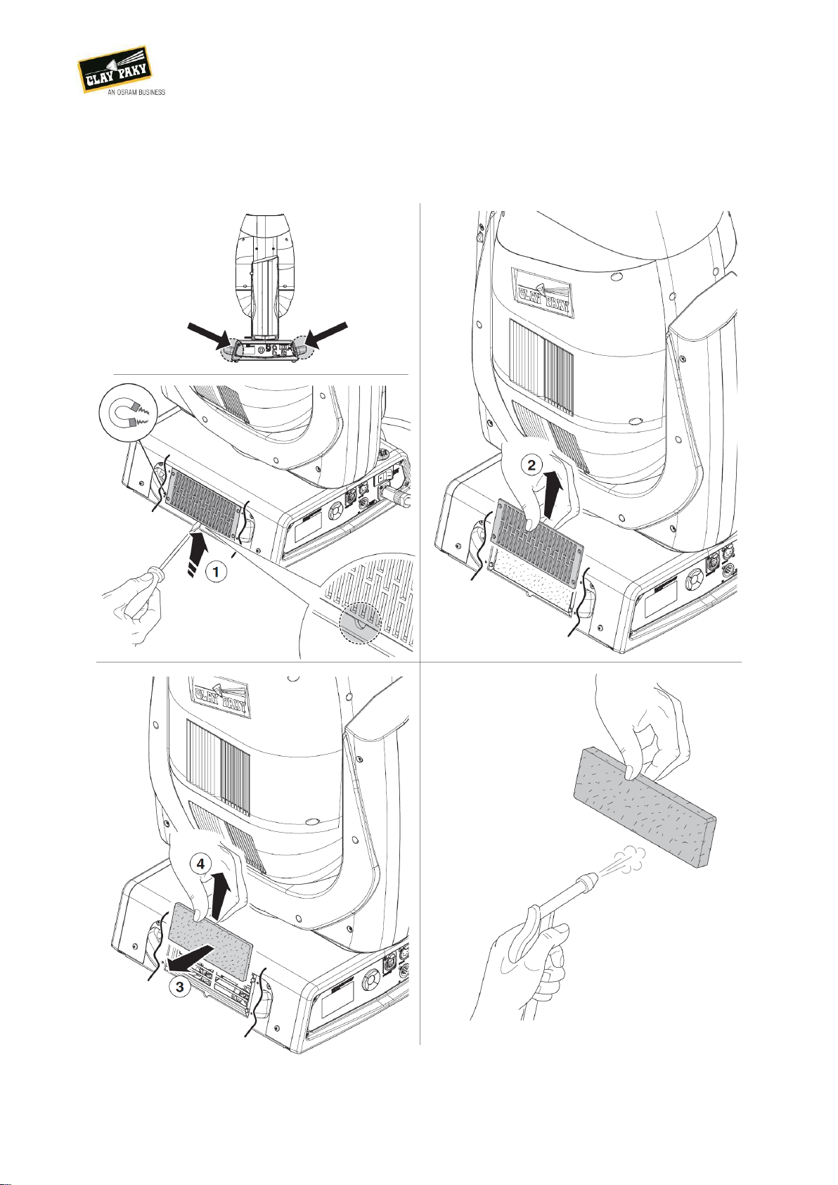
4.2. Dust filters cleaning / replacement.............................................................................................................5
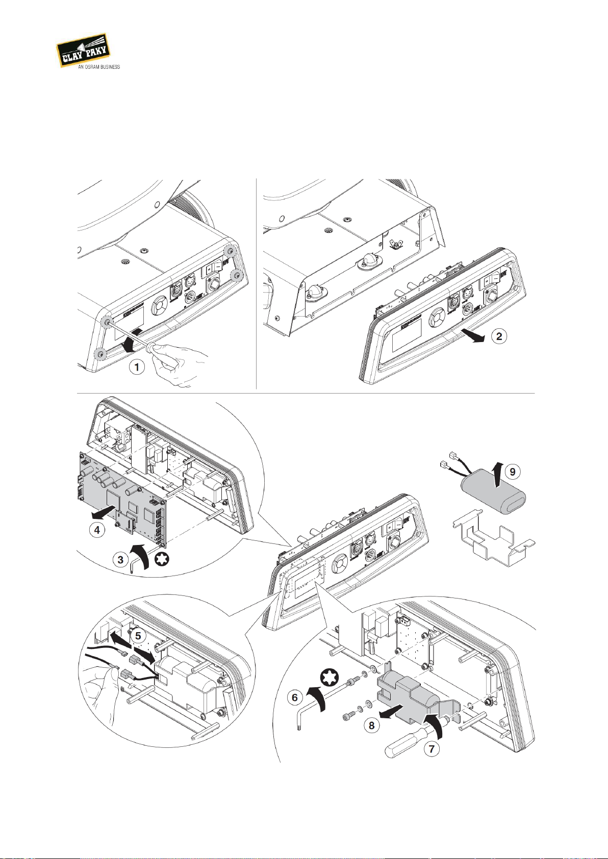
4.3. Battery removal..........................................................................................................................................6
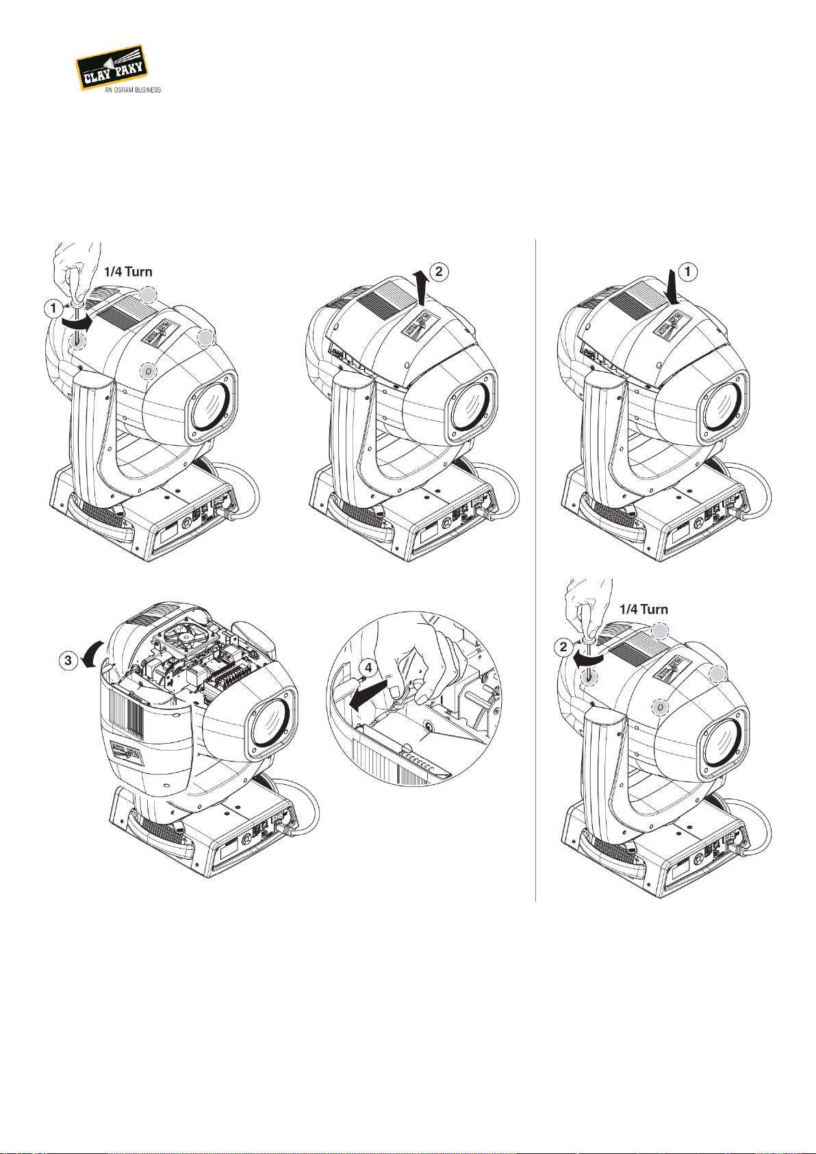
4.4. Head covers opening and closing..............................................................................................................7
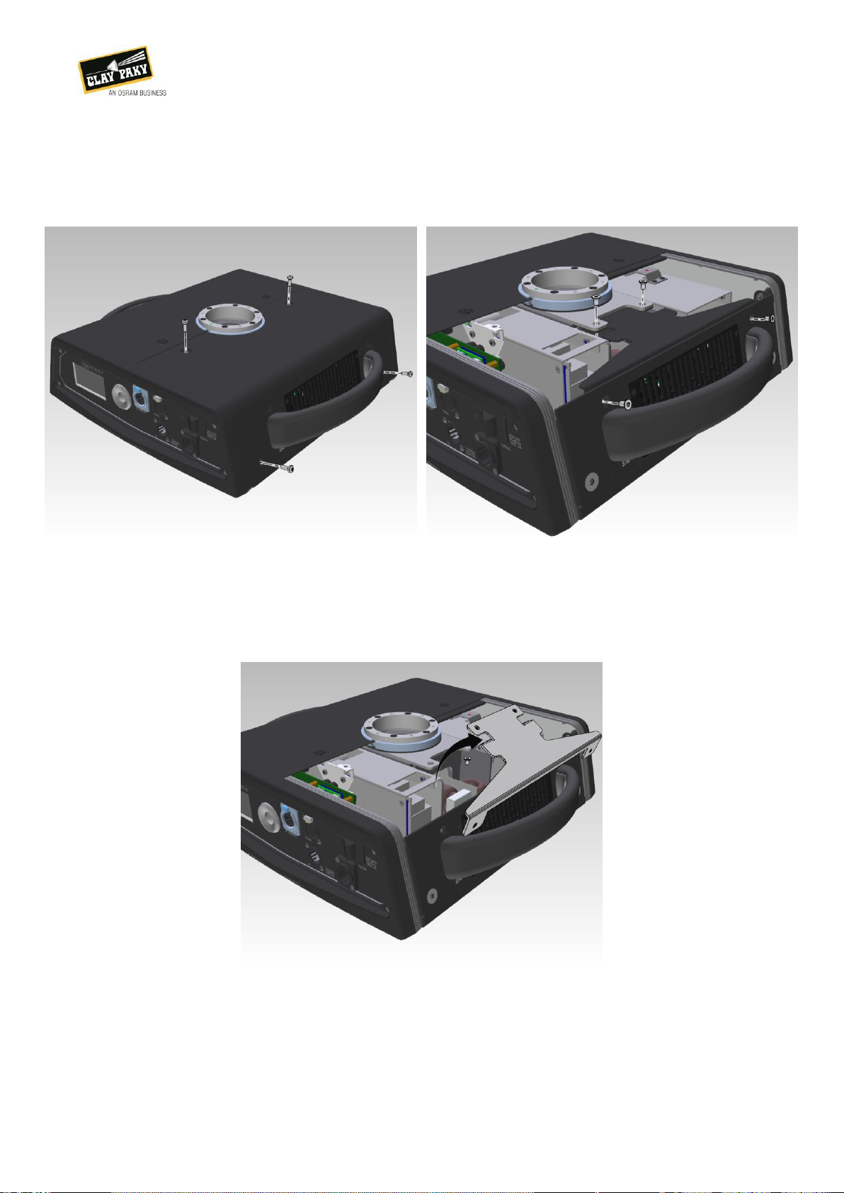
4.5. Covers opening / Base protections removal ..............................................................................................8
4.6. CMY module removal.................................................................................................................................9
4.7. Effects module removal............................................................................................................................10
4.8. Optics removal .........................................................................................................................................11
4.9. Pan - tilt effects disabling.........................................................................................................................12
4.10. Lamp - effects functional check................................................................................................................13
4.11. Optical parts cleaning...............................................................................................................................14
5. BASE / YOKE PARTS REPLACEMENT ...........................................................................................................15
5.1. Power supply replacement.......................................................................................................................15
5.2. Lamp driver replacement .........................................................................................................................17
5.3. EMI filter replacement ..............................................................................................................................21
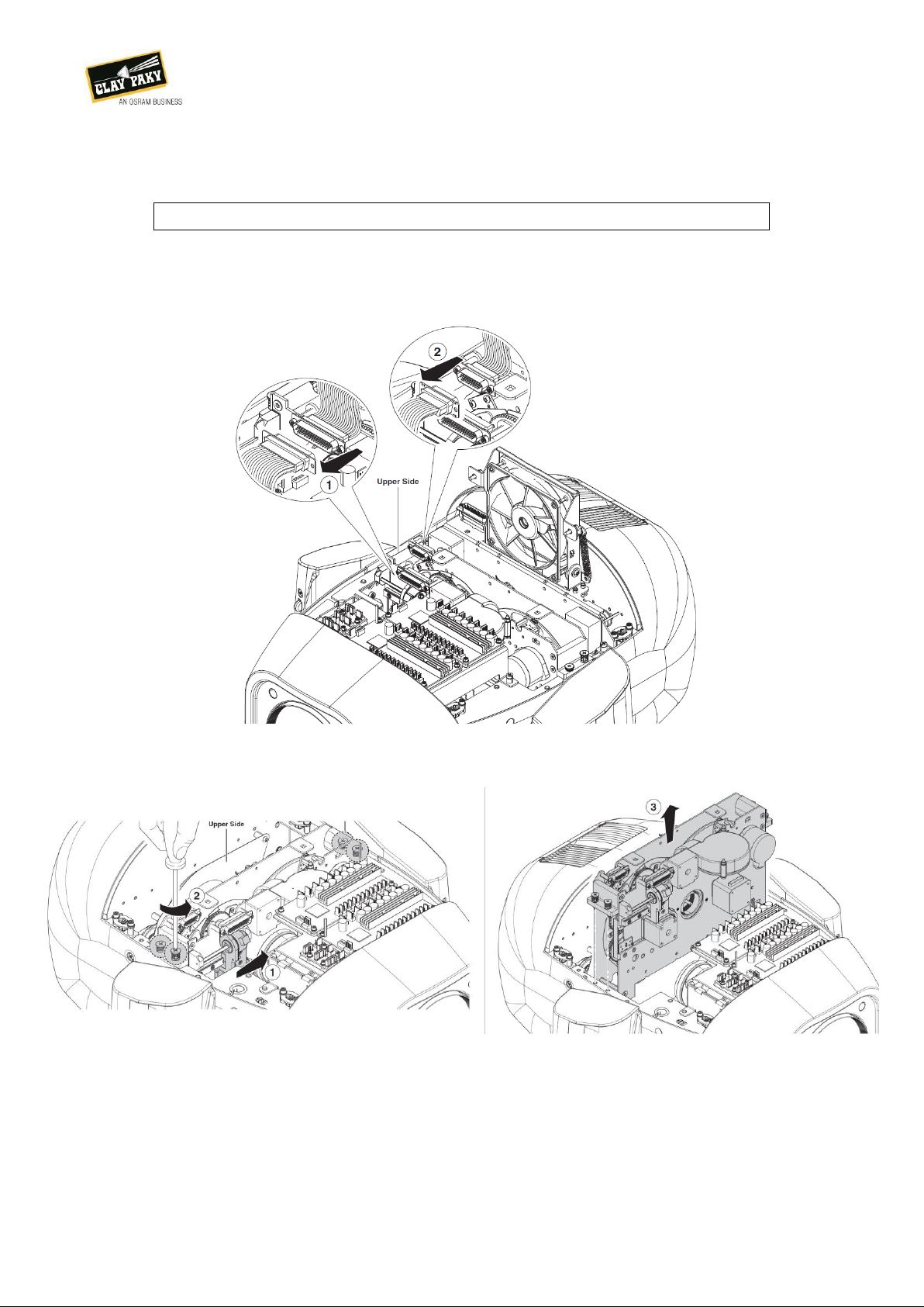
5.4. CPU replacement.....................................................................................................................................22
5.5. Pan - tilt PCB replacement.......................................................................................................................24
5.6. Tilt lock assembly replacement................................................................................................................25
5.7. Tilt motor replacement .............................................................................................................................26
6. HEAD PARTS REPLACEMENT........................................................................................................................29
6.1. Front cover / front lens replacement ........................................................................................................29
6.2. Zoom lens replacement............................................................................................................................30
6.3. Focus lens replacement...........................................................................................................................32
6.4. Frost filters replacement...........................................................................................................................34
6.5. Prism assembly replacement...................................................................................................................37
6.6. Effects module splitting ............................................................................................................................39
6.7. Animation wheel replacement..................................................................................................................40
6.8. Rotating gobo wheel 2 replacement.........................................................................................................40
6.9. Iris replacement........................................................................................................................................43
6.10. Rotating gobo wheel 1 replacement.........................................................................................................44
6.11. Color wheel replacement .........................................................................................................................46
6.12. Strobe blades replacement ......................................................................................................................47
6.13. Color mixing flags replacement................................................................................................................48

SCENIUS SPOT
PARTS REPLACEMENT GUIDE
ENGLISH
July, 29th 2016
Page 3 of 48
1. CAUTIONS
Ensure the unit is physically not connected to any electric line when unnecessary;
Allow the unit to cool down before performing operation;
Wear transparent safety glasses to prevent small parts or springs to cause eyes injury;
Wear suitable protective gloves when handling broken glass-like parts;
2. WARNINGS
Before performing any operation, be sure to completely read and understand all the related
instructions, including the preliminary and final actions;
Always use electrostatic bags for sensitive electronic parts;
Watch out not to lose any parts (especially shaft spacers) during disassembling operation;
Ensure not to scratch glass part when removing metal based ones.
3. NEEDED TOOLS
PH2 Phillips screwdriver
PH1 Phillips scre7wdriver
PH0 Phillips screwdriver
T20 Torx screwdriver
T10 Torx screwdriver
Thin flat screwdriver
5.5mm nut spinner
7mm nut spinner
1.5mm T-shaped Allen key
2mm T-shaped Allen key
2.5mm T-shaped Allen key
3mm T-shaped Allen key
4mm T-shaped Allen key
1 L-shaped Allen key set
1 L-shaped Torx key set
5.5mm nut driver
7mm nut driver
Electrician scissors
Crooked nose pliers
Nippers

SCENIUS SPOT
PARTS REPLACEMENT GUIDE
ENGLISH
July, 29th 2016
Page 4 of 48
4. PRELIMINARY OPERATIONS AND GENERAL MAINTENANCE
4.1. Pan - tilt locking and releasing

SCENIUS SPOT
PARTS REPLACEMENT GUIDE
ENGLISH
July, 29th 2016
Page 5 of 48
4.2. Dust filters cleaning / replacement

SCENIUS SPOT
PARTS REPLACEMENT GUIDE
ENGLISH
July, 29th 2016
Page 6 of 48
4.3. Battery removal
At the end of the fixture / battery life proceed as following illustrated. If removing the battery, dispose
of it according to the applying regulations!

SCENIUS SPOT
PARTS REPLACEMENT GUIDE
ENGLISH
July, 29th 2016
Page 7 of 48
4.4. Head covers opening and closing

SCENIUS SPOT
PARTS REPLACEMENT GUIDE
ENGLISH
July, 29th 2016
Page 8 of 48
4.5. Covers opening / Base protections removal
Locate and, using a PH1 screwdriver, loosen the
4 fixing screws to free the carter
Locate the other 4 screws and remove them as
well, if needed.
Remove the internal protection and store it in a
safe place
If needed, perform the same operation on the
opposite side of the base.

SCENIUS SPOT
PARTS REPLACEMENT GUIDE
ENGLISH
July, 29th 2016
Page 9 of 48
4.6. CMY module removal
Preliminary / final Actions
Head covers removal;
Lamp - effects functional check.
Remove the marked connector pulling it gently
Loosen the marked screws, then remove the module ensuring both fans are in the open position

SCENIUS SPOT
PARTS REPLACEMENT GUIDE
ENGLISH
July, 29th 2016
Page 10 of 48
4.7. Effects module removal
Preliminary / final Actions
Head covers removal;
Lamp - effects functional check.
Remove the marked connector pulling them gently
Remove the circled screws to extract the effects module

SCENIUS SPOT
PARTS REPLACEMENT GUIDE
ENGLISH
July, 29th 2016
Page 11 of 48
4.8. Optics removal
Push the focus lens to the inside, then loosen the 4 highlighted screws.
Extract the optics module from the unit body.

SCENIUS SPOT
PARTS REPLACEMENT GUIDE
ENGLISH
July, 29th 2016
Page 12 of 48
4.9. Pan - tilt effects disabling
This dip switch settings are the correct ones for
normal use
This dip switch settings will disable the pan / tilt
drivers, leaving the head free to move
When head movement is not needed, ensure
both pan / tilt locks are engaged to prevent
unwanted head movement.
Sticking a piece of tape to the unit’s shoulder
will help you remind to reactivate the pan / tilt
functions.

SCENIUS SPOT
PARTS REPLACEMENT GUIDE
ENGLISH
July, 29th 2016
Page 13 of 48
4.10. Lamp - effects functional check
Connect the unit to the mains supply voltage via
a PowerCon, release pan and tilt locks and close
the breaker, then wait for the unit to perform the
automated reset routine
After the unit moves to home position, connect a
DMX 512 console to it and point the head to a
test wall
Using the control panel or DMX desk (ch 32),
strike the lamp and set the unit to open white
Check for stable and continuous light output and
effects movement

SCENIUS SPOT
PARTS REPLACEMENT GUIDE
ENGLISH
July, 29th 2016
Page 14 of 48
4.11. Optical parts cleaning

SCENIUS SPOT
PARTS REPLACEMENT GUIDE
ENGLISH
July, 29th 2016
Page 15 of 48
5. BASE / YOKE PARTS REPLACEMENT
5.1. Power supply replacement
Preliminary / final Actions
Base covers removal;
Lamp - effects functional check.
Needed Parts
Electronic power supply assembly (P/N: 283220/801);
Thermal pad for Scenius power supply (P/N: 264102/001).
Open the front panel removing the 4 circled
screws with a PH2 screwdriver, then remove the
carters as well.
Detach the spade connectors, then press the
lever of the middle connector to set in free.
Lastly, locate and remove the ground spade
connector on the right, bottom side
Locate and remove the 3 screws one the base
backside

SCENIUS SPOT
PARTS REPLACEMENT GUIDE
ENGLISH
July, 29th 2016
Page 16 of 48
Ensure the thermal pad is still in good
conditions, in case replace it as well
Extract the old SMPS and put the new one in
place, plugging the ground first
Plug the remaining connectors respecting their
polarity, and then check the unit for proper
functioning.

SCENIUS SPOT
PARTS REPLACEMENT GUIDE
ENGLISH
July, 29th 2016
Page 17 of 48
5.2. Lamp driver replacement
Preliminary / final Actions
Base covers removal;
Lamp - effects functional check.
Needed Parts
Lamp power supply assembly (P/N: 283321/801);
Thermal pad for lamp power supply (P/N: 264101/001).
Rest the fixture as shown in the picture
Using a T20 screwdriver, remove the 3
highlighted screws, then put back the unit on its
feet.
Remove the back carter to clearly see the
ballast
Gently push the release lever to free the control
cable

SCENIUS SPOT
PARTS REPLACEMENT GUIDE
ENGLISH
July, 29th 2016
Page 18 of 48
Loosen the two nuts keeping in place the air
duct
Slide the air duct towards the inside, then lift it to
remove it.
Partially lift the lamp power supply, release the
fan connector and then the spade connectors on
the left side.
Slightly pull the fan to elongate the shock
absorbers, keep them in position using a pair of
pliers and remove the fan only

SCENIUS SPOT
PARTS REPLACEMENT GUIDE
ENGLISH
July, 29th 2016
Page 19 of 48
Disconnect the ground first, than the DC input
releasing the lever on the connector.
Reconnect the ground, then plug in the
connector. Do not pass the wires
where the fan will be located!
Pass the tip of the shock absorbers through the
fan’s holes, then slide them keeping the base in
position.
Plug in the spade connectors, ensuring the
connectors didn’t get loose.
If so, tighten them using a plier.

SCENIUS SPOT
PARTS REPLACEMENT GUIDE
ENGLISH
July, 29th 2016
Page 20 of 48
Plug in the lamp control wire, too, then restore
the fan air duct as well.
Ensure the thermal pad is correctly in place.
Should it move, fix it using a tiny drop of joint
compound.
Turn the unit on a side, then put back the fixing
screws.
Put the carters back in place, then check for
proper working.
Table of contents
Other Osram Dj Equipment manuals

Osram
Osram CLAYPAKY AXCOR PROFILE 900 User manual

Osram
Osram KREIOS PROFILE 80W WW User manual

Osram
Osram Claypaky CloudIO User manual

Osram
Osram KREIOS PAR162W VNSP IP 100-240V User manual

Osram
Osram BY-P05 User manual

Osram
Osram BY-P23B User manual

Osram
Osram BY-P12 User manual

Osram
Osram Clay Paky MYTHOS User manual

Osram
Osram BY-P06 User manual

Osram
Osram ADB Stagelight LEXPERT PROFILE L User manual