Outdoor Plus OPT-ESTOPTM Quick start guide

DESCRIPTION
The 1-Hour Gas Timer with E-Stop is an emergency shut-off, mechanical timer, and manual shut-off gas valve
designed to be installed on the inlet side of a gas appliance to enable the user to control the time gas is allowed to
flow to a gas appliance. This is a mechanical timer (no batteries or power required) that has the ability to control
gas flow for 1-hour (60 minutes). In addition, both models have an emergency shut-off (red knob) that enables the
user to quickly and easily shut the gas completely OFF, should the need arise.
The 1-Hour Gas Timer with E-Stop body is 4-inches high x 2 ⅞ -inches wide x 2 ⅛ -inches deep and can replace a
manual shut-off valve and meet local code requirements as the accessible shut-off valve. It can be use for
multiple applications (indoor or outdoor) from gas fire pits, gas grills, gas logs, gas torch lights, etc., wherever a
shut-off valve is a requirement or a specified by a customer.
PUSH TO STOP
TURN TO START
OFF
TURN
PAST 20
40
60
MINUTES
SPECIFICATION
Pipe Size: ½” NPT (2) inlets and (2) outlets Maximum Pressure: ½” PSI
CSA Rated Capacity: 165,000 Btu/Hr at 1” Pressure Drop (NG) Ambient Temperature: 0°F to 175°F (79°C)
Timer Accuracy: 60 Min. +/- 15% or 2.5 Hrs.+/- 15% Inlets: Have fine mesh screens to filter any debris
Multiple Mounting Holes: Uses 3/16-24 machine threads Designed For: Natural or LP Gas (no conversion required)
CSA Certified: Tested to ANSI Z21.21; CSA 6.5
WARNING
•Read these instructions carefully. Failure to follow these instructions completely could damage the product or
cause a hazardous condition.
•Check the ratings given in the instructions and on the product your installing to make sure the E-Stop Gas
Timer is suitable for your application. See description below.
•Installer must be a trained, experienced service technician or gas plumber.
•After installation is complete, check out product operation as provided in these instructions.
1-Hour Gas Timer
with E-Stop
Models:
OPT-ESTOPTM
Owner's Operation and
Installation Manual
www.TheOutdoorPlus.com
Page 1
909-460-5579
CALIFORNIA PROPOSITION65
WARNING
This product can expose you to Chromium, which is known to the state of
California to cause cancer and birth defects or other reproductive harm.
(For more information, go to: www.p65warnings.ca.gov)
4 /”
TYP
2 /”
TYP
C
L
C
L
C
L
3/16 - 24
Mounting Hole
3/16 - 24
Mounting Hole
3/16 - 24
Mounting Hole
3/16 - 24
Mounting Hole
PUSH TO STOP
TURN TO START
OFF
TURN
PAST 20
40
60
MINUTES
BACK VIEW
4”
2 /”
2¹/”
³/”
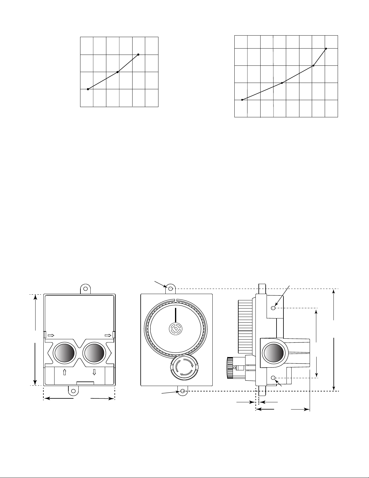
Fig. 1 E-Stop Gas Timer mounting hole locations applicable to both models.
MOUNTING
The 1-Hour Gas Timer with E-Stop has the ability to be mounted from the side of the body, using the four (4)
provided holes (two mounting holes per side) or using the two mounting hole tabs at the top and bottom of the
body when facing forward. Each mounting hole uses 3/16 - 24 machine screws to secure it into position. Note: We
recommend using stainless steel screws for any outdoor applications. See Fig. 1 for details.
2.0” Inlet @ 1.0” Outlet =
0.5
1.0
1.5
2.0
2.5
3.0” Inlet @ 1.5” Outlet =
4.0” Inlet @ 2.0” Outlet =
250,000 275,000 300,000 325,000 350,000 375,000 400,000
Btu/Hr
Pressure Drop & Capacity Curve
E-Stop Timer (LP Gas)
5.0” Inlet @ 2.5” Outlet =
3.0
425,000 450,000
Note: Pressure drop information listed is generated in American Flame lab and is to be used as reference only.
Table 2 Pressure drop and capacity for LP Gas).
2.0” Inlet @ 1.0” Outlet =
0.5
1.0
1.5
2.0
2.5
3.0” Inlet @ 1.5” Outlet =
4.0” Inlet @ 2.0” Outlet =
150,000 175,000 200,000 225,000 250,000 275,000 300,000
Btu/H
Pressure Drop & Capacity Curve
E-Stop Timer (Natural Gas)
Table 1 Pressure drop and capacity for Natural Gas.
www.TheOutdoorPlus.com
Page 2
909-460-5579

INSTALLATION
The recommended installation position is up-right as shown
in Fig 2, view "D". It has two (2) inlet and two (2) outlet gas
connections. The diagrams below provide possible ways to
plumb the E-Stop (See Fig. 3). Two (2) ½” NPT plugs are
provided with the E-Stop. Plug the inlet and outlet
connections not being used for the application. Connect gas
supply to the inlet with the arrow pointing into the
valve. Connect outlet side to the gas appliance (See Figs. 2 &
3 for details).
NOTE: Conduct a gas leak test on the E-Stop Gas Timer after
plumbing is complete.
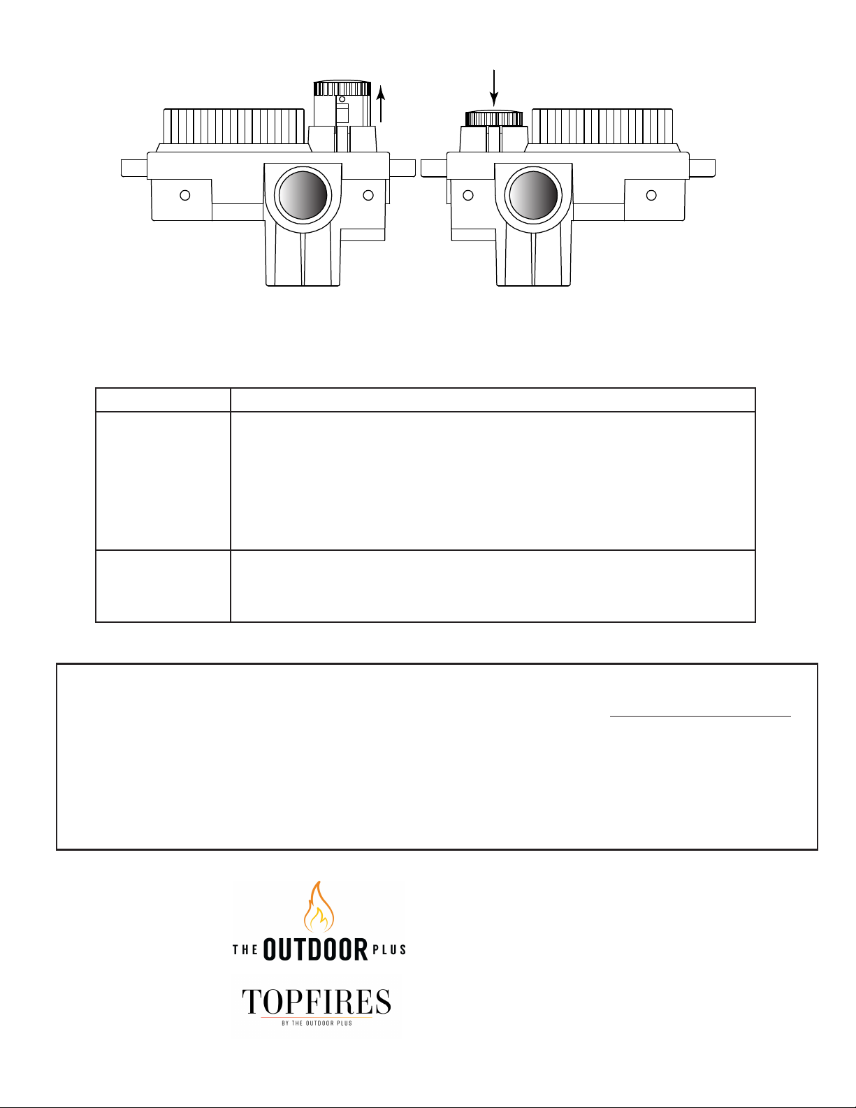
OPERATION
TO TURN ON
Step 1: Rotate the clear timer dial past 20 (ESTOP1-0H) or
past 0.5 (ESTOP2-5H) to set the time. Timer will begin
“ticking” when the dial is turned while the countdown time
is set. Step 2: Turn red knob clockwise (about a ¼ turn)
until it pops outward. Gas will now flow to enable you to
light the appliance.
TO TURN OFF:
Let timer expire or simply press red knob inward until it
stops. The red knob will lock down with a “click” and stop
gas flow. See Fig. 4 and Fig. 5 on following page.
Note: Do not force the timer dial to the OFF position after
time is set (This will weaken the spring inside the timer body
and affect the accuracy of the time).
Timer Dial:
Rotate clockwise to
start time. Adjust dial
to desired time frame.
Red Knob:
Turn clockwise and
knob will “pop” up
to allow gas flow.
PUSH TO STOP
TURN TO START
OFF
TURN
PAST
20
40
60
MINUTES
Fig. 4 E-Stop operation.
BACK VIEW
Inlet
Inlet
Outlet
Outlet
SIDE IN SIDE OUT
BACK
IN
BACK
OUT
Fig. 2 Inlet and outlet connections.
“A-C” Shows Top View of E-Stop
Inlet
Outlet
D
“D” Shows Front View of
E-Stop
PUSH TO STOP
TURN TO START
OFF
TURN
PAST
20
40
60
MINUTES
Inlet
Outlet
C
Inlet
Outlet
B
Inlet
Outlet
A
Fig. 3 Plumbing options
www.TheOutdoorPlus.com
Page 3
909-460-5579
Limited Warranty
TOP warrants the 1-Hour Gas Timer with E-Stop for 12 months from the date of purchase to the original
purchaser to be free from defects in materials and workmanship. It is designed for INDOOR OR OUTDOOR USE.
Damage to the 1-Hour Gas Timer with E-Stop caused by accident, misuse, abuse, or installation error, whether
performed by a contractor, Service Company, or owner, is not covered by this warranty. TOP will not be
responsible for labor charges and/or damage incurred in installation, repair, replacement, or for incidental or
consequential damage. Some states, provinces, and nations do not allow exclusion or limitations of incidental or
consequential damages, so the above limitations or exclusions may not
apply. This warranty gives you specific legal rights. You may also have other rights that vary by state, province, or
nation.
Symptom Remedy
No gas flow 1. Rotate dial beyond the "turn past" position.
2. Ensure red knob is protruding outward in ON position.
3. Has time has expired on timer? If so re-start timer again.
4. Ensure primary gas supply is turned ON.
5. Ensure the gas timer is plumbed properly.
6. Look for any physical damage.
7. Ensure other gas valves before or after the timer are operating.
8. Check inlet mesh screen for debris blockage.
Gas flow won't stop 1. Timer plumbed backwards? Check inlets and outlets on timer.
2. Excessive gas pressure exceeding the ½” PSI maximum pressure.
3. Plumbed into both inlet lines and not one of the outlets.
4. Look for any physical damage. If so, replace timer.
Red Knob Down = Gas OFFRed Knob Up = Gas ON
Side View Side View
Fig. 5 E-Stop Gas Timer red knob positions
TROUBLESHOOTING
www.TheOutdoorPlus.com
Page 4
909-460-5579
The Outdoor Plus Co, Inc
235 East Main St
Ontario CA 91761
Phone: 909-460-5579
Fax: 909-460-5530
www.TheOutdoorPlus.com
www.TopFires.com


