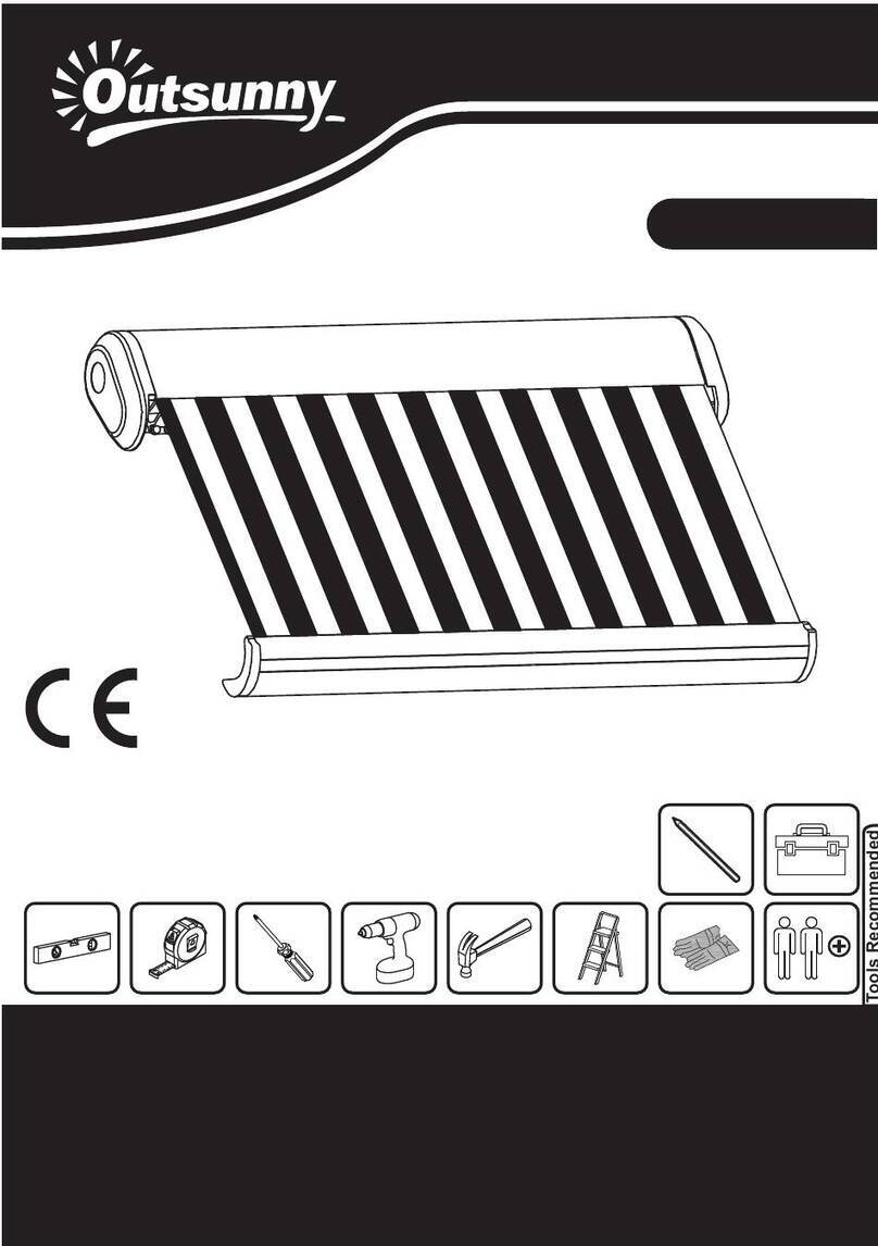
Outsunny 840-245V80 User manual

EN_IMPORTANT, RETAIN FOR FUTURE REFERENCE: READ CAREFULLY.
FR_IMPORTANT:A LIRE ATTENTIVEMENT ET À CONSERVER POUR CONSULTATION
ULTÉRIEURE.
ES_IMPORTANTE, LEA Y GUARDE PARA FUTURAS REFERENCIAS.
PT_IMPORTANTE, RETER PARA REFERÊNCIA FUTURA: LEIA ATENTAMENTE.
DE_WICHTIG! SORGFÄLTIG LESEN UND FÜR SPÄTER NACHSCHLAGEN AUFBEWAHREN.
IT _ IMPORTANTE! CONSERVARE IL PRESENTE MANUALE PER FUTURO RIFERIMENTO E
LEGGERLO ATTENTAMENTE. US_CAUS_CA
IN221100757V01_US_CA_840-245V80_840-245V81_840-245V82

1

2

3
NK^ïåáåÖ=Ñê~ãÉ=^=uNéÅ
2.Awning frame B X1pc
3.Fabric tube A(with motor
dowel) X1pc
4.Fabric tube B(with round
dowel) X1pc 5.Fabric with valance X1pc 6.Manual rotary lever X1pc
7.Front bar connecter X1pc 8.Square bar connecter
X1pc
9.Fabric tube connecter
X1pc
10.Fabric fixer X2pc 11.Wall bracket 12.Expansion
bolt(M10*100)
13.Retaining bolt(M8*55)14.Hand-crank X1pc 15.Screw (M4*16) X20pc
16.Manual X1pc
17.Motor regulating rod
X1pc 18.Right front bar end
19.Latch 20.Remote control

4
11.Wall bracket
12.Expansion
bolt(M10*100)
13.Retaining
bolt(M8*55)
IF YOU CAN NOT FIND THE PARTS 7,8,9 IN PACKAGE, THESE PARTS MAYFALL
INSIDE, PLEAES TAKE THEM OUT.

5
Awning assembly steps
WARNING:DO NOT REMOVE THE SAFETY SLEEVES FROM THE ARMS UNTIL
INSTRUCTED TO DO SO.
Insert the connectors(7) and (8) into 1.And fix the screw.
39
15 *4
*6
15
18
7
3*4
15 4
4
3
12
*6
15

6
Insert the latch(19) to the hole, and unfold it to fix the roller(3).
Insert the fabric(5) to the hole of the fabric tube(3,4) and the Awning frame(1,2)
Insert the maunal rotary lever(6) , and fold the fabric by hand-crank(14).
ATTENTION :Please keep the fabric symmetrical in the fabric tube(3,4)and the
Awning frame(1,2) .Otherwise it may destroy the awning when the motor works.
5
3 4
5
1 2

7
10 10
10 10
Insert the fabric fixer(10) into(4) and (2).And fix them
2
18

8
Cross section of awning
20cm
Above
door frame
Slope can
be adjusted
Door
Wall
Draw a horizontal line in the
position of the required height.
Wall bracket
20cm above
Door frame
Wall bracket
Patio Doors
16MM MASONARY
DRILL
INSERT WALL BOLT
CROSS SECTION OF WALL WASHER
SAFETY BOLT
^êã
Front Bar
Awing Fabrc
Helper
Lateral Arm
Arm
clamp
(se inset)
Jack Bolt
Locking Nuts

9
Step 1: Unboxing.
Carefully remove the awning from the box and remove the styrofoam protectors
from the awning, remove the plastic bags and plastic guards from the awning and
carefully place the awning aside to avoid having it damaged by scratches or
otherwise damaged or soiled during assembly.
Think about how you will be securing the awning to the wall ahead of time. In case
you would like to mount it above a patio door, you should leave a space of at least 8
inches (20cm) above the door frame. If there is enough space available above the
door frame.
The approximate total drop area of the awning is around 12-20 inches (30-50
cm),Ensure that you also take this drop height into account in your decision on
where to install the awning.
The drop angle can and may only be changed minimally.
Picture 1: it shows the drop still be changed after assembly. The ideal drop angle,
however, has already been set in the factory of the awning when it is fully extended.
(Total drop, height of front bar more than 8 Feet (≥2.5 meters), cross section of the
wall, bracket height).
Step 2: Location of the wall brackets
Location (a) - Between the right end of the awning and the right Arm. (facing the
awning) on the fabric tube.
Location (b)- Only available for 3.5m and 4m.
Location (c) - Between the left end of the awning and the left Arm.
Measure the width of the awning with a ruler and note the positions of wall brackets.
Picture 2:Draw a horizontal line at the height of the required areas as illustrated in
the image and use a long ruler, a level and chalk for this purpose. Mark the
corresponding places on the wall by running a pencil through the holes at the
bottom of the brackets.
Wall
brackets
Location©
Wall
brackets
Location(b)
Wall brackets
Location(a)Only Available for 3.5m and 4m.

10
CAUTION: PROPER LOCATION OF THE BRACKETS IS THE MOST IMPORTANT
ASPECT OF THE AWNING INSTALLATION. IT IS CRITICAL THAT YOU FASTEN
ALL THE MOUNTING BRACKETS TO STUDS, JOISTS, HEADERS OR OTHER
MAJOR STRUCTURAL COMPONENTS.
WARNING: FAILURE TO SECURELY FASTEN ALL THE BRACKETS TO THE WALL
COULD RESULT IN THE COLLAPSE OF THE AWNING AND CAUSE PERSONAL
INJURY OR DEATH.
Step 3: Drill the holes.
Use a 14 mm masonry drill bit to drill the holes for the brackets at the appropriate
marks on the wall.
Picture 3:The holes should be 4 inches (9cm) deep in the wall and must be drilled
through solid brick or concrete. Do not drill through mortar because this does not
offer the support that is required for the awning.
Installation on timber houses and sheds:
The awning can also be installed on timber houses if their walls can carry the
weight of the awning. In this case, ensure the brackets are firmly secured to the
outside of solid wooden beams.
The anchor bolts from the delivered package are not suitable for mounting the
awning to wooden beams. Instead buy carriage bolts of adequate length and of an
appropriate diameter and secure the awning with them.
Step 4: Attachment brackets for wall:
Picture 4:After inserting the wall bolt, add the washers and then the wall brackets.
Now place the washers on the bolt head and firmly tighten the 17mm nuts.
Note:
1. It may be necessary to drive the anchor bolts in with a wooden mallet because
they do not go in easily. Do not use a metal hammer for this purpose because this
could damage the threads on the top of the bolts.
2. If the bolts need to be driven into the wall with a hammer, we recommend initially
placing the nut on the screw loosely(only placing it loosely on the bolt) because this
avoids damaging to the bolt threads.
3. Firmly tighten the bolts with a 17mm hex key: it is best to use a hex key with a
closed end rather than an open end because this will avoid damaging to the nut of it
should slip.
4. As soon as they are fully inserted, the brackets must sit firmly in the wall. If they
are still moving in some direction you must further tighten it.
5. Do not try to secure the wall brackets to loose wall stones or any surfaces that
are not absolutely firm.
6. Ensure that the wall brackets are screwed firmly to the wall, so that they can in no
case tear out when the awning is being installed.

11
Step 5: Now your awning can be secured to the wall brackets.
Picture 5:At least two ladders or chairs are required to install the awning in order to
obtain the required height. Ensure that the ladders or chairs are firmly stay on the
ground so that you can't fall.
Use ladders that are suitable for such assembly work.
Note:
In case the pole( wall bar) can' t be inserted into the wall brackets, you should
slightly loosen the wall brackets screws and then try it again.
This time, move the awning slightly forward and backward until the pole slips into
the brackets.
Then immediately insert the safety bolts on the front side of the wall brackets and
tighten the nuts with a 19mm hex key.
Ensure that the safety bolts for the wall brackets have been tightly secured.
Note: Now you could remove the safety sleeves from the arms.
Step 6: Changing the Pitch
There is one final adjustment you might need to make. It is setting the pitch or angle
of your awning. Fully open the awning.
Are you happy with the height and level of the front bar? If so, great!
You are done with the installation. Relax, and enjoy your awning.
If not, you can adjust the pitch or angle of each arm separately.
1. Fully open the awning using your crank or remote transmitter on motorized
awning, unplug the power cord from the outlet after opening the awning.
2. Using 17mm wrench to loosen the two locking nuts on the side, then use 14mm
wrench to loose the jack bolt on the arm shoulder.
--See figure 6
WARNING: RAISING THE FRONT BAR WILL REDUCE THE PITCH (ANGLE) OF
THE FABRIC THUS INCREASING THE RISK OF RAIN WATER POOLING ON THE
FABRIC.
TO PREVENT THE AWNING FROM COLLAPSING DUE TO RAIN WATER LOAD,
YOU MUST RETRACT THE AWNING WHEN UNATTENDED. FAILURE TO DO SO
COULD RESULT IN PERSONAL INJURY.
If you have any questions about installation or if you require spare parts, please
contact your dealer.
BE SURE TO NOTE.
The awning’s gear box does not have stop limits of the roller revolutions. Therefore,
to avoid damaging of the fabric, it must always be properly roller up. The fabric
should be stretched tightly.

12
!!! DON'T REVERSE THE ROLLER. THE FABRIC SHOULD RUN OUT OF AWNING
ON THE TOP OF ROLLER.
MOTOR SETUP
CAUTION: THE MOTORS WORKS FOUR MINUTES CONTINUOUS, THEN IT
WILL STOP WORKS. BUT DON'T WORRY, IT WILL CONTINUE TO WORK AFTER
10-15 MINUTES. THE MOTOR NEED 4-5 HOURS TO AMBIENT TEMPERATURE.
CAUTION: DO NOT CLOSE THE AWNING TOO TIGHTLY, IT MAY DESTORY THE
AWNING.
Close
Stop
Open
Power light learn button
Step1. Code Learning
1)Power on, the
motor will vibrate.
2)Press the learning button
once within 5 seconds, the
motor will vibrate again.
3)The remote can
control the awning.

13
Note:
a)If you press the learn button for more than five seconds, the motor will not vibrate.
You should turn off the power and try again.
Step2. Set the Opening Stop Position.
Note:
a) The open limit is about one meter , that means the motor will stop when the
awning is opened for about one meter. At this time, you can continue adjust the
pointed nuts to “+”,until it reaches the ideal open position.(The awning is fully
opened and the fabric is tensioned.)
b) When you set the open limit, if the motor still does not stop when open awning to
the appropriate position, close the awning and open it again. While it is opening,
adjust the same pointed nuts to “-”(clockwise),until it stop. Then adjust the pointed
nuts to“+” ,until it reaches the ideal open position.(The awning is fully opened and
the fabric is tensioned.)
Step3. Set the Close Stop Position.
Note:
a) The close limit is near the close position. When it stop, you can continue adjust
the pointed nuts to “+”,until it reaches the ideal close position.
b) When you set the close limit, if the motor still does not stop when close awning to
the appropriate position, press the open button to open the awning and close it
again. While it is closing,adjust the same pointed nuts to “-”(clockwise),until it stop.
Then adjust the pointed nuts to“+” ,until it reaches the ideal close position.
When the motor is in still and
not running, do not adjust the
limits nuts.
Power On, Press the
Down button to move the
awning running open.
If the open limit needs to
be moved outwards,
adjust the pointed nuts
to“+”.
When the awning reaches
the ideal open position,
stop turning the nuts.
Press the Stop button.
The open
limit is set.
The close limit is set.
Power On, Press the
Up button to move the
awning running close.
If the close limit
needs to be moved
inwards, adjust the
pointed nuts to“+" .
When the motor is in
still and not running,
do not adjust the
limits nuts.
When the awning reaches the
ideal close position, stop
turning the nuts.
Press the Stop button.

14
1.cadre de l'auvent A x1pc
2. cadre de l'auvent B x1pc
3.tube de tissu A (avec cheville
de moteur) x 1pc
4.tube de tissu B(avec
cheville ronde) X1pc 5.tissu avec cantonnière
X1pc
6. levier rotatif manuel
X1pc
7. connecteur de barre
avant X1pc 8. connecteur de barre
carrée X1pc
9.Connecteur de tube en
tissu X1pc
10.fixateur de tissu X2pc 11. support mural 12.Boulon
d'expansion(M10*100)
13. boulon de
retenue(M8*55)14. manivelle X1pc 15.vis (M4*16) X20pc
16.Manuel X1pc
17. tige de régulation du
moteur X1pc 18.extrémité de la barre
avant droite
19. loquet 20. télécommande

15
11. support mural
12.Boulon
d'expansion
(M10*100)
13. boulon de
retenue(M8*55)
SI VOUS NE TROUVEZ PAS LES PIÈCES 7,8,9 DANS L'EMBALLAGE, CES
PIÈCES PEUVENT TOMBER À L'INTÉRIEUR, MERCI DE LES RETIRER.

16
Étapes de montage de l'auvent
AVERTISSEMENT : NE RETIREZ PAS LES MANCHONS DE SÉCURITÉ DES
BRAS AVANT D'Y ÊTRE INVITÉ.
Insérez les connecteurs (7) et (8) dans 1.et fixez la vis.
39
15 *4
*6
15
18
7
3*4
15 4
4
3
12
*6
15

17
Insérez le loquet (19) dans le trou, et dépliez-le pour fixer le rouleau (3).
Insérez le tissu (5) dans le trou du tube de tissu (3,4) et le cadre du store (1,2).
Insérez le levier rotatif (6) et pliez la toile à l'aide de la manivelle (14).
ATTENTION : Veillez à ce que la toile reste symétrique dans le tube de toile (3,4) et
le cadre de l'auvent (1,2), sinon cela pourrait détruire l'auvent lorsque le moteur
fonctionne.
5
3 4
5
1 2

18
10 10
10 10
Insérez le fixateur de tissu (10) dans (4) et (2) et fixez-les.
2
18

19
Coupe transversale de l'auvent
20cm
Au-dessus de
cadre de la
porte La pente
peut être
ajustée
Porte
Mur
Tracez une ligne horizontale à
l'emplacement de la hauteur requise.
Support
mural
20cm au-dessus du
cadre de la porte
Support
mural
Portes-fenêtres
FORET À
MAÇONNER DE
16 MM
SECTION TRANSVERSALE DU MUR LAVEUSE
BOULON DE
SÉCURITÉ
Bras
Barre avant
Awing Fabrc
Assistant
Bras latéral
Pince de bras
(voir encadré)
Jack Bolt
INSTALLATION
INSÉRER LE
BOULON MURAL
Écrous de
blocage
This manual suits for next models
2
Table of contents
Languages:
Other Outsunny Lawn And Garden Equipment manuals
Outsunny
Outsunny 845-083 Installation guide

Outsunny
Outsunny 840-226V91 User manual

Outsunny
Outsunny 01-0695 User manual
Outsunny
Outsunny 840-239V00 User manual

Outsunny
Outsunny 845-021 User manual

Outsunny
Outsunny 844-219 User manual

Outsunny
Outsunny 845-639V00 User manual
Outsunny
Outsunny 845-493 Installation guide