manuals.online logo
Brands
  1. Home
  2. •
  3. Brands
  4. •
  5. Overland Storage
  6. •
  7. Storage
  8. •
  9. Overland Storage PowerLoader User manual

Overland Storage PowerLoader User manual

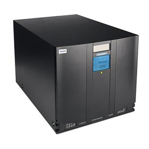
This instruction describes installing your PowerLoader. It includes:
•
Unpacking and Setting Up
•
Unparking & Parking the Shuttle
•
Setting Up the Desktop Model
•
Installing the PowerLoader
•
Interface Description & Cable Specifications
•
Connecting to the Host
•
Connecting to the Power Source
•
Rack Mount Installation
•
Configuration
127(
7KHVKXWWOHDVVHPEO\PRYHVWRWKHSDUNSRVLWLRQEULQJLQJ
WKHWKUHDGHGKROHLQWRDOLJQPHQW
2) Turn off the unit and remove all power.
3) If necessary, reposition the unit for easier access to the back panel..
4) Push in the spring-loaded lockdown screw on the back of the unite and turn it
clockwise..
5) Release the clip, allowing it to fit into the center of the leadscrew bearing.
6+,3 581
Visually inspect the shipping containers and notify your carrier immediately of any
damage. Verify the contents against the packing list. If parts are missing or the
equipment is damaged, notify your representative. Always save the containers and
packing materials for any future reshipment.
To set up the PowerLoader, do the following:
•
Follow the directions in the shipping container to unpack the PowerLoader.
•
Save the packing materials in case you need to return the unit for repairs.
•
You do not have to assemble anything.
Place the PowerLoader on a stable horizontal surface with at least a 2-inch clearance
behind the chassis to allow sufficient cooling air to flow freely from the fan, or mount
your unit in an equipment rack using the Rack Mount Installation section found in the
User and Installation Manual or Rack Mount Quick Install card.
127(
<RXPXVWXQSDUNWKHVKXWWOHEHIRUHLQVWDOODWLRQDQG
SDUNWKHVKXWWOHEHIRUHVKLSSLQJ
5HOHDVLQJWKH/RFNGRZQ0HFKDQLVP8QSDUNLQJWKH6KXWWOH
1) Make sure the power cord is disconnected from line power.
2) Release the lockdown mechanism on the PowerLoader™, using the Lockdown
Screw on the back (lower right) of the unit.
3) Turn the spring-loaded lockdown screw on the back counter-clockwise until the
lockdown mechanism releases from the shuttle.
4) Turn the Power “ON” and begin operations
/RFNLQJWKH/RFNGRZQ0HFKDQLVP3DUNLQJWKH6KXWWOH
1) Park the shuttle assembly:
a. From the Main Menu, select Maintenance Menu / Park.
8QSDUNLQJ3DUNLQJWKH6KXWWOH
,QVWUXFWLRQ&RQWHQWV 8QSDFNLQJWKH8QLW
,QVWDOOLQJWKH3RZHU/RDGHU
4) Fasten each of the mounting brackets to the front of the rear rail of the rack
using two standard 10-32 screws and one nut plate.
5) Tighten the screws installed in step 2.
6) If they are not already locked, pull the intermediate slides toward the front
(out of the rack) so that they lock in the extended position.
127(
7KHQH[WVWHSVKRXOGEHSHUIRUPHGE\WZRSHRSOH
7) Install the Library unit into the rack:
a. In front of the rack, lift the module to its installed height.
b. Engage the inner slides mounted on the module with the
intermediate slides protruding from the rack
c. Slide the module toward the rack until the inner slide’s lock
engages the intermediate slides.
d. Depress the lock tab andcontinueuntil the lock tab engagesin
the locking hole shown in the figure below. This leaves the
entire module protruding from the rack, locked in position,
supported by slides.
/RFNLQJ7D
6HWWLQJ8SWKH'HVNWRS0RGHO
The PowerLoader™desktop model requires no mechanical assembly for
mounting Place the unit on a desk, table, server top, or other stable,
horizontal surface. Make sure the cooling grilles at the rear of the unit are
not obstructed. Allow two inches of clearance behind the rear panel.
6HWWLQJ8SWKH5DFN0RXQW0RGHO
To convert a tabletop PowerLoader™to a rack mount model, order the
Rackmount Conversion Kit (Part Number 106070-001).
If your PowerLoader™is already rack-mount configured, See “Installing
Rack Mount Model”.
,QVWDOOLQJ5DFN0RXQW0RGHO
With the inner rack slides attached to the LibraryPro™unit and the
intermediate/outer slides separated from the inner slides, you can install
the outer rack slides in the rack.
1) Locate the screw holes in the front and rear rails of the cabinet or equipment
rack where the drive is to be installed.
2) Loosely assemble a mounting bracket to each outer slide, using two 10-32
screws and a nut-plate for each. Select slots in the mounting brackets so the
length of the assembly equals the distance between the front and rear rails of
the rack.
3) Fasten each outer slide behind the front rail of the rack using two 10-32 low-
profile screws and one nut plate.
8) Press inward (toward the module) on each of the inner slide locks to permit
the intermediate slides to move toward the rack.
9) Slide the module in and out several times as shown in Figure 2–10, ensuring
that the inner and outer slide locks engage, and that the module does not
bind against the slides.If they are not already locked, pull the intermediate
slides toward the front (out of the rack) so that they lock in the extended
position.
10) If binding or misalignment with other rack devices occurs, loosen the four
screws that secure the slides to the front rails and the four screws that secure
the slides to the rear rails and realign the module. Retighten the screws.
11) If necessary, repeat steps 9 and 10 until the module does not bind against the
slides.
12) Install two clip nuts on each front rail at the height of the front panel
mounting screws (thumbscrews).
,QVWDOOLQJWKH3RZHU/RDGHUFRQWLQXHG
13) Slide the module into the rack as shown in Figure 2–11, and tighten the
thumbscrews..
Module in Rack
127(
<RXDUHQRZUHDG\WRFRQQHFWSRZHUDQG
LQWHUIDFHFDEOLQJDQGFRQILJXUHWKH/LEUDU\3URPRGXOH
IRUXVH
$WWDFKWKH$&3RZHU&RUG
1) Connect a standard grounding AC cord to the connector on the
LibraryPro™. The connector is an IEC-compatible connector on the rear
panel.
2) Connect the other end to a reliably grounded AC outlet or rack power outlet.
127(
7RPDLQWDLQVDIHW\FRPSOLDQFHXVHDQDSSURYHG
SRZHUFRUG
•
U.S.UL Listed
•
Canada CSA certified
•
Europe Harmonized marked <HAR> or nationally certifie
•
Impedance match with cable terminators that meet current SCS
I
specifications
•
ICharacteristic impedance between 72 and 96 ohms for single-
ended and between 115 and 160 ohms for differential
•
34-pair twisted-pair
•
Each end of a twisted pair ground connected to chassis ground
•
Internal cable lengths of 22 inches for Drive 1 and Robot and 15
inches for Drive 2
•
Cables of different impedances should not be used together.
Additional specifications to assure the highest SCSI performance can be
found in the current version of ANSI X3.131.
127(
7KLVHTXLSPHQWKDVEHHQWHVWHGIRUHOHFWURPDJQHWLF
HPLVVLRQVDQGLPPXQLW\XVLQJJRRGTXDOLW\VKLHOGHGFDEOHV,I
\RXXVHXQVKLHOGHGRUSRRUTXDOLW\FDEOHVRURWKHUZLVHYDU\
IURPJRRGSUDFWLFH\RXPD\QRWFRPSO\ZLWKQDWLRQDODQG
LQWHUQDWLRQDOUXOHV
&RQILJXULQJWKH3RZHU/RDGHU
The LibraryPro™is designed with many configuration options, each
offering multiple settings to support a variety of applications and
platforms. The setting of each option is stored in non-volatile memory in
the module. For most applications, you do not have to change the factor
y
default settings. If you need to change the configuration, go on to the ne
x
section. If you are uncertain whether you need to change a setting, cont
a
your Technical Support representative.
To change settings, use the Control Panel. For an overview of how the
Control Panel works, and a description of the functions of the buttons,
indicators and display, refer to Entering the Menu Mode, Exiting the Me
n
Mode, and Navigating through the Menu Structure in the PowerLoader
User and Installation Manual.
You can change the settings using the procedure in How to Customize
Configuration later in this chapter. Consult your host computer and
software documentation to determine which settings you might have to
change.
$WWDFKLQJ&D OHV7R6&6,&RQQHFWRUV
Each drive is wired to an independent bus, with a pair of SCSI connectors.
Drive 1 shares a SCSI bus with the PowerLoader™'s robotics. To fully use
the bus bandwidth, connect all the SCSI buses together as shown Figure 2–
44. The insets in show how to connect the SCSI cable, the jumper cables and
the terminator for one or two-drive units.
Connectors, SCSI Terminator & Cable
Each of the drives in the PowerLoader™and the robotics is a separate SCSI
device. When any two or more devices are connected to the same SCSI bus,
each separate SCSI device must be assigned a unique SCSI address. For
information on assigning SCSI addresses, see the Configuration section.
To connect a PowerLoader™to a host computer, the host must have at least
one Wide SCSI controller and the appropriate driver software. The controller
must be LVD/SE or differential, as required to match the module in 34-pair
twisted-pair.
,QWHUIDFH&D OH6SHFLILFDWLRQV
•
PowerLoader
™is a high-performance system. To avoid degradation
of performance, use the highest-quality interface cables from a
reputable manufacturer of computer cables. All SCSI cables used
with the unit should meet the following requirements:
•
Shielded or double-shielded, as required to meet EMI specifications
6&6,
+RVW&DEOH
6&6,
-XPSHU&DEOH
6&6,
7HUPLQDWRU
$&3RZHU&RUG
'LDJQRVWLF
([SDQVLRQ3RUW
0RWRU
6&6,
-XPSHU
&DEOH
6&6,
+RVW
&DEOH
6&6,
+RV W
&DEOH
7HUPLQDWRU 7HUPLQDWR
U
'5,9(6'5,9(
'59/,%
'59
*HWWLQJ+HOS
You can get support via the Internet at
www.overlandstorage.com, or call
Tech Support at 800 729-8725 Option 5
©2003 Overland Storage, Inc.
(Jan 2003)
Part Number 104281-101 Rev A
,QVWDOODWLRQ,QVWUXFWLRQ
&RQILJXULQJWKH3RZHU/RDGHU
The LibraryPro™is designed with many configuration options, each
offering multiple settings to support a variety of applications and
platforms. The setting of each option is stored in non-volatile memory in
the module. For most applications, you do not have to change the factory
default settings. If you need to change the configuration, go on to the next
section. If you are uncertain whether you need to change a setting, contact
your Technical Support representative.
To change settings, use the Control Panel. For an overview of how the
Control Panel works, and a description of the functions of the buttons,
indicators and display, refer to Entering the Menu Mode, Exiting the Menu
Mode, and Navigating through the Menu Structure found in Chapter 3 of
the PowerLoader User & Installation manual.
1) To change the DRV1 Bus ID, scroll to DRV1 Bus ID and press
Enter
.
2) From line 4, scroll through the options and press Enter to select the number
option you want.
3) Press the
Escape
button several times to return to the Set SCSI Options
submenu.
4) Repeat this procedure for each configuration option you want to change.
127(
)RUFRPSOHWHGHVFULSWLRQVRI&RQILJXUDWLRQ2SWLRQV
VHHWKH8VHUDQG,QVWDOODWLRQ0DQXDO31
&RQILJXUDWLRQ([DPSOH6HWWLQJWKH6&6,,'
1) Turn the LibraryPro™on and wait until the Power-On Self Test
terminates and the default screen displays. You can toggle between the
Primary and Secondary Default Screens with the
p
and
q
buttons.
Primary Default Screen
Loader Idle
Drv1: No Tape
Drv2: Unloaded
i
127(
7DNHDPRPHQWWRORRNFORVHO\DWWKHVXEPHQX1RWH
WKDWWKH
u
RQWKHGLVSOD\LVQH[WWROLQHDQGWKDWOLQHLV
LQGHQWHGLQGLFDWLQJDWZRWLHUHGPHQX7KH
p
DQG
q

EXWWRQVZRUNRQWZROHYHOVLQWKLVNLQGRIPHQXZKLFKLV
W\SLFDORIPDQ\VXEPHQXVRIWKH&RQILJXUH0HQX7KHILUVW
OHYHOLVDVIROORZV,I\RXSUHVVWKH
q
EXWWRQWKH
u
PRYHVWR
OLQH,I\RXSUHVVWKH
p
EXWWRQWKH
u
PRYHVEDFNWROLQH
If you press the
Enter
button while the
u
is next to line 1 (or line 3), the
p
and
q
buttons operate on the second level. You can tell because the
u
moves next to line 2 (or line 4), and a
✴
displays at the end of line 4,
indicating that there is a list of settings that can be scrolled using the
p
and
q
buttons.
The
$
at the end of line 4 means that there are other options that can be
displayed by scrolling, using the
q
button repeatedly.
5)
Suppose you want to set the Drive 1 bus IDto 3. With the
u
next to line 1, press the
q
buttonuntil the displayscrolls as
shown in the following screen:
SCSI Options Submenu
6Withthe
u
next to line 3, press the
Enter
button. The
u
moves to line 4 and
the
$
remains at the end of line 4, and a
#
displays at the end of line 1. Use the
p
and
q
buttons to scroll line 4 to display the possible settings. Scroll up so
that 3 is displayed and press the
Enter
button to save the new selection. An
✴
displays to the left of the 3 indicating it as the current selection.
7) Press the
Escape
button repeatedly until the submenu reappears.
8) Repeat this procedure for each configuration option you want to change
uLibrary Bus ID:
✴6
Drive 1 Bus ID:
✴4
#
Secondary Default Screen
2) At the Default Screen, press the Enter button. The screen displays the Main
Menu:
Main Menu
3) Press the
q
button three times to scroll to the Configure Menu, and press
Enter
. The screen displays the Configure submenu:
Configure Submenu
4) To select a configuration option, press the
p
or
q
button on the control panel
until the
u
displays next to the option you want to change. The first two
choices on this menu, SCSI Options and Library Options, are actually
categories of options. In this case, choose SCSI Options. Press the Enter button
to display the options for that category. The submenu displays:
SCSI Options Submenu
Ready
1
u
_ _ _ _ _ _ _ _ _
t
10
11
u
_ _ _ _ _ _ _
t
199
u
Load/Unload
Remove Magazine
Maintenance Menu
Configure Menu $
u
SCSI Options
Library Options
Barcode Options
Set Base Element
#
u
Library Parity:
✴Enabled
Library Bus ID:
✴6$
&DUWULGJHDQG0DJD]LQH/RDGLQJ
,QVWDOOLQJWKH3RZHU/RDGHUFRQWLQXHG
,QVHUWLQJDQG5HPRYLQJ&DUWULGJHV
You must remove the tape magazine from the module in order to insert or
remove cartridges. When inserting cartridges, be sure that the slot you
intend to use is not already reserved in the system map for a cartridge in a
drive. The best way to avoid conflicts is to unload the drive, either through
your host computer software, or by using the Load/Unload command on the
Main Menu, described later in this chapter.
To insert or remove the magazine, make sure of the following:
•
The Control Panel is unlocked
•
The host computer must allow removal of the magazine using the
SCSI Prevent/Allow Medium Removal command. To release the lock,
exit the host software. If host computer failure prevents the host from
releasing the lock, cycle power to the PowerLoader .
If you are still unable to open the magazine door, see “Emergency Magazine
Removal”.
5HPRYLQJWKH0DJD]LQH
Whenever the magazine door is closed it is locked in place to prevent
tampering or accidental removal. To remove the magazine, enter the Menu
Mode by pressing the Enter button at the Default Screen. At the Main Menu,
select Unlock Door and press the Enter button. The magazine door swings
open
.
LXL-0027a
(PHUJHQF\0DJD]LQH5HPRYDO
If a fault occurs that prevents removal of the magazine, turn the power off for
30 seconds. Power up while continuously pressing the button. Continue to hold
the button until all of the indicators on the Control Panel light, then go out.
The door will now swing open. Release the button.
,QVHUWLQJD0DJD]LQHLQWRWKH8QLW
If the magazine door on the front of the module is closed and locked, openit, as
follows. Access the Menu Mode by pressing the Enter button at the Default
Screen. At the Main Menu, select Unlock Doorand press the Enter button. The
magazine door swings open. Slide the magazine through the door opening, with
the cartridges protruding from the left. When the magazine is fully inserted,
push the door closed until it locks.
,QVHUWLQJ&DUWULGJHVLQWRWKH0DJD]LQH
Insertcartridges so that the label end withthe write protect switchis outward,
with the write protect switch toward the bottom of the magazine. After you
insert the desired cartridges into the magazine, position the magazine so the
cartridges protrude to the left, and the magazine handle is toward you. Insert
the magazine into the PowerLoader with that orientation.
.
LXL-0026d
Write Protect
Switch
Label
Slot 1
Slot 1

Other manuals for PowerLoader

2

Other Overland Storage Storage manuals

Overland Storage NEO XL Series User manual

Overland Storage

Overland Storage NEO XL Series User manual

Overland Storage SnapServer XSD 40 User manual

Overland Storage

Overland Storage SnapServer XSD 40 User manual

Overland Storage NEO 8000E User manual

Overland Storage

Overland Storage NEO 8000E User manual

Overland Storage NEO 8000 User manual

Overland Storage

Overland Storage NEO 8000 User manual

Overland Storage REO 4600 User manual

Overland Storage

Overland Storage REO 4600 User manual

Overland Storage NEO 2000e User manual

Overland Storage

Overland Storage NEO 2000e User manual

Overland Storage PowerLoaders AIT-2 Guide

Overland Storage

Overland Storage PowerLoaders AIT-2 Guide

Overland Storage SnapServer User manual

Overland Storage

Overland Storage SnapServer User manual

Overland Storage NEO 8000 User manual

Overland Storage

Overland Storage NEO 8000 User manual

Overland Storage NEO Series User manual

Overland Storage

Overland Storage NEO Series User manual

Overland Storage NEO 8000 User manual

Overland Storage

Overland Storage NEO 8000 User manual

Overland Storage NEO 8000E User manual

Overland Storage

Overland Storage NEO 8000E User manual

Overland Storage NEOs T24 User manual

Overland Storage

Overland Storage NEOs T24 User manual

Overland Storage NEO XL Series User manual

Overland Storage

Overland Storage NEO XL Series User manual

Overland Storage NEO 400S User manual

Overland Storage

Overland Storage NEO 400S User manual

Overland Storage SnapServer DX1 User manual

Overland Storage

Overland Storage SnapServer DX1 User manual

Overland Storage NEO XL Series User manual

Overland Storage

Overland Storage NEO XL Series User manual

Overland Storage SnapScale X4 Node Guide

Overland Storage

Overland Storage SnapScale X4 Node Guide

Overland Storage SnapServer XSR 120 User manual

Overland Storage

Overland Storage SnapServer XSR 120 User manual

Overland Storage SnapServer XSD 40 User manual

Overland Storage

Overland Storage SnapServer XSD 40 User manual

Overland Storage SnapServer XSD 40 User manual

Overland Storage

Overland Storage SnapServer XSD 40 User manual

Overland Storage REO 1000 User manual

Overland Storage

Overland Storage REO 1000 User manual

Overland Storage SnapServer Service manual

Overland Storage

Overland Storage SnapServer Service manual

Overland Storage NEO S-Series User manual

Overland Storage

Overland Storage NEO S-Series User manual

Popular Storage manuals by other brands

Yamaha CDR400tx user guide

Yamaha

Yamaha CDR400tx user guide

Sony MSX-M1GN operating instructions

Sony

Sony MSX-M1GN operating instructions

Asus VC65-C Series installation guide

Asus

Asus VC65-C Series installation guide

Viavi GigaStor G4-60G-040-1152T Hardware installation

Viavi

Viavi GigaStor G4-60G-040-1152T Hardware installation

GAMERON 64 MB MEMORY CARD FOR WII manual

GAMERON

GAMERON 64 MB MEMORY CARD FOR WII manual

OpenEye OE-GRANITE3U user manual

OpenEye

OpenEye OE-GRANITE3U user manual

Kingston Technology DataTraveler Bolt Duo user manual

Kingston Technology

Kingston Technology DataTraveler Bolt Duo user manual

ASUSTOR AS6510T installation guide

ASUSTOR

ASUSTOR AS6510T installation guide

FAST LTA Silent Cubes quick start

FAST LTA

FAST LTA Silent Cubes quick start

NETGEAR SC101 - Storage Central NAS Server Revised Troubleshooting Guide

NETGEAR

NETGEAR SC101 - Storage Central NAS Server Revised Troubleshooting Guide

NetApp AFF A320 manual

NetApp

NetApp AFF A320 manual

OWC Mercury Rack Pro mini-SAS User guide & owners manual

OWC

OWC Mercury Rack Pro mini-SAS User guide & owners manual

Cisco Memory Card MEMCUE-256D= installation guide

Cisco

Cisco Memory Card MEMCUE-256D= installation guide

Audavi Ultra Wide SCSI HardTape Bay quick start guide

Audavi

Audavi Ultra Wide SCSI HardTape Bay quick start guide

HighPoint NA381TB3 user manual

HighPoint

HighPoint NA381TB3 user manual

morse 82A-SS Operator's manual

morse

morse 82A-SS Operator's manual

FeinTech 251480 user manual

FeinTech

FeinTech 251480 user manual

Hitachi Virtual Storage Platform G200 Technical reference

Hitachi

Hitachi Virtual Storage Platform G200 Technical reference

manuals.online logo
manuals.online logoBrands
  • About & Mission
  • Contact us
  • Privacy Policy
  • Terms and Conditions

Copyright 2025 Manuals.Online. All Rights Reserved.