MAN-15112
MARXQS 1021 R1
1. Unplug all cables from the rear of the computer.
2. Open the PC enclosure to gain access to the expansion slots.
3. Locate a suitable PCIe slot, x4, x8 x16 PCIe recommended for USB3 and x8
and x16 PCIe recommended for CXP (note that x1 slots may be shared with
other devices resulting in reduced system performance).
If you are unsure which slot is correct, please consult the PC user manual.
4. Remove the ller bracket corresponding to the slot you intend to use.
5. Remove the controller card carefully from its protective ESD packaging and
insert the card connector fully into the expansion slot.
6. Ensure the card’s mounting bracket is ush with any other mounting or ller
brackets to either side of it, then secure the controller card in place.
7. Replace the computer cover and secure with mounting screws if applicable.
8. Reconnect any accessories you were using previously.
Install the USB 3.0 or CoaXPress PCIe Card
Ensure your PC is powered o.
Ensure anti-static precautions and use the anti-static strap provided to prevent
potential damage. Keep all screws safe.
Notes:
• Use only the cables supplied by Andor.
• Do not connect any other device to the cards as this may interfere with
normal camera operation or performance (USB only).
• Camera operation with PCIe cards not supplied by Andor cannot be guaranteed.
• Windows 8 and 10 will install their own driver that works with the Startech card.
• When using a CoaXPress connection, please ensure sleep mode functions of the PC are deactivated.
Secure the card
to the PC
USB 3.0
Connection
Unused filler brackets
Gently press the
card into the slot
PCIe 2.0 Slot
x4 recommended
Unused filler brackets
Gently press the
card into the slot
x8 PCIe
2.0 Slot
CoaXPress
Connection
to the PC
Ensure you run Marana-X using either the USB3 or CoaXPress connection NOT both.
Checking & Setting BIOS options (only when using CXP on PCs not supplied by Andor)
Enter the BIOS menu when starting PC. For Dell workstations, press F12 at start-up and select System Setup in the
One Time Boot Menu. For Dell workstations 3 options in the Performance menu of the BIOS need to be checked/
set:
• C-States Control – Disable C-States.
• Intel Speed-step – Disable Speed-step.
• Memory Node Interleaving – Set from NUMA to SMP. Note: This option is only available on larger workstations
with 2 physical processors and may have a dierent name - ensure that NUMA is disabled.
Contamination & Damage
When not in use, the sensor chamber should be covered and sealed. Due to the exposed nature of the sensor, extreme
care should be taken with the camera, as damage can easily occur through mishandling or by contamination. If the
sensor becomes contaminated, due to accident or misuse, please contact Andor immediately for advice on cleaning.
Vacuum Operations
Ensure that the vacuum environment to which the camera is tted is free of water vapour and other contaminants. Care
should also be taken to control pressure change, as sudden pressure changes can potentially cause damage to the
sensor assembly.
Cooling Guidelines
Condensation: It is strongly advised that the camera should not be used in a condensing atmosphere. If used in a
condensing atmosphere, the sensor MUST be protected and the use of a cold nger is strongly recommended.
Best Practice Guidelines
!
Troubleshoot
Camera buzzer does not sound on start-up
• The camera buzzer should be audible momentarily (a long beep) when the camera is switched to ON.
• If this does not occur, ensure that power is connected to the camera and the ON/OFF switch is set to ON.
Camera is not recognized by PC
• Ensure camera is switched to ON (The camera must be powered up - with double beep, before the software is
initiated).
• Check that the camera cable(s) are securely and correctly connected between the camera and the PCIe card in
the PC (as described in section 4).
• Check that the PCIe card and drivers have been installed properly (Devices and printers) in Windows, Control
Panel. The camera will show under the Devices list.
Please see section 6.2 of the Hardware Guide for further information on Troubleshooting.
Online access to technical documentation is available at: andor.oxinst.com/downloads
?
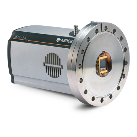
1. Use the DN100CF (ConFlat) 6”O.D. ange to mount the camera to a mating ange
with xed with blind threaded holes. The mating ange should have through holes
with adequate clearance for the mounting bolts. Please see section 3.2 of the
Hardware Guide for further information on camera mounting.
2. Connect the cooling system (if using liquid cooling):
• The cooling system must be connected via its 2 coolant pipes and running before
the camera is switched on.
• Ensure that the camera is operating within the environmental conditions stated in the hardware guide.
• Coolant temperature: should be no greater than 16°C to achieve max cooling.
• Coolant must be above the dew point of the ambient environment to prevent condensation from occurring.
3. Insert the 15 V DC power cable into the power connector at the rear of
the camera, ensure the orientation is correct. NEVER forcibly insert the
connector.
4. Connect the appropriate supplied cable between the connector on the
camera and the corresponding slot on the PCIe card (USB3 or CXP).
5. For USB3 - if required, connect the I/O expander cable to the I/O 15
way D type connector.
6. For CXP - if using an external trigger source, connect trigger cable to
SMB connector on the mounting bracket of the CoaXPress card or
directly to the camera if using the D-type connector.
7. Switch the camera ON using the ON/OFF switch. You should hear an
audible conrmation (a long beep, followed by two short beeps).
8. Turn ON the PC.
9. Start your software. Check the acquisition settings and adjust as
required. Start aquiring data.
Connect the Camera and Switch it on
Ensure that the Camera ON/OFF switch is in the OFF position AND your PC is switched OFF.
It may take 10-15 minutes to reach target cooling temperature depending on camera
cooling/environmental parameters.
Power and Signal Connections
Power
Connector
USB 3.0
Connection
On/O
Switch
External I/O
Water Connectors compatible with supplied hose
inserts - suitable for 6 mm Bore soft PVC hose (x2)
CXP
connector
Note: CoaXPress functionality only available on
CoaXPress variants.
5
Expanded view of mounting
components
4
