Ozito CMS-1621U User manual

CMS-1621U
Art.-Nr.: 43.002.99 I.-Nr.: 11039
7
GB Original operating instructions
Crosscut and miter saw
Anl_CMS_1621_U_SPK7.indb 1Anl_CMS_1621_U_SPK7.indb 1 04.11.2019 06:38:3204.11.2019 06:38:32

- 2 -
1
2
20 9
7
4
14
3
20
14
8 22 17
13
20
19
21 3
21
10
11 12
5
6
c
d
20
16 15
23
Anl_CMS_1621_U_SPK7.indb 2Anl_CMS_1621_U_SPK7.indb 2 04.11.2019 06:38:5704.11.2019 06:38:57

- 3 -
4 5
6 7
8 9
32
18
13
29
4
czf
d
31
8 a 5
7
16
28 12 19
10
8
5
28
Anl_CMS_1621_U_SPK7.indb 3Anl_CMS_1621_U_SPK7.indb 3 04.11.2019 06:39:0004.11.2019 06:39:00

- 4 -
10 11
12 13
19
5
7
8b
30
Anl_CMS_1621_U_SPK7.indb 4Anl_CMS_1621_U_SPK7.indb 4 04.11.2019 06:39:0704.11.2019 06:39:07

GB
- 5 -
Table of contents
1. Safety regulations
2. Layout and items supplied
3. Proper use
4. Technical data
5. Before starting the equipment
6. Operation
7. Replacing the power cable
8. Cleaning, maintenance and ordering of spare parts
9. Disposal and recycling
10. Storage
Anl_CMS_1621_U_SPK7.indb 5Anl_CMS_1621_U_SPK7.indb 5 04.11.2019 06:39:1004.11.2019 06:39:10

GB
- 6 -
Danger! - Read the operating instructions to reduce the risk of injury
Caution! Wear ear-muffs. The impact of noise can cause damage to hearing.
Caution! Wear safety goggles. Sparks generated during working or splinters, chips and dust emitted
by the device can cause loss of sight.
Caution! Wear a breathing mask. Dust which is injurious to health can be generated when working on
wood and other materials. Never use the device to work on any materials containing asbestos!
Caution! Risk of injury! Do not reach into the running saw blade.
Anl_CMS_1621_U_SPK7.indb 6Anl_CMS_1621_U_SPK7.indb 6 04.11.2019 06:39:1004.11.2019 06:39:10

GB
- 7 -
Danger!
When using the equipment, a few safety pre-
cautions must be observed to avoid injuries and
damage. Please read the complete operating
instructions and safety regulations with due care.
Keep this manual in a safe place, so that the in-
formation is available at all times. If you give the
equipment to any other person, hand over these
operating instructions and safety regulations as
well.We cannot accept any liability for damage
or accidents which arise due to a failure to follow
these instructions and the safety instructions.
1. Safety regulations
The corresponding safety information can be
found in the enclosed booklet.
Warning!
Read all the safety information, instructions,
illustrations and technical data provided on
or with this power tool. Failure to adhere to the
following instructions may result in electric shock,
fire and/or serious injury.
Keep all the safety information and instruc-
tions in a safe place for future use.
2. Layout and items supplied
2.1 Layout (Fig. 1/2)
1. Release lever
2. Handle
3. ON/OFF switch
4. Machine head
5. Saw blade
6. Movable blade guard
7. Stop rail
8. Turntable
9. Stationary base plate
10. Knurled screw
11. Pointer
12. Tightening screw
13. Saw shaft lockt
14. Debris bag
15. Scale
16. Safety pin
17. Scale (turntable)
18. Setting screw 0°
19. Setting screw 45°
20. Workpiece support
21. Clamping device
22.Table insert
23. Movable stop, dependent on table angle
2.2 Items supplied
Please check that the article is complete as
specified in the scope of delivery. If parts are
missing, please contact our service center or the
sales outlet where you made your purchase at
the latest within 5 working days after purchasing
the product and upon presentation of a valid bill
of purchase. Also, refer to the warranty table in
the service information at the end of the operating
instructions.
• Open the packaging and take out the equip-
ment with care.
• Remove the packaging material and any
packaging and/or transportation braces (if
available).
• Check to see if all items are supplied.
• Inspect the equipment and accessories for
transport damage.
• If possible, please keep the packaging until
the end of the guarantee period.
Danger!
The equipment and packaging material are
not toys. Do not let children play with plastic
bags, foils or small parts. There is a danger of
swallowing or suffocating!
• Crosscut and miter saw
• Carbide-tipped saw blade
• Hexagon key (c,d)
• Sawdust bag (14)
• Workpiece support (20)
• Clamping device (21)
• Original operating instructions
• Safety instructions
3. Proper use
The crosscut and miter saw is designed for cross-
cutting wood and wood-type materials which are
appropriate for the machine’s size.The saw is not
designed for cutting firewood.
The equipment is to be used only for its prescri-
bed purpose. Any other use is deemed to be a
case of misuse.The user / operator and not the
manufacturer will be liable for any damage or inju-
ries of any kind caused as a result of this.
Please note that our equipment has not been de-
signed for use in commercial, trade or industrial
applications. Our warranty will be voided if the
machine is used in commercial, trade or industrial
Anl_CMS_1621_U_SPK7.indb 7Anl_CMS_1621_U_SPK7.indb 7 04.11.2019 06:39:1104.11.2019 06:39:11

GB
- 8 -
businesses or for equivalent purposes.
The equipment is to be operated only with suita-
ble saw blades. It is prohibited to use any type of
cutting-offwheel.
To use the equipment properly you must also
observe the safety information, the assembly
instructions and the operating instructions to be
found in this manual.
All persons who use and service the equipment
have to be acquainted with these operating
instructions and must be informed about the
equipment’s potential hazards. It is also imperati-
ve to observe the accident prevention regulations
in force in your area.The same applies for the
general rules of health and safety at work.
The manufacturer will not be liable for any chan-
ges made to the equipment nor for any damage
resulting from such changes. Even when the
equipment is used as prescribed it is still impos-
sible to eliminate certain residual risk factors.The
following hazards may arise in connection with
the machine’s construction and design:
• Contact with the saw blade in the uncovered
saw zone.
• Reaching into the running saw blade (cut inju-
ries).
• Kick-back of workpieces and parts of workpi-
eces.
• Saw blade fracturing.
• Catapulting of faulty carbide tips from the saw
blade.
• Damage to hearing if ear-muffs are not used
as necessary.
• Harmful emissions of wood dust when used
in closed rooms.
4. Technical data
Asynchronous motor................220-240 V~ 50 Hz
Input power ....S1 1400 Watt / S6 40% 1600 Watt
Idle speed n0......................................... 5000 rpm
Carbide saw blade.............. ø210 x ø30 x 2,8 mm
Number of teeth............................................... 48
Weight.........................................................7,1 kg
Tilting range.................................. -45° / 0° / +45°
Mitre cuts................................ 0° to 45° to the left
Sawing width at 90° ................ max. 120 x 55 mm
Sawing width at 45° .................. max. 80 x 55 mm
Sawing width at 2 x 45°
(double mitre cuts).............................80 x 32 mm
Minimum workpiece size: Only ever cut workpie-
ces which are big enough to clamp securely with
the clamping device – minimum length 160 mm.
Operating mode S6 40%: Continuous operation
with idling (cycle time 10 minutes).To ensure that
the motor does not become excessively hot it
may only be operated for 40% of the cycle at the
specified rating and must then be allowed to idle
for 60% of the cycle.
Danger!
Noise
The noise emission values were measured in
accordance with EN 62841.
LpA sound pressure level ...................... 101 dB(A)
KpA uncertainty .............................................3 dB
LWA sound power level ......................... 114 dB(A)
KWA uncertainty .............................................3 dB
Wear ear-muffs.
The impact of noise can cause damage to hea-
ring.
The stated vibration emission levels and stated
noise emission values were measured in ac-
cordance with a set of standardized criteria and
can be used to compare one power tool with
another.
The stated vibration emission levels and stated
noise emission values can also be used to make
an initial assessment of exposure.
Warning:
The vibration and noise emission levels may vary
from the level specified during actual use, depen-
ding on the way in which the power tool is used,
especially the type of workpiece it is used for.
Keep the noise emissions and vibrations to a
minimum.
• Only use appliances which are in perfect wor-
king order.
• Service and clean the appliance regularly.
• Adapt your working style to suit the appliance.
• Do not overload the appliance.
• Have the appliance serviced whenever ne-
cessary.
• Switch the appliance off when it is not in use.
Anl_CMS_1621_U_SPK7.indb 8Anl_CMS_1621_U_SPK7.indb 8 04.11.2019 06:39:1104.11.2019 06:39:11

GB
- 9 -
Caution!
Residual risks
Even if you use this electric power tool in
accordance with instructions, certain resi-
dual risks cannot be rules out. The following
hazards may arise in connection with the
equipment’s construction and layout:
1. Lung damage if no suitable protective dust
mask is used.
2. Damage to hearing if no suitable ear protec-
tion is used.
3. Health damage caused by hand-arm vib-
rations if the equipment is used over a pro-
longed period or is not properly guided and
maintained.
5. Before starting the equipment
Before you connect the equipment to the mains
supply make sure that the data on the rating plate
are identical to the mains data.
Warning!
Always pull the power plug before making
adjustments to the equipment.
5.1 General information
• The equipment must be set up where it can
stand securely, i.e. it should be bolted to a
workbench, a universal base frame or similar.
• All covers and safety devices have to be pro-
perly fitted before the equipment is switched
on.
• It must be possible for the blade to run freely.
• When working with wood that has been pro-
cessed before, watch out for foreign bodies
such as nails or screws, etc.
• Before you actuate the On/Off switch, make
sure that the saw blade is correctly fitted
and that the equipment’s moving parts run
smoothly.
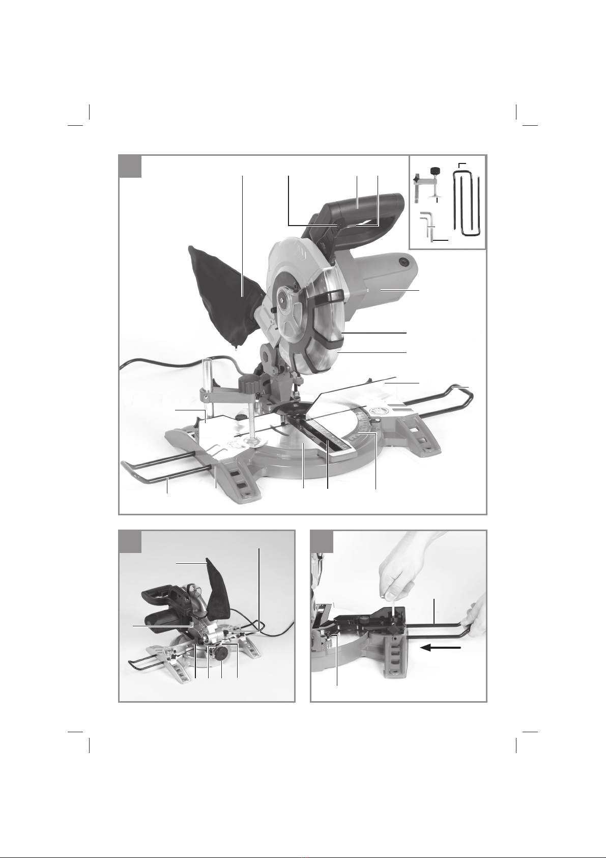
5.2 Setting up the saw (Fig. 3)
The workpiece supports must be inserted and
tightened using a hex key (C).
5.3 Adjusting the saw (Fig. 1/2)
• To adjust the turntable (8), loosen the knurled
screw (10) by approx. 2 turns, which frees the
turntable.
• The turntable has locking points at angles
of 0°, 5°, 10°, 15°, 22,5°, 30°, 35°, 40°, 45°.
Once the turntable is engaged, the setting
must be additionally secured by tightening
the knurled screw (10).
• If different angle settings are required, the
turntable (8) may be secured in position using
only the knurled screw (10).
• Lightly press the machine head (4) down
while at the same time pulling the retaining
pin (16) out from the motor mounting; this
causes the saw to move down to the lower
working position.
• Swing up the machine head (4).
• By loosening the lock screw (12), the machi-
ne head (4) can be angled to the left up to
45°.
• Check that the voltage marked on the rating
plate is the same as your mains voltage and
connect up the machine.
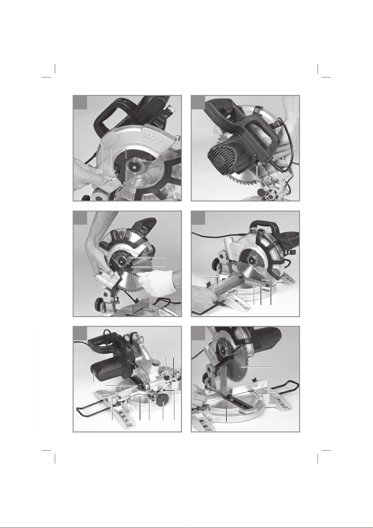
5.4 Precision adjustment of the stop rail
(Fig. 7/8)
• Lower the machine head (4) and fasten in
place with the safety pin (16).
• Fasten the turntable (8) in 0° position.
• Place the 90° stop angle (a) between the bla-
de (5) and the stop rail (7).
• Slacken the adjustment screws (28), set the
stop rail (7) to 90° in relation to the saw blade
(5) and retighten the adjustment screws (28).
5.5 Precision adjustment of the stop for 90°
cross-cuts (Fig. 8-10)
• Lower the machine head (4) and fix with the
lock pin (16).
• Slacken the tightening screw (12).
• Place the stop angle (a) between the saw bla-
de (5) and the rotary table (8).
• Slacken the counter nut (29) and adjust the
setting screw (18) until the angle between the
saw blade (5) and the rotary table (8) equals
90°.
• Re-tighten the counter nut (29) to fix the ma-
chine in this setting.
• Finally, check the position of the angle indica-
tor (11). If necessary, release the pointer with
a crosstip screwdriver, move to the 0° position
of the angle scale (15) and retighten the hol-
ding screw.
• No stop angle included.
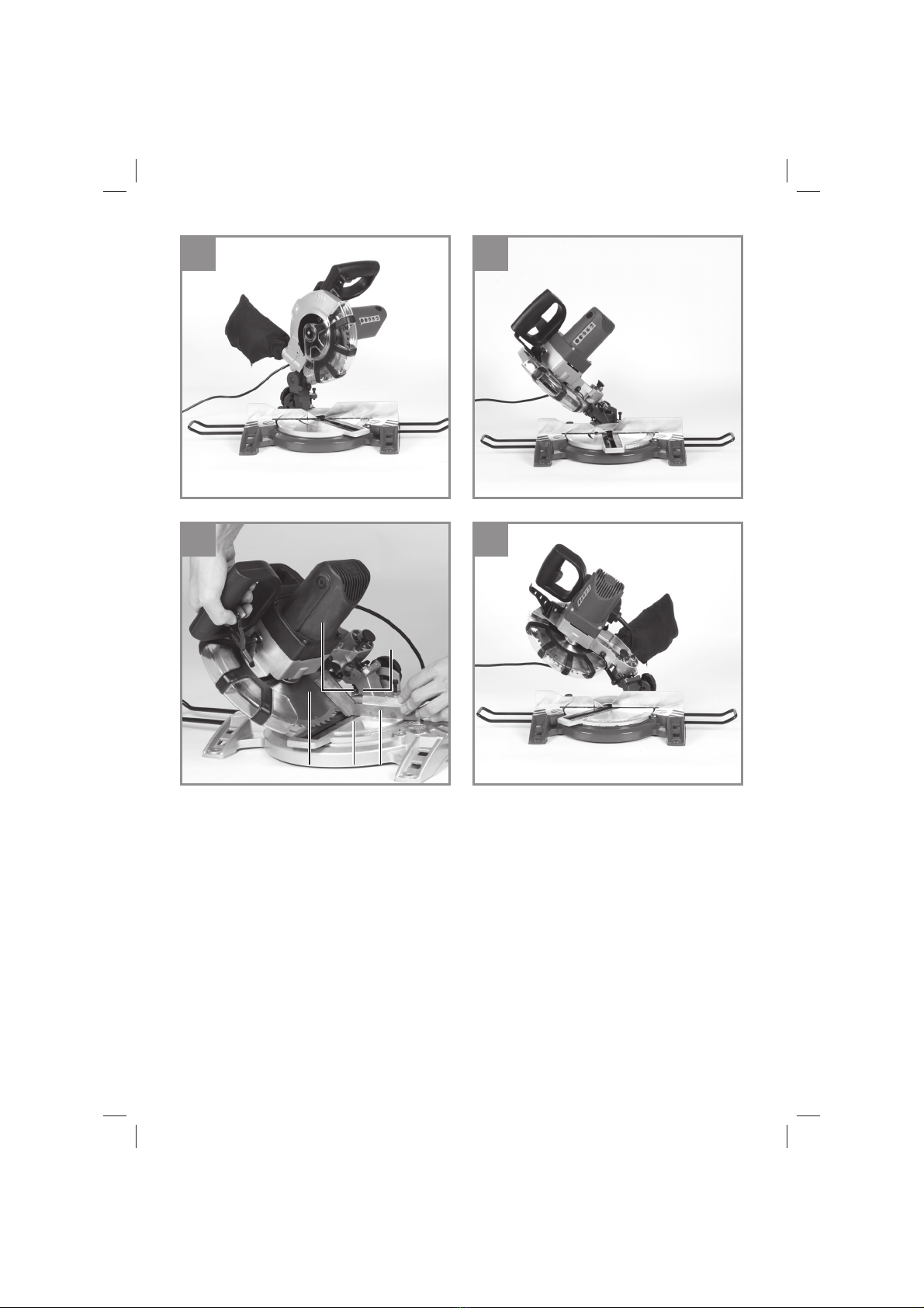
5.6 Precision adjustment of the stop for 45°
mitre cuts (Fig. 8/12)
• Lower the machine head (4) and fix with the
lock pin (16).
• Fix the rotary table (8) in 0° position.
• Undo the tightening screw (12) and use the
handle (2) to tilt the machine head (4) to the
Anl_CMS_1621_U_SPK7.indb 9Anl_CMS_1621_U_SPK7.indb 9 04.11.2019 06:39:1104.11.2019 06:39:11

GB
- 10 -
left until it coincides at 45°.
• Place the 45° stop angle (b) between the saw
blade (5) and the rotary table (8).
• Slacken the counter nut (30) and adjust the
setting screw (19) until the angle between the
saw (5) and the rotary table (8) equals exactly
45°.
• No stop angle included.
6. Operation
6.1 Crosscut 90° and turntable 0° (Fig. 1)
• Press the main switch (3) to turn on the saw.
• Important. Place the material for sawing firmly
on the machine surface, to prevent it from
moving during the sawing process.
• After switching on the saw, wait for the blade
(5) to reach its maximum speed.
• Press the release lever (1) sideways and,
using the handle (2), apply steady and light
downward pressure to move the machine
head through the workpiece.
• When the cut is completed, return the machi-
ne to its top parking position and let go of the
On/Off switch.
• Caution! A return spring causes the machine
head to rise automatically at the end of the
cut. Do not let go of the handle (2) as soon as
the cut is completed but steady the machine
head and allow it to rise slowly.
6.2 90° cross-cuts and 0°-45° rotary table
(Fig. 10)
The crosscut saw can be used to make right and
left angular cuts of 0°- 45° in relation to the stop
rail.
• Lift the machine head (4) to its top position.
• Release the turntable (8) by slackening the
locking grip (10).
• Using the handle (2), set the turntable (8) to
the desired angle, i.e. the marking on the turn-
table must coincide with the desired angular
setting (17) on the stationary base plate (9).
• Re-tighten the locking handle (10) in order to
fix the rotary table (8) in position.
• Make the cut as described in Section 6.1).
6.3 Mitre cuts 0°-45° and rotary table 0°
(Fig. 8/11)
The crosscut saw can be used to make miter cuts
of 0° - 45° in relation to the work face.
• Lift the machine head (4) to its top position.
• Fix the rotary table (8) in 0° position.
• Undo the tightening screw (12) and use the
handle (2) to tilt the machine head (4) to the
left until the pointer (11) coincides with the
required angle value (15).
• Re-tighten the locking nut (12) and make the
cut as described in Section 6.1).
6.4 Mitre cuts 0°-45° and rotary table 0°-45°
(Fig. 8/13)
The crosscut saw can be used to make miter cuts
to the left of 0°- 45° in relation to the work face
and, at the same time, 0° - 45° in relation to the
stop rail (double miter cut).
• Lift the machine head (4) to its top position.
• Release the turntable (8) by slackening the
locking grip (10).
• Adjust the rotary table (8) by its handle (2) to
the required angle (see also Section 6.2).
• Retighten the tightening screw (10) in order to
secure the turntable in place.
• Undo the tightening screw (12) and use the
handle (2) to tilt the machine head (4) to the
left until it coincides with the required angle
value (in this connection see also section
6.3).
• Screw the tightening screw (12) back down
again.
6.5 Sawdust bag (Fig. 2)
The saw is equipped with a debris bag (14) for
sawdust and chips.
The debris bag (14) can be emptied by means of
a zipper at the bottom.
6.6 Replacing the saw blade (Fig. 1-6)
• Before changing the saw blade: Remove the
power plug!
• Wear work gloves to prevent injury when
changing the saw blade.
• Swing the machine head upwards (4).
• Undo the screw (z) on the cover plate (f) of
the saw blade.
• Pull back the adjustable blade guard (6) and
at the same time turn the cover plate to achie-
ve access to the flange bolt.
• Press the saw shaft lock (13) with one hand
while positioning the hexagon key (d) on the
flange bolt (31) with the other hand.The saw
shaft lock (13) engages after no more than
one rotation.
• Now, using a little more force, slacken the
flange screw (31) in the clockwise direction.
• Turn the flange screw (31) right out and remo-
ve the external flange (32).
• Take the blade (5) off the inner flange and pull
Anl_CMS_1621_U_SPK7.indb 10Anl_CMS_1621_U_SPK7.indb 10 04.11.2019 06:39:1104.11.2019 06:39:11

GB
- 11 -
out downwards.
• Carefully clean the flange screw (31), outer
flange (32) and inner flange.
• Fit and fasten the new saw blade (5) in rever-
se order.
• Important. The cutting angle of the teeth, in
other words the direction of rotation of the
saw blade (5) must coincide with the direction
of the arrow on the housing.
• Check to make sure that all safety devices
are properly mounted and in good working
condition before you begin working with the
saw again.
• Important. Every time that you change the
saw blade, check to see that it spins freely in
the table insert (22) in both perpendicular and
45° angle settings.
• Important. The work to change and align the
saw blade (5) must be carried out correctly.
7. Replacing the power cable
Danger!
If the power cable for this equipment is damaged,
it must be replaced by the manufacturer or its
after-sales service or similarly trained personnel
to avoid danger.
8. Cleaning, maintenance and
ordering of spare parts
Danger!
Always pull out the mains power plug before star-
ting any cleaning work.
8.1 Cleaning
• Keep all safety devices, air vents and the
motor housing free of dirt and dust as far as
possible.Wipe the equipment with a clean
cloth or blow it with compressed air at low
pressure.
• We recommend that you clean the device
immediately each time you have finished
using it.
• Clean the equipment regularly with a moist
cloth and some soft soap. Do not use
cleaning agents or solvents; these could at-
tack the plastic parts of the equipment. Ensu-
re that no water can seep into the device.The
ingress of water into an electric tool increases
the risk of an electric shock.
8.2 Carbon brushes
In case of excessive sparking, have the carbon
brushes checked only by a qualified electrician.
Important! The carbon brushes should not be re-
placed by anyone but a qualified electrician.
8.3 Maintenance
• There are no parts inside the equipment
which require additional maintenance.
• Lubricate all moving parts at regular intervals.
8.4 Ordering spare parts and accessories
Please provide the following information when
ordering spare parts:
• Type of unit
• Article number of the unit
• ID number of the unit
• Spare part number of the required spare part
For our latest prices and information please go to
www.isc-gmbh.info
Tip! For good results we
recommend high-quality ac-
cessories from !
www.kwb.eu
welcome@kwb.eu
9. Disposal and recycling
The equipment is supplied in packaging to pre-
vent it from being damaged in transit.The raw
materials in this packaging can be reused or
recycled.The equipment and its accessories are
made of various types of material, such as metal
and plastic. Never place defective equipment in
your household refuse.The equipment should
be taken to a suitable collection center for proper
disposal. If you do not know the whereabouts of
such a collection point, you should ask in your
local council offices.
10. Storage
Store the equipment and accessories out of
children’s reach in a dark and dry place at above
freezing temperature.The ideal storage tempe-
rature is between 5 and 30 °C. Store the electric
tool in its original packaging.
Anl_CMS_1621_U_SPK7.indb 11Anl_CMS_1621_U_SPK7.indb 11 04.11.2019 06:39:1104.11.2019 06:39:11

GB
- 12 -
For EU countries only
Never place any electric power tools in your household refuse.
To comply with European Directive 2012/19/EC concerning old electric and electronic equipment and
its implementation in national laws, old electric power tools have to be separated from other waste and
disposed of in an environment-friendly fashion, e.g. by taking to a recycling depot.
Recycling alternative to the return request:
As an alternative to returning the equipment to the manufacturer, the owner of the electrical equipment
must make sure that the equipment is properly disposed of if he no longer wants to keep the equipment.
The old equipment can be returned to a suitable collection point that will dispose of the equipment in
accordance with the national recycling and waste disposal regulations.This does not apply to any ac-
cessories or aids without electrical components supplied with the old equipment.
The reprinting or reproduction by any other means, in whole or in part, of documentation and papers
accompanying products is permitted only with the express consent of the iSC GmbH.
Subject to technical changes
Anl_CMS_1621_U_SPK7.indb 12Anl_CMS_1621_U_SPK7.indb 12 04.11.2019 06:39:1104.11.2019 06:39:11

GB
- 13 -
Service information
We have competent service partners in all countries named on the guarantee certificate whose contact
details can also be found on the guarantee certificate. These partners will help you with all service re-
quests such as repairs, spare and wearing part orders or the purchase of consumables.
Please note that the following parts of this product are subject to normal or natural wear and that the
following parts are therefore also required for use as consumables.
Category Example
Wear parts* Carbon brushes
Consumables* Saw blade
Missing parts
* Not necessarily included in the scope of delivery!
In the effect of defects or faults, please register the problem on the internet at www.isc-gmbh.info. Ple-
ase ensure that you provide a precise description of the problem and answer the following questions in
all cases:
• Did the equipment work at all or was it defective from the beginning?
• Did you notice anything (symptom or defect) prior to the failure?
• What malfunction does the equipment have in your opinion (main symptom)?
Describe this malfunction.
Anl_CMS_1621_U_SPK7.indb 13Anl_CMS_1621_U_SPK7.indb 13 04.11.2019 06:39:1204.11.2019 06:39:12

GB
- 14 -
Warranty certificate
Dear Customer,
All of our products undergo strict quality checks to ensure that they reach you in perfect condition. In the
unlikely event that your device develops a fault, please contact our service department at the address
shown on this guarantee card.You can also contact us by telephone using the service number shown.
Please note the following terms under which guarantee claims can be made:
1. These guarantee terms apply to consumers only, i.e. natural persons intending to use this product
neither for their commercial activities nor for any other self-employed activities.These warranty
terms regulate additional warranty services, which the manufacturer mentioned below promises to
buyers of its new products in addition to their statutory rights of guarantee.Your statutory guarantee
claims are not affected by this guarantee. Our guarantee is free of charge to you.
2. The warranty services cover only defects due to material or manufacturing faults on a product which
you have bought from the manufacturer mentioned below and are limited to either the rectification of
said defects on the product or the replacement of the product, whichever we prefer.
Please note that our devices are not designed for use in commercial, trade or professional applica-
tions. A guarantee contract will not be created if the device has been used by commercial, trade or
industrial business or has been exposed to similar stresses during the guarantee period.
3. The following are not covered by our guarantee:
- Damage to the device caused by a failure to follow the assembly instructions or due to incorrect
installation, a failure to follow the operating instructions (for example connecting it to an incorrect
mains voltage or current type) or a failure to follow the maintenance and safety instructions or by ex-
posing the device to abnormal environmental conditions or by lack of care and maintenance.
- Damage to the device caused by abuse or incorrect use (for example overloading the device or the
use or unapproved tools or accessories), ingress of foreign bodies into the device (such as sand,
stones or dust, transport damage), the use of force or damage caused by external forces (for ex-
ample by dropping it).
- Damage to the device or parts of the device caused by normal or natural wear or tear or by normal
use of the device.
4. The guarantee is valid for a period of 24 months starting from the purchase date of the device. Gu-
arantee claims should be submitted before the end of the guarantee period within two weeks of the
defect being noticed. No guarantee claims will be accepted after the end of the guarantee period.
The original guarantee period remains applicable to the device even if repairs are carried out or
parts are replaced. In such cases, the work performed or parts fitted will not result in an extension
of the guarantee period, and no new guarantee will become active for the work performed or parts
fitted.This also applies if an on-site service is used.
5. To make a claim under the guarantee, please register the defective device at: www.isc-gmbh.info.
Please keep your bill of purchase or other proof of purchase for the new device. Devices that are
returned without proof of purchase or without a rating plate shall not be covered by the guarantee,
because appropriate identification will not be possible. If the defect is covered by our guarantee,
then the item in question will either be repaired immediately and returned to you or we will send you
a new replacement.
Of course, we are also happy offer a chargeable repair service for any defects which are not covered by
the scope of this guarantee or for units which are no longer covered.To take advantage of this service,
please send the device to our service address.
Also refer to the restrictions of this warranty concerning wear parts, consumables and missing parts as
set out in the service information in these operating instructions.
Anl_CMS_1621_U_SPK7.indb 14Anl_CMS_1621_U_SPK7.indb 14 04.11.2019 06:39:1204.11.2019 06:39:12

Dong/Product-ManagementAndreas Weichselgartner/General-Manager
- 15 -
Derklärt folgende Konformität gemäß EU-Richtlinie und
Normen für Artikel
GB explains the following conformity according to EU directi-
ves and norms for the following product
Fdéclare la conformité suivante selon la directive CE et les
normes concernant l’article
Idichiara la seguente conformità secondo la direttiva UE e
le norme per l’articolo
NL verklaart de volgende overeenstemming conform EU
richtlijn en normen voor het product
Edeclara la siguiente conformidad a tenor de la directiva y
normas de la UE para el artículo
Pdeclara a seguinte conformidade, de acordo com as
diretiva CE e normas para o artigo
DK attesterer følgende overensstemmelse i medfør af
EU-direktiv samt standarder for artikel
Sförklarar följande överensstämmelse enl. EU-direktiv och
standarder för artikeln
FIN vakuuttaa, että tuote täyttää EU-direktiivin ja standardien
vaatimukset
EE tõendab toote vastavust EL direktiivile ja standarditele
CZ vydává následující prohlášení o shoděpodle směrnice EU
a norem pro výrobek
SLO potrjuje sledečo skladnost s smernico EU in standardi za
izdelek
SK vydáva nasledujúce prehlásenie o zhode podľa smernice
EÚ a noriem pre výrobok
Ha cikkekhez az EU-irányvonal és Normák szerint a
következőkonformitást jelenti ki
PL deklaruje zgodność wymienionego poniżej artykułu z
następującymi normami na podstawie dyrektywy WE.
BG декларира съответното съответствие съгласно
Директива на ЕС инорми за артикул
LV paskaidro šādu atbilstību ES direktīvai un standartiem
LT apibūdina šįatitikimąEU reikalavimams ir prekės normoms
RO declarăurmătoarea conformitate conform directivei UE şi
normelor pentru articolul
GR δηλώνει την ακόλουθη συμμόρφωση σύμφωνα με την
Οδηγία ΕΚ και τα πρότυπα για το προϊόν
HR potvrđuje sljedeću usklađenost prema smjernicama EU i
normama za artikl
BIH potvrđuje sljedeću usklađenost prema smjernicama EU i
normama za artikl
RS potvrđuje sledeću usklađenost prema smernicama EZ i
normama za artikal
RUS следующим удостоверяется, что следующие продукты
соответствуют директивам инормам ЕС
UKR проголошує про зазначену нижче відповідність виробу
директивам та стандартам ЄС на виріб
MK ја изјавува следната сообрзност согласно
ЕУ-директивата инормите за артикли
TR Ürünü ile ilgili AB direktifleri ve normlarıgereğince aşağıda
açıklanan uygunluğu belirtir
Nerklærer følgende samsvar i henhold til EU-direktivet og
standarder for artikkel
IS Lýsir uppfyllingu EU-reglna og annarra staðla vöru
Mitre Saw CMS-1621U (Ozito)
2014/29/EU
2005/32/EC_2009/125/EC
2014/35/EU
2006/28/EC
X2014/30/EU
2014/32/EU
2014/53/EU
2014/68/EU
(EU)2016/426
Notified Body:
(EU)2016/425
X2011/65/EU_(EU)2015/863
X2006/42/EC
Annex IV
Notified Body:
Reg. No.:
2000/14/EC_2005/88/EC
Annex V
Annex VI
Noise: measured LWA = dB (A); guaranteed LWA = dB (A)
P = KW; L/Ø = cm
Notified Body:
2012/46/EU_(EU)2016/1628
Emission No.:
Standard references: EN 62841-1; EN 62841-3-9;
EN 55014-1; EN 55014-2; EN 61000-3-2; EN 61000-3-3
Landau/Isar, den 27.09.2019
First CE: 16 Archive-File/Record: NAPR022580
Art.-No.: 43.002.99 I.-No.: 11039 Documents registrar: Hofner Felix
Subject to change without notice Wiesenweg 22, D-94405 Landau/Isar
ISC GmbH · Eschenstraße 6 · D-94405 Landau/Isar
Anl_CMS_1621_U_SPK7.indb 15Anl_CMS_1621_U_SPK7.indb 15 04.11.2019 06:39:1204.11.2019 06:39:12

EH 10/2019 (01)
Anl_CMS_1621_U_SPK7.indb 16Anl_CMS_1621_U_SPK7.indb 16 04.11.2019 06:39:1204.11.2019 06:39:12
This manual suits for next models
1
Table of contents
Other Ozito Saw manuals

Ozito
Ozito CMS-1621 User manual

Ozito
Ozito MSW-3000U User manual

Ozito
Ozito PXCSS-165 User manual

Ozito
Ozito CSW-7000U Installation instructions

Ozito
Ozito CMS-1621 User manual

Ozito
Ozito tsb-0808 User manual

Ozito
Ozito SCMS-10STANDU User manual

Ozito
Ozito CMS-210 User manual

Ozito
Ozito PCR-3100U User manual

Ozito
Ozito CMSB-1421 User manual

Ozito
Ozito JSW-8100 User manual

Ozito
Ozito JSW-6100 User manual

Ozito
Ozito PLS-1214 User manual

Ozito
Ozito CSL-018 User manual

Ozito
Ozito ZLRSS-012 User manual

Ozito
Ozito OZMCS2000WB User manual

Ozito
Ozito RSG-491VK User manual

Ozito
Ozito RSW-5100 User manual

Ozito
Ozito PXRSS-400 User manual

Ozito
Ozito SCMS-107 User manual