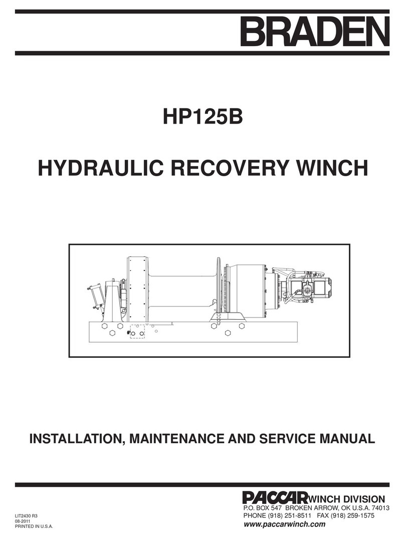
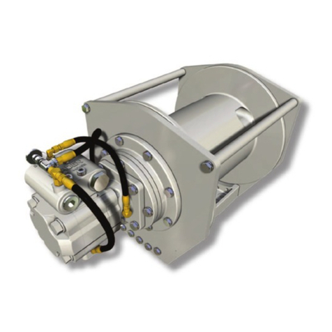
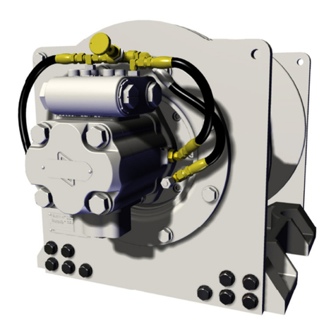
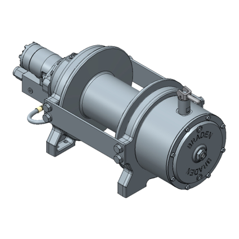
Paccar Carco H200 User manual

1
LIT2753
October 2018
Printed in USA
©2018 PACCAR Inc.
All rights reserved
H200
SERVICE MANUAL
H200 Tail Winch
Visit our Web site at www.paccarwinch.com for the most comprehensive collection of winch, hoist, and drive
information on the Internet. Most publications and specification sheets are available for downloading.
WRITE WINCH SERIAL NUMBER BELOW
}
First 2 numbers indicate
year manufactured
For serial number location see page 3

2
Table of Contents
Foreword ..................................................................................................................... 2
Model Identification ..................................................................................................... 3
Explanation of Model Number..................................................................................... 4
General Safety Recommendations ............................................................................. 4
Theory of Operation .................................................................................................... 6
Preventive Maintenance............................................................................................ 10
Specifications ............................................................................................................ 11
Recommended Planetary Gear Oil ........................................................................... 12
Wire Rope Installation ............................................................................................... 13
Troubleshooting......................................................................................................... 14
H200 Major Parts Groups Cross-section .................................................................. 19
H200 Major Parts Groups Components.................................................................... 20
Service Precautions .................................................................................................. 20
Winch Removal and Installation................................................................................ 21
Winch Disassembly ................................................................................................... 22
Primary Planet Carrier Service.................................................................................. 28
Secondary Planet Carrier Service............................................................................. 29
Third Planet Carrier Service...................................................................................... 30
Output Planet Carrier Service ................................................................................... 31
Drum Clutch Assembly Service................................................................................. 32
Brake Assembly Service ........................................................................................... 34
Brake Assembly Pressure Test................................................................................. 35
Brake Valve Service.................................................................................................. 36
Overrunning Clutch Service ...................................................................................... 38
Cable Drum Service .................................................................................................. 39
Winch Assembly........................................................................................................ 41
Brake Cylinder Lifting Fixture .................................................................................... 47
FOREWORD
Managing Waste
PACCAR Winch believes in a life-cycle approach to our products. We encourage best practices regarding “Going
Green” — making environmentally responsible decisions to “reduce, reuse, and recycle.”
• At the end of the winch’s useful life, it is highly recommended to drain and recycle any oil remaining in the equipment.
• Please use a metal recycler for winch disposal to reduce landll waste.
The U.S. Environmental Protection Agency has developed required practices, called “management standards,” for busi-
nesses that handle used oil and metal wastes. Specic guidelines are available at the EPA and API Web sites as well
as your state’s environmental agency Web site:
• https://www.epa.gov/
• http://recycleoil.org/

3
This service manual has been prepared to provide maintenance information for the CARCO H200 hydraulic winches
built for use on various crawler tractors. Depending on the specic tractor hydraulics, the winches will be congured
with either variable displacement piston motors or xed displacement vane motors. When instructions apply to only one
specic winch conguration, that designation (such as variable displacement motor only) will appear at the beginning of
the related text. If not identied in this manner, the text applies to ALL H200 winches.
Read this entire publication and retain it for future reference.
For inquiries regarding your CARCO winch or this publication, please contact the CARCO Service Department at
918-251-8511, Monday through Friday, 8:00 a.m. to 4:30 p.m. (CST).
Some illustrations in this manual may show details or attachments dierent from your winch. Some components have
been removed for illustrative purposes. Drawings in this manual represent a typical unit sold through our distribution
channels. Some winches, particularly those sold directly to original equipment manufacturers, may dier in appearance
and options.
NOTE: The hydraulic motors and selected gear ratios on CARCO H200 winches are specically congured for use on
the intended tractor. The winch may not be suitable or advisable for use on anything other than the intended tractor.
Contact the CARCO Service Department with questions regarding retrotting your winch to other tractors.
FOREWORD
Model numbers, part numbers, and serial numbers
are located on the nameplate. Always refer to the
model number, part number, and serial number
when requesting information or service parts.
There is also another stamped serial number locat-
ed near the top side of winch mounting holes.
MODEL IDENTIFICATION
Safety and informational callouts used in this manual include the following Warnings and Cautions:
CAUTION – This emblem is used to warn against
potential or unsafe practices which COULD result
in personal injury and product or property damage if
proper procedures are not followed.
WARNING – This emblem is used to warn against
hazards and unsafe practice which COULD result in
severe personal injury or death if proper procedures
are not followed.
CAUTION
!
!
!WARNING !

4
Safety for operators and ground personnel is of prime
concern. Always take the necessary precautions to
ensure the safety of others as well as yourself. To ensure
safety, the tractor and winch MUST be operated with care
and concern by the equipment operator. The operator
MUST also have a thorough knowledge of the machine’s
performance capabilities.
The following recommendations are offered as a general
safety guide. Local rules and regulations also apply.
1. Read and understand ALL warning tag information,
and become familiar with ALL controls BEFORE
operating the winch.
2. NEVER attempt to clean oil or perform maintenance
on a machine with the engine or prime mover running,
unless instructed to do so in this manual.
3. Before starting the tractor, be certain all controls
move freely and are placed in the brake-on (neutral)
position.
4. NEVER operate the winch controls unless you are
properly positioned at the operator’s station, you are
sure ALL personnel are clear of the work area AND
you are properly trained in the operation of the winch.
5. Assure that personnel who are responsible for hand
signals are clearly visible and that the signals to be
used are thoroughly understood by all involved.
6. Ground personnel should stay in view of the operator
and clear of the winch drum. DO NOT allow ground
personnel near a winch line under tension. A safe
distance of at least 1-1/2 times the length of the out-
stretched cable should be maintained.
7. Avoid sudden shock loads or attempting to jerk a load
free. This type of operation may cause heavy loads, in
excess of rated capacity, which may result in a failure
of the wire rope and/or the winch.
8. Use only GENUINE CARCO parts. Do not use parts
from other winch manufacturers on your CARCO
winch. Do not use CARCO parts on winches from
other manufacturers.
9. Use correct size ferrule for cable and pocket in winch
drum. Never use knots to attach or secure cable.
The cable anchor or ferrule pocket in the cable drum
is designed to provide a self-release in the event a
backsliding load must be released from the tractor in
an emergency. The cable anchor or ferrule alone will
NOT support rated line pull. Therefore, a minimum of
five complete wraps of cable must be maintained on
the winch drum.
NOTE: We suggest painting the last five wraps of cable
bright red to serve as a visual warning.
Recommended Operating Practices
1. Wear leather gloves when handling winch cable.
2. Operate the winch to match line speeds to job condi-
tions.
GENERAL SAFETY RECOMMENDATIONS
TO ORDER:
1. List model and serial numbers of the winch.
2. Refer to cross-section drawing (exploded view), select the component(s) needed, and note item number.
3. Find item number on parts list. Show part number, description, and quantity required on your order.
4. Refer to Parts List and show price for each component or assembly.
EXPLANATION OF MODEL NUMBER
HHydraulic motor, two-speed
200 200,000-lb. first-layer line pull
500V 500:1 gear ratio
MAXIMUM
RATING
H– 200 – 500V
MOTOR GEAR
RATIO
Failure to obey the following safety recommendations
COULD result in property damage, severe personal
injury, or death if proper procedures are not followed.
!WARNING !

5
3. Assure that personnel responsible for hand signals
are clearly visible and that the signals are thoroughly
understood by everyone.
4. Inspect winch cable, rigging, winch and tractor at the
beginning of each work shift. Defects should be cor-
rected immediately.
5. Position tractor for straightest line of pull to reduce
wear on winch cable and ensure even spooling.
6. When winding winch cable on the winch drum, never
attempt to maintain tension by allowing winch cable
to slip through hands. Always use hand-over-hand
technique, being careful to keep hands and clothing
away from winch drum and fairlead rollers.
7. Be sure of tractor ground stability before winching in
a load.
8. Store unused chokers, slings, and rigging in a neat
and orderly fashion to prevent damage to equipment
or injury to personnel.
9. Do not operate the winch under loads that exceed the
maximum rated bare drum line pull. For excessive
loads, use a multipart line and sheave blocks. Any
attempt to exceed the capacity of one winch (such as
coupling two or more tractors together) is extremely
hazardous.
10. The factory-approved adaptions for CARCO winches
are designed and intended for use on specific mod-
els of crawler tractors. Changing winches between
trac- tors is not possible in some cases because of
differ- ences in tractor models. Some changes cannot
be approved by CARCO because of safety limitations.
Call a CARCO dealer or the CARCO factory prior to
attempting winch modifications or before mounting on
a different tractor.
11. CARCO H Series winches are powered by the trac-
tor hydraulic system. Discharge all retained hydraulic
system pressure before removing any hydraulic lines
or fittings. Personal injury may result from sudden
release of oil pressure.
12. To discharge the winch control system pressure, stop
the engine and cycle the winch control lever(s) into
all positions five times. Refer to the tractor manufac-
turer’s service manual for additional information.
13. On machines having hydraulically, mechanically and/
or cable controlled equipment, be certain the equip-
ment is either lowered to the ground or blocked
securely before servicing, adjusting, and/or repairing
the winch. Always apply tractor parking brakes and
lower equipment before dismounting the tractor.
14. The winches described in this manual are neither
designed nor intended for use with or application to
equipment used in the lifting or moving of persons.
15. Install guarding to prevent personnel from getting any
part of their body or clothing caught at a point where
the cable is wrapped onto the drum or drawn through
fairlead guide rollers.
16. Keep equipment in good operating condition. Perform
scheduled servicing and adjustments listed in the
Preventive Maintenance section of this manual. Use
recommended lubricants.
17. An equipment warm-up procedure is recommended
for all start-ups and essential at ambient temperatures
below +40ºF (5ºC). Refer to Warm-up Procedure
listed in the Preventive Maintenance section of this
manual.
18. Never exceed 4 mph (6.4 km/hour) relative speed be-
tween the tractor and the load while in DRIVE-AWAY
mode. This relative limit applies when the tractor and/
or the load are moving. Limiting the tractor to either
rst or second gear typically prevents reaching ex-
cessive speed only when the tractor is moving. If the
load and the tractor are moving, tractor and/or load
speed must be reduced so that relative speed does
not exceed the speed limit. Exceeding this relative
speed limit will cause the part of the winch power train
connected in DRIVE-AWAY to reach damaging back-
driven rotational speed and cause catastrophic winch
failure, damage to property connected to winch, other
property damage, personal injury, or death.
19. Drive-away should never be used with a suspended
load, such as lowering heavy equipment down a hill.
Always use the reel-out function of the winch to lower
a load.
20. The correct drum wire rope capacity (length) and
diameter are detailed in Service Bulletin Number
LIT2435 for CARCO Winches, and LIT2436 for Cat-
erpillar Winches.
21. Do not exceed the rated drum wire rope capacity of
the winch. Never use a larger wire rope diameter than
specied. Using too long of wire rope, or the wrong
size, can place excessive loads on the winch drum
and gear train. The length of tail chains, chokers, and
other end rigging count toward the maximum allow-
able rope length, so if such equipment is used, the
rope length must be adjusted accordingly.
22. Never operate the winch with the wire rope on a higher
layer than recommended. Never operate winch with
the wire rope outside the drum ange.
GENERAL SAFETY RECOMMENDATIONS

6
THEORY OF OPERATION
DESCRIPTION OF WINCH
The winch assembly consists of six basic component
groups:
1. Winch case
2. Hydraulic motor and piping
3. Brake housing assembly
4. Cable drum
5. Planetary reduction group
6. Drum clutch
Figure 1
The winch case is a structural member of welded con-
struction designed specically for use in tractor winch ap-
plications. The case supports the output ring gear and the
brake housing assembly. The cable drum revolves on four
large tapered roller bearings. The hydraulic motor is bolted
to the brake housing, which also supports the right-side
cable drum bearings. The output ring gear supports the
left-side cable drum bearings.
The planetary reduction group contains four planetary
gear sets driven by the primary sun gear shaft, which is
coupled to the motor shaft by the inner race of the over-
running brake clutch assembly. With a total reduction of
500:1, the planetary reduction group greatly multiplies the
motor torque for high line pulls at maximum eciency and
precise load control.
BASIC WINCH OPERATION
The CARCO H200 winch contains a hydraulic motor and
gear ratio specically selected to match the winch to the
hydraulic power of the tractor. This allows the winch to
maximize the available hydraulic horsepower.
The winch motor is operated utilizing the full ow of the
tractor implement pump via the implement valve, which
also controls both the blade and ripper. The ripper section
may be replaced with a special winch section to enhance
the winch performance capabilities. In any case, the valve
section used will be a four-way, three-position valve.
Typically, the winch control valve is connected to the oper-
ator’s joystick control lever by a series of hydraulic hoses.
Movement of the control lever directs the oil ow to the
winch motor through hydraulic lines. The hydraulic motor
converts the ow and pressure of the hydraulic system
into the mechanical energy needed to drive the winch gear
train.
The tractor operator can drive away from a winch load (at
no more than 4 mph (6.4 km/hour) to reposition the tractor
for another pull by releasing the spring-applied, hydraulic-
released drum clutch. When released, the cable drum can
rotate by back driving the nal planet carrier, nal planet
sun gear, secondary planet carrier and secondary sun
gear and friction discs. The gear train does not back drive
to the load-holding static brake or hydraulic motor when
the drum clutch is released. The drum clutch drag increas-
es as tractor ground speed increases due to the viscous
drag of the carrier clutch discs and gear train.
DUAL BRAKE SYSTEM – DESCRIPTION
The dual brake system consists of a dynamic brake sys-
tem and a static brake system. The dynamic brake system
has two operating components:
1. Hydraulic Brake Valve Assembly
2. Hydraulic Motor
The brake valve is similar to a counter-balance valve. It
contains a check valve to allow free ow of oil to the motor
in the reel-in direction and a pilot-operated, spring-loaded
spool valve, which blocks the ow of oil out of the mo-
tor when the control valve is placed in neutral. When the

7
THEORY OF OPERATION
control valve is moved into the reel-out position, the spool
in the brake valve remains closed until sucient pilot pres-
sure is applied to the end of the spool to shift it against the
spring pressure and open a passage. After the spool valve
cracks open, the pilot pressure becomes ow dependent
and modulates the spool valve opening which controls the
reel-out speed. See Figures 2, 3, and 4.
The static brake system has three operating components:
1. Spring-applied, multiple friction disc static brake
2. Sprag-type overrunning brake clutch assembly
3. Hydraulic piston and cylinder
The static brake is released by the brake valve pilot pres-
sure at a pressure lower than that required to open the
pilot-operated spool valve in the brake valve assembly.
This sequence assures that dynamic braking takes place
in the brake valve and that little, if any, heat is absorbed by
the friction discs.
The friction brake is a load-holding brake only and has
nothing to do with dynamic braking or the rate of lowering
of a heavy or suspended load.
The overrunning brake clutch is splined to the primary sun
gear shaft between the motor and the primary sun gear. It
will allow this shaft to turn freely in the direction of reel-in,
and lock up to force the brake discs to turn with the shaft
in the direction of reel-out (Figures 5 and 6).
Figure 6. Static fric-
tion brake applied.
Load attempts to
rotate shaft in oppo-
site direction. Brake
clutch locks sun
gear shaft to friction
brake.
Figure 5. Static fric-
tion brake applied.
Permits free shaft ro-
tation during reel-in.
Figure 3.
Reel-out
Figure 4.
Reel-out
Low pressure
Med. pressure
High pressure
Figure 2.
Reel-in
Low pressure
Med. pressure
High pressure
Low pressure
Med. pressure
High pressure

8
THEORY OF OPERATION
The hydraulic cylinder, when pressurized, will release the
spring pressure on the brake discs, allowing the brake
discs to turn freely.
DUAL BRAKE SYSTEM – OPERATION
When pulling in a load (reel-in), the overrunning brake
clutch, which connects the motor shaft to the primary sun
gear, allows free rotation through the gear train to the ca-
ble drum. The sprag cams lay over and permit the inner
race to turn free of the outer race (Figure 5). The friction
brake remains fully applied. The winch, while reeling in a
load, is not aected by any braking action.
When the reel-in operation is stopped, the load attempts
to turn the primary sun gear in the opposite direction. This
reversed input causes the sprag cams to instantly roll up-
ward and rmly lock the shaft to the fully applied friction
brake (Figure 6).
When the winch is powered in reverse, to reel-out the
load, the motor cannot rotate until sucient pilot pressure
is present to open the brake valve. The friction brake with-
in the winch will completely release at a pressure lower
than that required to open the brake valve, typically 350
PSI (24.1 bar) and 600 PSI (41.4 bar), respectively. The
extent to which the brake valve opens will determine the
amount of oil that can ow through it and the speed at
which the load will reel-out. Increasing the ow of oil to the
winch motor will cause the pressure to rise and the open-
ing in the brake valve to enlarge, speeding up the release
of the load. Decreasing this ow causes the pressure to
lower and the opening in the brake valve to decrease, thus
slowing the release of the load.
With the control valve shifted to neutral, the pressure will
drop and the brake valve will close, stopping the load. The
friction brake will reapply and hold the load after the brake
has closed.
The friction brake receives little wear during the reel-out
operation. Most of the heat generated by the releasing
and stopping of the load is absorbed into the hydraulic oil
where it can be readily dissipated.
CONTROL OPERATION
BRAKE-ON (NEUTRAL)
When the winch is not in operation or when the control
lever is released, the handle returns to the center or
BRAKE-ON position by spring force. Any load attached to
the winch cable is held rm.
REEL-IN
Moving the control lever in the direction of tractor forward
movement provides a signal to direct the oil to the winch
motor to pull the cable and load in to the winch. REEL-IN
drum speed is proportional to the amount of lever move-
ment and the amount of load on the on the winch. When
released, the lever will return to BRAKE-ON and the winch
drum will stop and hold the load rm.
REEL-OUT
Moving the control lever in the direction of tractor reverse
movement provides a signal to direct the oil to the winch
motor to rotate in the direction to power out the cable.
REEL-OUT drum speed is proportional to the amount of
lever movement. When released, the lever will return to
BRAKE-ON and the winch drum will stop and hold the load
rm.
NOTE: When operating in REEL-OUT mode, the pressure
compensator within the motor is disabled and the winch
will work in high-speed mode ONLY. This feature ensures
control of loads lowered on hillsides, such as yo-yo opera-
tions on pipeline right-of-ways.
DRUM CLUTCH RELEASE (DRIVE-AWAY)
Depending on the installation of your tractor controls, ei-
ther pushing the control lever away from the operator to-
ward the right side of the tractor, or activating the DRIVE-
AWAY switch provides a signal to direct the oil to release
the drum clutch. With the drum clutch released, the opera-
tor can slowly drive away from a load using the inherent
resistance of the nal two planetary gear stages to keep a
tight wrap of cable on the drum and prevent cable overrun.
When DRIVE-AWAY is activated, oil in the drum clutch re-
lease cavity is blocked, causing the drum clutch to remain
released indenitely. The control lever must be returned to
BRAKE-ON, then momentarily moved into any other posi-
tion to cause the drum clutch to reengage and exhaust
the oil back to the reservoir. As long as the DRIVE-AWAY
function is active, an indicator light on the main instrument
panel in front of the operator will remain lit.

9
AUTOSPEED MODE
From the operator’s perspective, this is the normal and
most simple winch control method.
The winch line speed, or drum rotation speed, may be
controlled by moving the control lever a small distance or
by operating the tractor engine, and therefore the tractor
implement pump, at a lower RPM.
NOTE: Operating the tractor engine at the lowest idle set-
ting while winching may result in erratic winch operation.
Always operate the tractor at high engine idle to provide
the full range of performance from the winch and the
smoothest control. Operating the engine at lower settings
will NOT provide slower controlled winching.
The hydraulic motor used with the autospeed control sys-
tem is a variable displacement, piston-type motor with an
internal load-sense circuit. This circuit contains a small
piston which adjusts the angle of the motor rotating group
from minimum to maximum displacement as the pressure
THEORY OF OPERATION
on the work ports (A and B) increases due to the load ap-
plied to the winch gear train. When there is little or no load
on the winch, the motor rotating group will remain at the
preset minimum displacement. As the winch load increas-
es, the pressure at the motor work ports will increase. This
same pressure will also act on the load-sensing system in
the motor. As the load-sensing system experiences more
pressure, it increases the motor displacement to provide
increased torque, or pulling power, at a slower line speed.
In this manner, the motor displacement will automatically
adjust to provide the maximum hydraulic horsepower for
any given line speed and line pull situation.
LOW-SPEED LOCK MODE (LOW LOCK)
Depressing the button near the top of the control lever will
force the variable displacement motor to shift the piston
to the maximum displacement position, which will allow
the winch to operate in the maximum line pull, minimum
line speed mode, to enhance precise load control. When
shifted into LOW-LOCK, an indicator light on the main
operator instrument panel will remain lit. To disable LOW
LOCK, and return to autospeed mode, press the button
again. The indicator light will be o.
WINCH LOCK-OUT
Winch lock-out is available on some but not all CAT doz-
ers. If your model is equipped for lock-out, a toggle switch
located on the operator’s right console adjacent to the
winch control lever may be switched to completely lock out
the hydraulic signal to the winch. This can be performed
during servicing, or to eliminate the possibility of acciden-
tal winch actuation when performing general dozing op-
erations. When activated, an indicator light on the main
operator instrument panel will remain lit.
DO NOT use the drum clutch release (DRIVE-AWAY)
for controlled reeling out of suspended loads. Sudden
release of a load may result in property damage, in-
jury, or death. Use only REEL-OUT to lower any load.
!WARNING !
Never exceed 4 mph (6.4 km/hour) relative speed be-
tween the tractor and the load while in DRIVE-AWAY
mode. This relative limit applies when the tractor and/
or the load are moving. Limiting the tractor to either
rst or second gear typically prevents reaching ex-
cessive speed only when the tractor is moving. If the
load and the tractor are moving, tractor and/or load
speed must be reduced so that relative speed does
not exceed the speed limit. Exceeding this relative
speed limit will cause the part of the winch power train
connected in DRIVE-AWAY to reach damaging back-
driven rotational speed and cause catastrophic winch
failure, damage to property connected to winch, other
property damage, personal injury, or death.
CAUTION
!
!
The hydraulic motor and gear ratio is congured to
match the hydraulic system of a specic tractor. It
may not be possible to mount the winch onto a dif-
ferent tractor model. Installation onto a tractor with
a higher ow hydraulic system could result in over-
speed damage to the motor and winch gear train.
The maximum drum RPM in autospeed, no-load, with
a piston motor, is listed below:
H200 500:1 9 RPM (+0, -1)
CAUTION
!
!

10
PREVENTIVE MAINTENANCE
GEAR CASE OIL CHANGE
Change the winch gear case oil after the rst 100–250
hours of operation, then every 1,000 hours or six months,
whichever occurs rst.
Remove the drain plug located at the bottom of the drum
clutch housing. Drain the oil into a suitable container and
recycle or dispose of the used oil in an environmentally re-
sponsible manner. Contact your local government agency
for information concerning proper disposal. Install the plug
securely after draining the oil. To reduce oil drain time, re-
move the ller/vent plug.
Rell the winch to the sight glass with the recommended
oil. Allow 15 minutes for oil to ow through the gear train
and ll the cable drum cavity before checking the oil level.
Oil capacity: approximately 35 qt. (33 L).
VENT PLUG
The vent plug is installed in the oil ller plug located near
the top of the drum clutch housing. Whenever the oil is
changed, remove the vent plug, clean in safety solvent
and reinstall.
NOTE: Do not replace the vent plug with a solid plug.
The normal expansion of the gear oil during operation will
cause a build-up of pressure in the gear case, which may
lead to seal leakage.
WINCH CABLE (WIRE ROPE)
Inspect the entire length of wire rope and hook in accor-
dance with the rigging manufacturer’s recommendations.
MOUNTING FASTENERS
Check all winch-mounting fasteners and tighten to recom-
mended torque after the rst 100–250 hours of operation,
then every 1,000 operating hours or six months, which-
ever occurs rst.
A regular program of preventive maintenance for your
CARCO winch will minimize the need for emergency ser-
vicing and promote long product life and trouble-free ser-
vice.
The service intervals suggested in this manual will opti-
mize component service life. The intervals may be gradu-
ally increased or decreased with experience of a particular
lubricant and evaluation of your application.
GEAR CASE OIL
The winch assembly should be visually inspected for leaks
at the beginning of each workday. If you nd oil leaks,
check the gear case oil level. If no leaks are detected, the
oil level may be checked once every 250 hours or monthly.
The oil level plug is located at the horizontal centerline on
the drum clutch housing. Position the tractor on a at, level
surface and remove the plug. The oil should be at the bot-
tom of the level plug hole.
Add oil as required through the oil ller plug located near
the top of the drum clutch housing. Add oil slowly, because
the oil must pass through the gear train and ll the drum
cavity.
Refer to the recommended oil chart for the proper oil for
your application.
TRACTOR HYDRAULIC RESERVOIR LEVEL
Check the tractor hydraulic oil reservoir level at the sight
glass daily or in accordance with the tractor manufactur-
er’s recommendations. Use the type of hydraulic oil rec-
ommended by the tractor manufacturer.
Change the tractor hydraulic oil and lter every 1,000
hours or in accordance with the tractor manufacturer’s
recommendations.
Oil ll
and vent
Oil drain
Oil level
Hot oil may cause injury. Make certain the oil has
cooled to a safe temperature (less than 110ºF or
43ºC) before servicing winch.
!WARNING !
DO NOT operate the winch while the oil is drained.
Serious damage to internal components may result.
CAUTION
!
!

11
PREVENTIVE MAINTENANCE
WARM-UP PROCEDURE
The tractor engine should be run in accordance with the
tractor manufacturer’s recommendations to warm up the
hydraulic system. Use cold-weather oil as recommended
in the tractor hydraulic system instructions.
FAIRLEAD ROLLERS
Grease the fairlead rollers at the beginning of each work-
day. Roller shafts have grease ttings at both ends. Apply
grease until a small amount pushes out around the shaft.
Use a high-quality 12-hydroxy stearate lithium-based
product, which contains an EP additive, such as Moly, and
meets or exceeds an NLGI Grade 2 specication.
INSPECTION
Disassemble winch every 10,000 hours or four years,
whichever occurs rst, for a thorough inspection of all
wear items. Refer to the disassembly and assembly sec-
tions of this manual for additional information.
SPECIFICATIONS
Base unit weight: 7,040 lbs. (3,193 kg)
Gear ratio: 500:1
Motor: two-speed hydraulic; 6.53 cu.in./rev. low-speed;
3.00 cu.in./rev. high-speed;
3,500 PSI start of compensation
Rope diameter: 1.5 in. (38 mm)
Rope storage: 210 ft. (64 m)
Drawbar: Ø3-inch pin, 4.5-inch opening
Cable drum barrel diameter: 15 in. (381 mm)
Cable drum ange diameter: 28.37 in. (721 mm)
Cable drum barrel length: 14.87 in. (378 mm)
Bare drum rated line pull*: 200,000 lbs. (90,718 kg)
Bare drum rated line speed: 37.1 ft./min. (11.3 meters
min.)
Gear oil capacity: 35 pints / 17.5 qt. (16.5 L)
Static brake-release pressure: approx. 305 PSI (21 bar)
Drum clutch-release pressure: 215–350 PSI (15–24 bar)
* NOTE: Actual performance varies. The tractor's hydrau-
lic system characteristics determine maximum line pull
and speed.
RECOMMENDED OIL
The following specications will help determine which
lubricant is best suited to your application. The oil must
possess high-temperature oxidation stability, rust and cor-
rosion protection, good dispersant and detergent charac-
teristics, antiwear additives, and remain compatible with
nitrile-based seals.
Your lubricant supplier should assure you that his product
meets this specication. If there is any doubt of the suit-
ability of a lubricant, contact the PACCAR Winch Service
Department, providing a copy of the product specications.

12
Field experience, supported by engineering endurance tests, indicates that the use of the proper gear oil and a
program of regular preventive maintenance will help provide extended gear-train life and reliable winch-brake perfor-
mance. For this reason, CARCO has published the following specifications to assist in determining which lubricant is
best suited to your application.
For simplicity, CARCO has listed available products in each temperature range that have been tested and found to
meet our specifications. This is not to say that other lubricant brands would not perform equally as well.
If the following lubricant brands are not available in your area, make certain your lubricant vendor supplies you with
oil equivalent to those products listed below.
Unless otherwise specified, it is recommended to change gear oil after the first 100 hours or two months of machine
operation, then every 1,000 hours or six months, whichever occurs first. The gear oil should also be changed when-
ever the ambient temperature changes significantly and an oil from a different temperature range would be more
appropriate.
A warm-up procedure is recommended at each start-up and is essential at ambient temperatures below +40ºF (4ºC).
The prime mover should be run at its lowest recommended RPM with the hydraulic winch control valve in the neutral
position allowing sufficient time to warm up the system. The winch should then be operated at low speeds; raise and
lower several times to prime all lines with warm hydraulic oil and to circulate gear lubricant through the planetary gear
sets.
RECOMMENDED PLANETARY GEAR OIL
Cold start-up in the ambient temperature range requires extended equipment warm-up to prevent erratic clutch
and brake operation which may result in property damage, injury, or death. Failure to properly warm up the winch,
particularly under low ambient temperature conditions, may result in temporary brake slippage due to high back pres-
sures attempting to release the brake. This also could result in property damage, severe personal injury, or death.
!WARNING !
PREVAILING AMBIENT TEMPERATURE
o
F -40 -30 -20 -10 0 10 20 30 40 50 60 70 80 90 100 110 120 130
o
F
o
C -40 -30 -20 -10 0 10 20 30 40 50
o
C
SHADED TEMPERATURE RANGE IN THE CHART ABOVE NOT RECOMMENDED FOR SEVERE APPLICATIONS SUCH AS SUSTAINED
FAST DUTY CYCLES OR FREQUENT WINCHING.
TexacoShell
Meropa 220
Meropa 150
Omala S2 G 220
Omala S2 G 150
Chevron
Gear Compounds EP 220
Gear Compounds EP 150
PREVAILING AMBIENT TEMPERATURE
o
F -40 -30 -20 -10 0 10 20 30 40 50 60 70 80 90 100 110 120 130
o
F
o
C -40 -30 -20 -10 0 10 20 30 40 50
o
C
SHADED TEMPERATURE RANGE IN THE CHART ABOVE NOT RECOMMENDED FOR SEVERE APPLICATIONS SUCH AS
Mobil
Mobilgear 600 XP 220
Mobilgear 600 XP 150
Winches are factory filled with Mobilgear 600 XP 150 or equivalent. Consult your oil supplier for other equivalent
oils if required.
RECOMMENDED GEAR OIL
Omala S4 GX 150
Mobilgear SHC 150
Use gear oil detailed in Range A
Range A
Range B
Range C
Use gear oil detailed in Range B
Use gear oil detailed in Range C

13
INSTALLATION OF SPIRAL FERRULES
Reusable, field-installed spiral ferrules are available from
your CARCO or wire rope dealer. The ferrules are for use
with standard six-strand, Independent Wire Rope Core
(IWRC)-type wire rope.
Step 1
Insert cable through the small opening of the fer-
rule. Spread strands and insert spiral wedges between
strands and core. Lay strands in individual grooves in
spiral wedges.
Step 2
Tap wedges and cable into the ferrule leaving approxi-
mately 3/8 inch (10 mm) extending from the top. The first
load will seat cable and wedges securely in the ferrule.
WIRE ROPE INSTALLATION
Do not exceed the rated drum wire rope capacity of the winch.
Never use a larger wire rope diameter than specied. Using too
long of wire rope, or the wrong size, can place excessive loads
on the winch drum and gear train. The length of tail chains, chok-
ers, and other end rigging count toward the maximum allowable
rope length, so if such equipment is used, the rope length must
be adjusted accordingly.
Never operate the winch with the wire rope on a higher layer
than recommended. Never operate winch with the wire rope out-
side the drum ange.
All winches are rated at bare drum line pull. As the
cable drum fills, the line pull will decrease (loss of lever-
age) as the line speed increases (larger circumference).
Therefore, install the minimum length of cable possible
for your application so that the winch will operate on lower
layers (smaller diameter) and deliver the maximum line
pull.
Using larger cable will not always increase strength, as
the larger cable may be more prone to bending fatigue
failure than smaller wire rope. Consult your wire rope sup-
plier for his recommendations for the wire rope and other
rigging which best suits your application.
Winch cable anchors (ferrules and ferrule pocket)
are NOT designed to hold rated loads. Winch loads
applied directly to the cable anchor may cause the
cable to pull free and result in the sudden loss of load
control and cause property damage, personal injury,
or death. A minimum of five wraps of cable must
be left on the drum barrel to achieve rated load.
Do not use knots to secure or attach winch cable. We
suggest that the last five wraps of cable be painted
bright red to serve as a visual warning.
!WARNING !
Failure to use the proper type and viscosity of planetary gear oil may contribute to intermittent brake clutch slippage,
which could result in property damage, severe personal injury, or death. Some gear lubricants contain large amounts
of extreme-pressure (EP) and antifriction additives, which may contribute to brake clutch slippage or damage to brake
friction discs or seals. NOTE: DO NOT use oil that is labeled as meeting “API Service GL-5.” Oil viscosity, af-
fected by ambient temperature, is also critical to reliable brake clutch operation. Our tests indicate excessively heavy
or thick gear oil may contribute to intermittent brake clutch slippage. Make certain the gear oil viscosity used in your
winch is correct for your prevailing ambient temperature.
!WARNING !

14
TROUBLE PROBABLE CAUSE REMEDY
A
Winch will not smoothly reel-out
the load, or smoothly lower a sus-
pended load.
1. The problem could be a plugged
pilot orifice in the brake valve.
A plugged orifice may prevent
the spool from moving or prevent
the spool from moving smoothly,
causing jumping or chattering as
the load is released.
2. The multidisc static brake may not
be releasing as a result of a defec-
tive brake cylinder seal.
NOTE: If the brake cylinder seal is
defective, you may notice oil leak-
ing from the winch vent plug as
hydraulic oil fills the gear cavity.
3. The multidisc static brake will not
release as a result of damaged
brake discs.
A. Disassemble the brake valve. Clean
and inspect all parts. Make certain the
.020 inch (0.5 mm) pilot orifice is not
obstructed.
A. Check the brake cylinder seal as fol-
lows:
Disconnect the small hose from the brake
release port. Connect a hand pump with
an accurate gauge and shut-off valve to
the –4 fitting in the brake release port.
Apply 1,000 PSI (68.9 bar) to the brake.
Close the shut-off valve and let stand for
five minutes.
If there is any loss of pressure during the
five minutes, the brake housing assem-
bly should be disassembled for inspec-
tion of the brake cylinder and piston
sealing surfaces and replacement of the
seals. Refer to Brake Housing Assembly
Service for more information.
A. Disassemble the brake housing
assembly to inspect the brake discs.
Replace the brake discs as required.
B
Oil leaks from vent plug. 1. Same as A2.
2. Motor seal may be defective as a
result of high system back pres-
sure or contaminated oil.
A. Same as A2A.
A. Case drain circuit back pressure must
not exceed 30 PSI (2 bar) measured at
the case drain port. Inspect the hydraulic
system for a restriction.
B. Oil analysis may indicate contamina-
tion, which could result in a worn motor
shaft and seal. Thoroughly flush the
entire hydraulic system and install new
filters and oil. Install a new motor seal or
replace the motor as needed.
TROUBLESHOOTING
After troubleshooting the winch and its hydraulic system as covered in the Troubleshooting section of this manual, and
the problem is determined to be in the winch, disassemble the winch according to the Winch Disassembly section of
this manual.

15
B
TROUBLE “B” CONTINUED
FROM PREVIOUS PAGE
3. The drum clutch piston seals may
be leaking.
A. Disconnect the drum clutch release
hose from the drum clutch housing.
Connect a hand pump with an accu-
rate gauge and shut-off valve to the –6
adapter.
B. Apply 500 PSI (34.5 bar) to the drum
clutch. Close the shut-off valve and let
stand for five minutes.
C. If there is a loss of pressure during
the five minutes, the drum clutch hous-
ing must be removed and disassembled
for inspection of the seals and sealing
surfaces. Refer to Drum Clutch Service
section of this manual for additional infor-
mation.
C
Brake will not hold a load with the
control lever in neutral.
1. Excessive system back pressure
acting on the brake release port.
2. Friction brake will not hold due to
worn or damaged brake discs.
3. Brake clutch may be slipping.
4. If winch was field installed, check
to see that the proper stack valve
section was used (motor spool
required).
5. Drum clutch discs may be worn.
A. The pressure at the lowering port of
the motor is also directed to the brake
release port. This pressure must drop
below 50 PSI (3.4 bar) when the con-
trols are returned to neutral, BRAKE-ON.
Trace the hydraulic circuit back to the
reservoir to locate source of back pres-
sure.
A. Same as A3A.
A. Improper planetary gear oil may cause
the brake clutch to slip. Drain the old gear
oil and flush the winch with a mild sol-
vent. Thoroughly drain the cleaning sol-
vent, and refill the winch with the recom-
mended gear oil listed in the Preventive
Maintenance section.
B. Overrunning brake clutch may be worn
or damaged. Disassemble and inspect as
described in Overrunning Brake Clutch
Service section of this manual.
A. Disassemble and inspect drum clutch
components as described in Drum Clutch
Service section.
TROUBLE PROBABLE CAUSE REMEDY
TROUBLESHOOTING

16
TROUBLE PROBABLE CAUSE REMEDY
D
Winch will not pull the rated load. 1. The hydraulic system relief valve
may be set too low. The relief
valve may need repair or replace-
ment.
2. Be certain the hydraulic system
temperature is not more than
200ºF (93ºC). Excessive hydraulic
oil temperatures increase motor
and pump internal leakage.
3. Winch line pull rating is based on
first layer of wire rope.
4. Same as C5.
5. Hydraulic motor locked in high
speed, small displacement posi-
tion.
A. Check system relief pressure as fol-
lows:
Install an accurate gauge into the trac-
tor pump pressure port per the tractor
manual.
Apply a stall pull load on the winch while
monitoring the pressure.
Compare the gauge reading to the winch
specifications. Adjust the relief valve as
required, if necessary.
NOTE: Refer to the tractor service man-
ual for more information regarding the
system relief valve.
A. Check system relief valve, per D1A.
B. Same as E2A.
A. Refer to winch performance data for
more information.
A. Same as C5A.
A. Send motor to qualified motor service
center.
TROUBLESHOOTING

17
TROUBLE PROBABLE CAUSE REMEDY
E
Winch runs hot. 1. Be certain the hydraulic system
temperature is not more than
200ºF (93ºC). Excessive hydraulic
oil temperatures may be caused
by:
A. Plugged heat exchanger (where
used).
B. Too low or too high oil level in
hydraulic reservoir.
C. Tractor hydraulic pump not operat-
ing efficiently.
2. Excessively worn or damaged
internal winch components.
Same as D1A.
A. Thoroughly clean exterior and flush
interior of heat exchanger.
B. Fill or drain reservoir to proper level.
C. Tractor low on horsepower or RPM.
Tune-up or adjust tractor engine for opti-
mum performance. See tractor service
manual for more information.
Check suction line for damage.
Pump worn or damaged. Inspect or
replace pump as needed. See tractor
service manual for more information.
A. Disassemble winch for inspection or
replacement of worn or defective compo-
nents.
TROUBLESHOOTING
If a winch exhibits any sign of erratic operation or
load-control difficulties (such as load creeping or
chattering), appropriate troubleshooting tests and
repairs must be performed immediately. Continued
operation under any of these conditions may result
in loss of load control, property damage, serious per-
sonal injury, or death.
!WARNING !

18
TROUBLE PROBABLE CAUSE REMEDY
F
Winch chatters while pulling rated
load.
1. Same as D1.
2. Hydraulic oil flow to motor may be
too low.
3. Controls operated too quickly or
not smoothly.
A. Same as D1A.
A. Same as E1B, C, D; operate engine at
full throttle.
A. Conduct operator training as required.
G
Wire rope does not spool smooth-
ly on the cable drum.
1. Incorrect wire rope lay used. There
is a distinct advantage in applying
wire rope of the proper direction
of lay. When the load is slacked
off, the remaining coils on the
drum will stay closer together and
maintain an even layer. If rope of
incorrect lay is used, the coils will
spread apart each time the load is
removed. Then, when reeling in is
resumed, the wire rope has a ten-
dency to crisscross and overlap
on the drum. The possible result
is flattened and crushed wire rope,
ultimately resulting in diminished
rope life.
2. The winch may have been over-
loaded, causing permanent set in
the wire rope.
A. Consult your wire rope supplier for rec-
ommendation of the wire rope best suited
for your specific application.
A. Replace the wire rope and conduct
operator training as required.
TROUBLESHOOTING

19
H200 MAJOR PARTS GROUPS CROSS-SECTION
Part number 88141

20
H200 MAJOR PARTS GROUPS COMPONENTS
Part number 88141
ITEM
NO.
DESCRIPTION PART NO. QTY.
000 Ratio group, H200-500 63418 1
100 Miscellaneous parts group H200 63420 1
200 Fairlead group 65297 1
300 Brake assembly, V 83107 1
400 Overrunning clutch assembly, V 83109 1
500 Hydraulic motor group H200A 63940 1
ADDITIONAL REFERENCE
PUBLICATION
For cross-section diagrams and
complete list of components, please
refer to LIT2750: Parts List for H200
tail winches.
SERVICE PRECAUTIONS
1. Before removing any part from the winch, read and understand all service instructions.
2. Work in a clean, dust-free area because cleanliness is of utmost importance when servicing hydraulic equipment.
3. Inspect all replacement parts, prior to installation, for any damage that may have occurred in shipment.
4. Use only genuine CARCO winch replacement parts, which may be obtained through your CARCO dealer. Never
reuse expendable parts such as O-rings.
5. Inspect all machined surfaces for excessive wear or damage before starting reassembly operations.
6. Lubricate all O-rings and oil seals with gear oil prior to installation.
7. Use a sealing compound on the outside surfaces of oil seals. If using a thread sealant, avoid getting excess sealant
inside parts or passages that conduct oil.
8. Thoroughly clean all parts in a quality grade of safety solvent. Wear protective clothing as required.
9. This winch and its components are very heavy. Use extreme caution when disassembling and reassembling. It is
recommended to use a certied crane with lifting gear capable of lifting the weights listed in this manual.
10. It is highly recommended that all disassembly and reassembly be performed in a vertical fashion. This will aid in
better axial alignment and prevent unnecessary damage.
Table of contents
Other Paccar Winch manuals
Popular Winch manuals by other brands

Warrior Winches
Warrior Winches 80SPS12 Assembly & operating instructions

Superwinch
Superwinch 8569 Owner's Manual & Fitting Instructions

MSA
MSA SURE STRONG SCE1074021050 Instruction for operation and maintenance

LMS
LMS LMS080 Installation, operation and maintenance instructions

Allied Systems
Allied Systems H5C Series Service manual

Smittybilt
Smittybilt XRC 3.0 installation instructions