manuals.online logo
Brands
  1. Home
  2. •
  3. Brands
  4. •
  5. Pace
  6. •
  7. Heater
  8. •
  9. Pace PH 100 User manual

Pace PH 100 User manual

PACE Worldwide 255 Air Tool Drive Southern Pines, NC 28387 USA Tel: 877-882-7223 (PACE) Fax: 910-695-1594 support@paceworldwide.com
PACE Europe, LTD 11 Holdom Avenue, Bletchley, Milton Keynes, MK1 1QU, UK Tele: +44 1908 277666 Fax: +44 1908 277777 sales@paceworldwide.com
Introduction
Thank you for your purchase of the
PACE®PH 100 (120 VAC, 50/60 Hz)
P/N 8007-0572 or PH 100E
(230VAC, 50/60 Hz) P/N 8007-0573
Low Profile Preheater. The PH 100
is a high powered (1600W), non-
contact infrared heating system with
an ergonomic, low-profile design
which allows operators to safely pre-
heat PCB’s for fast, efficient
soldering, rework or repair, even on
the highest mass, thermally
challenging, lead-free assemblies.
To ensure the long-term reliable operation of your PH 100 Preheater, read this Quick-Start
Guide carefully before use, and keep it handy to answer any questions that may arise.
NOTE: You should download the Full Operations Manual available online at:
www.paceworldwide.com/PH100-PH100E-manual
Rear Connector Panel
1. Main Power Switch: Turn on/off PH 100
2. Fuse Socket: 6,3x32mm 15A use slow-blo fuse
(120VAC), or 6,3x32mm 10A use slow-blo fuse
(230VAC)
3. USB Connector: Allows for software/firmware
upgrades via USB 2.0 Flash Drive
4. Top Sensor Thermocouple Connector: Plug-in K-
Type Thermocouple, and secure to top of PCB
5. Bottom Sensor Thermocouple Connector: Plug-in K-
Type Thermocouple, and secure to bottom of PCB
6. Power Cord Input: Connect power cord here
Safety Instructions
1. NEVER touch the display with a hot soldering iron or other hot tools.
2. After unpacking the device wait one hour to allow any condensation built up during
transport to dissipate.
3. Do not expose the device to water or other moisture.
4. The PH 100 Preheater must only be used indoors near to a suitable power source. Avoid
using extension cords. When not in use, store unit in a clean, dry place.
5. Place the PH 100 Preheater device on a solid, hard, dry, stable surface with good
ventilation. Do not place the device on a damaged or heat-sensitive surface. Leave proper
clearance around the device and air gap at bottom (min. 20 cm) for proper ventilation.
6. WARNING: ALWAYS let the PCB cool down before touching it after heating. After Power
Off, the device will take up to 30 minutes to cool down. Wait for the device to cool down
before touching the glass-ceramic heating plate. Always turn off the system and verify it
has cooled down before leaving it unattended. The heating plate is hot and may cause burn
injuries. ALWAYS use heat-insulated gloves.
7. The PH 100 MUST ONLY be used for preheating PCBs for soldering and rework
operations.
8. DO NOT use the device if the glass-ceramic heating plate is cracked, or otherwise
damaged or broken.
9. DO NOT place PCB’s (or anything else) directly onto the glass-ceramic heating plate.
10. ALWAYS mount the PCB to be preheated onto the PCB holder.
11. PH 100 Preheater MUST ONLY be used by trained personnel.
12. DO NOT use the device near flammable materials. DO NOT store flammable materials
near the device. ALWAYS consult the MSDS (Material Safety Data Sheet) of nearby
materials to check their flammability.
13. DO NOT attempt to modify or repair the device yourself. If a fault develops, contact us at
support@paceworldwide.com (USA) or sales@paceworldwide.com (Europe). The case is
sealed by a hologram label. If this is damaged, the warranty is automatically voided.
14. ALWAYS check that the power cable is not damaged before every use.
15. PH 100 Preheater MUST ONLY be connected to a properly grounded (earthed) power
supply of the proper voltage and frequency (PH 100 120VAC, 50/60 Hz; PH 100E 230VAC
50/60 Hz). Always check that the ground (earth) is working correctly.
16. Minimum/Maximum ambient temperatures: Min = +5°C (41°F); Max = +40°C (104°F)
17. Humidity Limits: Up to 80% relative humidity at 31°C, which decreases linearly between
31°C and 40°C, to a maximum of 50% relative humidity. Maximum operating altitude above
sea-level 2000m (6562 ft.).
18. During soldering and rework processes, toxic/noxious fume emissions may be released.
ALWAYS use Fume Extraction or exhaust ventilation as specified in the MSDS of the
solder, flux and solvent materials being used. As with all soldering devices, particularly in
industrial use, it may be necessary to measure the emissions, which should be done by an
expert.
19. DO NOT place the magnetic PCB holder rails or magnetic feet on a hot surface as they
may become demagnetized.
20. The power outlet MUST be easily reachable to cut off the power in case of emergency. The
power can only be cut by unplugging the device from the power outlet or unplugging the
cord from the unit. Even after you have turned off the device using the ON/OFF switch, it is
still connected to live power.
Set-Up and Quick-Start of Your PH 100
1. Unpack the PH 100 unit and place on a solid, hard, dry, stable surface. Leave proper
clearance around the device (min. 20cm). Wait one hour to allow any condensation built up
during transport to dissipate.
PACE Worldwide 255 Air Tool Drive Southern Pines, NC 28387 USA Tel: 877-882-7223 (PACE) Fax: 910-695-1594 support@paceworldwide.com
PACE Europe, LTD 11 Holdom Avenue, Bletchley, Milton Keynes, MK1 1QU, UK Tele: +44 1908 277666 Fax: +44 1908 277777 sales@paceworldwide.com
2. Insert line cord into the rear panel Power Cord Input and plug into a properly grounded
(earthed) receptacle. Verify that the power supply is properly rated to the power
requirement of your PH 100 system.
3. Set up the adjustable Magnetic Board Holder according to preferred height (using rails and
magnetic feet) and place the PCB onto the holder:
4. Turn on power by using the Main Power Switch on the back panel of the PH 100.
5. Set the Preheater to the desired temperature by tapping the “+” (plus) “Increase
Temperature” or “-“ (minus) “Decrease Temperature” buttons.
6. Wait for temperature to stabilize and start soldering/repair/rework operations using a
soldering iron or other rework tools.
Main Menu Screen
1. Set Temperature: Set the temperature by tapping the number. A numeric keyboard will
appear that will allow you to set the temperature from 20 - 200°C (68 - 392°F). Temperature
can also be set by tapping the “+” (plus) “Increase Temperature” or “-“ (minus) “Decrease
Temperature” buttons.
2. Actual Temperature: Shows actual temperature of the internal heater if the device is set to
Internal Sensor Control. If the temperature is being controlled by one of the two external
thermocouples (Top Sensor or Bottom Sensor), no value is shown here. (Offset Values are
only available when PH 100 is set to Internal Sensor Control).
3. Temperature Curve: The thinner line indicates the Set Temperature. The bold line shows
the Actual Temperature Curve.
4. Increase (+) Temperature Button: Tap button to increase set temperature (hold for quick-
set).
5. Decrease (-) Temperature Button: Tap button to decrease set temperature (hold for quick-
set).
6. Icon Bar: Displays key operational information icons during use. See Full Operations
Manual for icon explanations.
7. Heater Settings Menu Button: Tap this button to open the Heater Settings Menu screen.
See Full Operations Manual for Heater Settings Menu explanations.
8. Device Settings Menu Button: Tap this button to open main Device Settings Menu screen.
See Full Operations Manual for Device Settings Menu explanations.
9. Power Meter Button: Tap the button to set the power level of the preheater. Options are
1600W or 800W. The meter shows the duty cycle or power level at which the heater is
currently operating.
10. Password/Screen Lock Button: Tap this button to lock the screen. On the Icon Bar a lock
appears. Tap the button again and enter password to unlock.
11. Top Sensor: Shows the Top Sensor temperature when a thermocouple is in use. When not
in use, will display “N.C.” (Not Connected).
12. Bottom Sensor: Shows the Bottom Sensor temperature when a thermocouple is in use.
When not in use, will display “N.C.” (Not Connected).
DOWNLOAD THE FULL OPERATIONS MANUAL AVAILABLE ONLINE AT:
www.paceworldwide.com/PH100-PH100E-manual

Other manuals for PH 100

1

This manual suits for next models

3

Other Pace Heater manuals

Pace TF 200 Manual

Pace

Pace TF 200 Manual

Pace ThermoTweez Handpiece TT-65 User manual

Pace

Pace ThermoTweez Handpiece TT-65 User manual

Pace SX-70 SODR-X-TRACTOR User manual

Pace

Pace SX-70 SODR-X-TRACTOR User manual

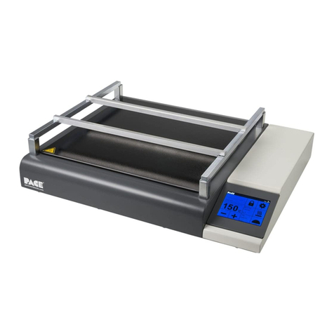
Pace PH 100 User manual

Pace

Pace PH 100 User manual

Pace HS 300 User manual

Pace

Pace HS 300 User manual

Popular Heater manuals by other brands

Sector ERAD500/7DT Installation and operating instructions

Sector

Sector ERAD500/7DT Installation and operating instructions

Jaga eCAB instructions

Jaga

Jaga eCAB instructions

COZY VC201A and Installation and operating instructions

COZY

COZY VC201A and Installation and operating instructions

Dimplex Winslow SWM3520-EU owner's manual

Dimplex

Dimplex Winslow SWM3520-EU owner's manual

Far Group Farelek YQ-12 manual

Far Group

Far Group Farelek YQ-12 manual

SAMITECH Heat Wrap user manual

SAMITECH

SAMITECH Heat Wrap user manual

ecofort ecoheat Hybrid-T instruction manual

ecofort

ecofort ecoheat Hybrid-T instruction manual

Stroco 15.00 M Service instructions

Stroco

Stroco 15.00 M Service instructions

Coleman 513A708 manual

Coleman

Coleman 513A708 manual

Suntec Wellness KLIMATRONIC Heat Supreme 2000 manual

Suntec Wellness

Suntec Wellness KLIMATRONIC Heat Supreme 2000 manual

Helios AIR1-EVH RH Installation and operating instructions

Helios

Helios AIR1-EVH RH Installation and operating instructions

Olimpia splendid CALDO CRYSTAL Instructions for installation, use and maintenance

Olimpia splendid

Olimpia splendid CALDO CRYSTAL Instructions for installation, use and maintenance

ThermoUp FLOOR manual

ThermoUp

ThermoUp FLOOR manual

Reznor UBX Installation operation & maintenance

Reznor

Reznor UBX Installation operation & maintenance

ARDES AR4W08P Instructions for use

ARDES

ARDES AR4W08P Instructions for use

Avenger BLUE FLAME FDT1IR BLUE FLAME FDT2IR OWNER'S OPERATION AND INSTALLATION MANUAL

Avenger

Avenger BLUE FLAME FDT1IR BLUE FLAME FDT2IR OWNER'S OPERATION AND INSTALLATION MANUAL

STEGO HGL 046 quick start guide

STEGO

STEGO HGL 046 quick start guide

Micasa MA0136PH instruction manual

Micasa

Micasa MA0136PH instruction manual

manuals.online logo
manuals.online logoBrands
  • About & Mission
  • Contact us
  • Privacy Policy
  • Terms and Conditions

Copyright 2025 Manuals.Online. All Rights Reserved.