1
12V AUTOMATIC LITHIUM BATTERY CHARGER
This is a fully automatic lithium battery charger with 8 charge stages.
Automatic charging protects your battery from being overcharged. So you can
leave the charger connected to the battery indefinitely.
8-stage charging is a very comprehensive and accurate charging process that
gives your battery longer life and better performance compared to using
traditional chargers.
The 8-stage chargers is designed for Lithium-ion batteries using LiFePO4
technology only.
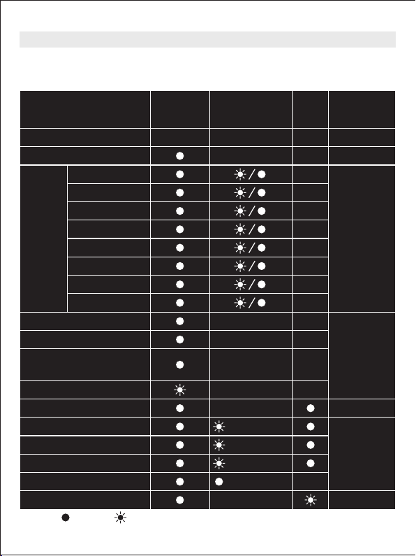
The 8 stages are:
Soft Start, Bulk, Absorption, Analyse, Completion, Maximization, Float And
Maintain.
◆ Explosive gases may escape from the battery during charging. Prevent
flames and sparks. Provide adequate ventilation.
◆ Before charging, read the instructions.
◆ For indoor use. Do not expose to rain.
◆ For charging 12 Volt lithium-ion with LiFePO4 batteries ONLY.
◆ Disconnect the 110V/220-240V AC mains supply before making or breaking
the connections to the battery.
◆ The battery charger must be plugged into an earthed socket-outlet.
◆ Connection to supply mains is to be in accordance with National wiring rules.
◆ Do not attempt to charge non-rechargeable batteries.
◆ Never charge a frozen battery.
◆ If the AC cord is damaged do not attempt to use. It must be replaced or
repaired by a qualified person.
◆ Corrosive substances may escape from the battery during charging and
damage delicate surfaces. Store and charge in a suitable area.
◆ Ensure all vehicle accessories including lights, heaters, appliances etc are
turned off prior to charging.
◆ This appliance is not intended for use by young children or infirm persons
unless they have been adequately supervised by a responsible person to
ensure that they can use the appliance safely.
◆ Young children should be supervised to ensure that they do not play with the
appliance.
1. WARNING
2. FEATURES