1258
, .
•
T-65
FEATURES
AND
SPECIFICATIONS
TESTS: Low
power,
medium
power,
and
power
type
transistors,
NPN
and
PNP
types.
TESTS:
Crystal
diodes
for
forward
(Di) and
reverse
(Dr)
current
in
comparison
with
manufacturer'S
specifications.
ALL TRANSISTOR TESTS READ ON ONE
0-100
METER
SCALE:
Direct
test
limits
for
each
transistor
listed
on
the
accompanying
data
sheets.
TWO PANEL-MOUNTED TRANSISTOR SOCKETS:
Supplemented
by a
universal
alligator-terminated
cable
to
provide
connection
facilities
for
all
transistors.
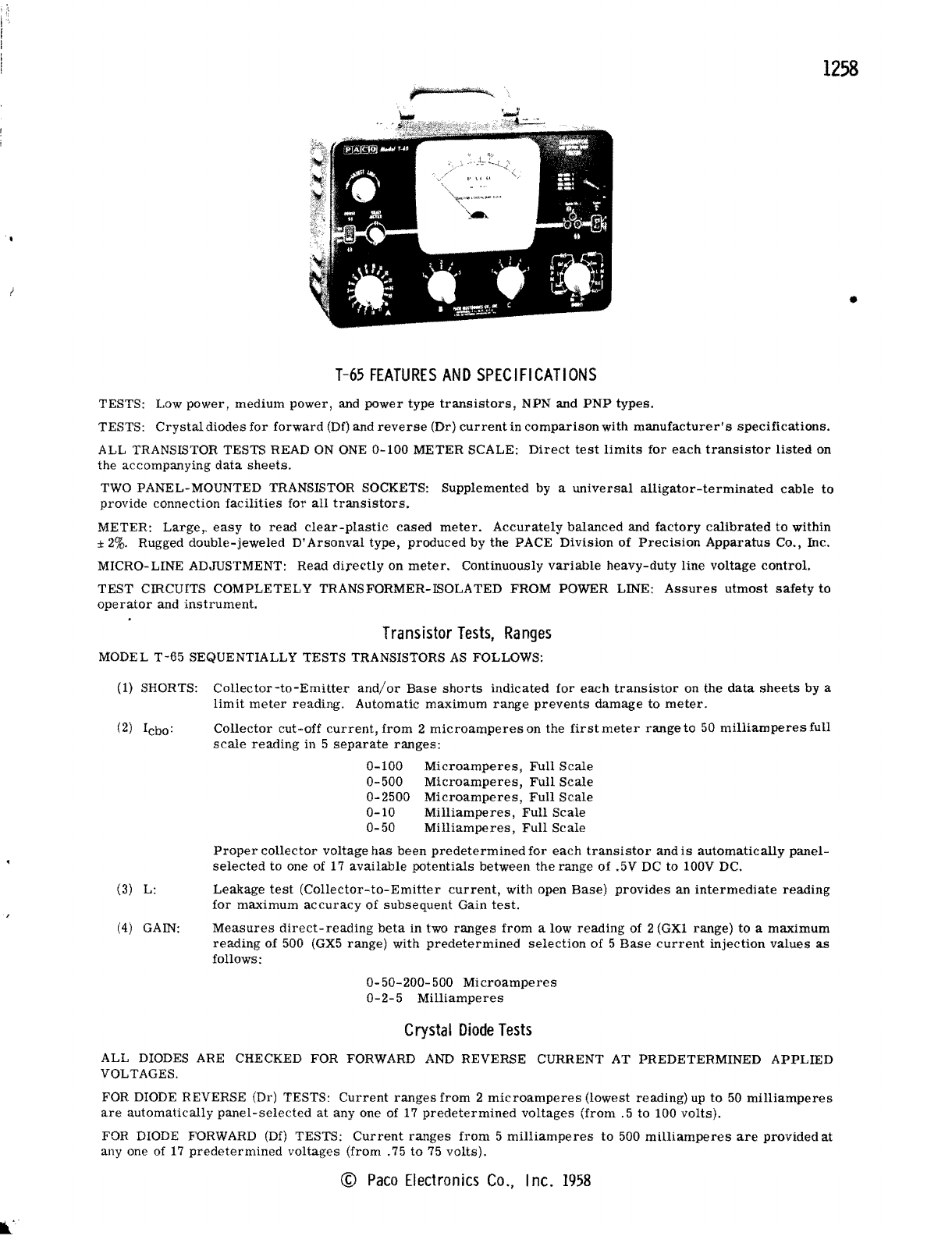
METER:
Large,.
easy
to
read
clear-plastic
cased
meter.
Accurately
balanced
and
factory
calibrated
to
within
±
2%.
Rugged
double-jeweled
D'
Arsonval
type,
produced
by
the
PACE
Division
of
Precision
Apparatus
Co., Inc.
MICRO-LINE ADJUSTMENT:
Read
directly
on
meter.
Continuously
variable
heavy-duty
line
voltage
control.
TEST
CIRCUITS
COMPLETELY
TRANSFORMER-ISOLATED FROM POWER LINE:
Assures
utmost
safety
to
operator
and
instrument.
Transistor
Tests,
Ranges
MODEL
T-65
SEQUENTIALLY TESTS TRANSISTORS
AS
FOLLOWS:
(1)
SHORTS:
Collector-to-Emitter
and/or
Base
shorts
indicated
for
each
transistor
on the
data
sheets
by a
limit
meter
reading.
Automatic
maximum
range
prevents
damage
to
meter.
(2)
lebo:
Collector
cut-off
current,
from
2
microamperes
on
the
first
meter
range
to 50
milliamperes
full
scale
reading
in 5
separate
ranges:
0-100
Microamperes,
Full
Scale
0-500
Microamperes,
Full
Scale
0-2500
Microamperes,
Full
Scale
0-10
Milliamperes,
Full
Scale
0-50
Milliamperes,
Full
Scale
Proper
collector
voltage
has
been
predetermined
for
each
transistor
and
is
automatically
panel-
selected
to one of 17
available
potentials
between
the
range
of
.5V DC to 100V DC.
(3)
L·
Leakage
test
(Collector-to-Emitter
current,
with open
Base)
provides
an
intermediate
reading
for
maximum
accuracy
of
subsequent
Gain
test.
(4) GAIN:
Measures
direct-reading
beta
in
two
ranges
from
a low
reading
of 2 (GXI
range)
to a
maximum
reading
of
500
(GX5
range)
with
predetermined
selection
of 5
Base
current
injection
values
as
follows:
0-50-200-500
Microamperes
0-2-5
Milliamperes
Crystal
Diode
Tests
ALL DIODES ARE CHECKED FOR FORWARD
AND
REVERSE CURRENT AT PREDETERMINED
APPLIED
VOLTAGES.
FOR DIODE REVERSE (Dr) TESTS:
Current
ranges
from
2
microamperes
(lowest
reading)
up
to
50
milliamperes
are
automatically
panel-selected
at
anyone
of 17
predetermined
voltages
(from.
5 to 100
volts).
FOR DIODE FORWARD
(Df)
TESTS:
Current
ranges
from
5
milliamperes
to 500
milliamperes
are
provided
at
anyone
of
17
predetermined
voltages
(from.
75
to
75
volts).
©
Paco
Electronics
Co.,
Inc.
1958
t.: