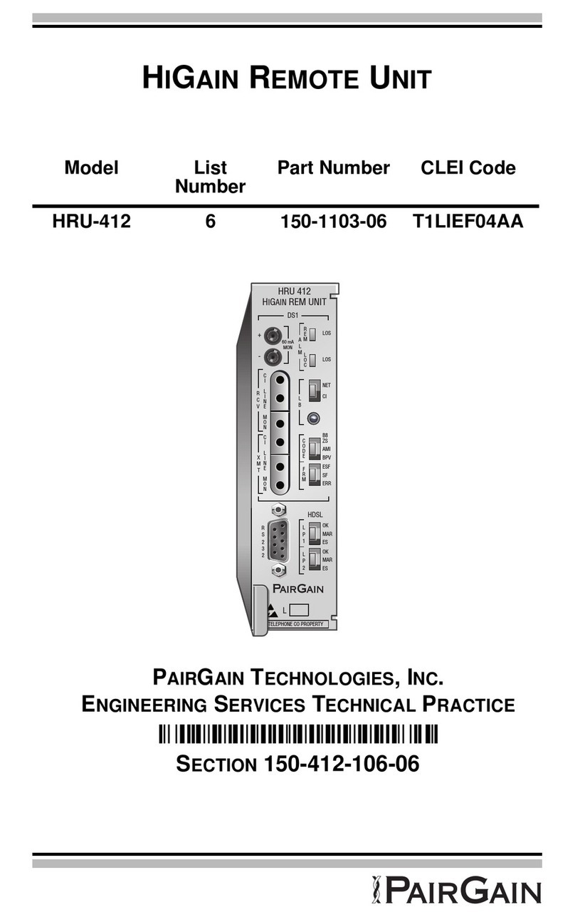
PairGain HIGAIN HRU-412 User manual

HIGAIN REMOTE UNIT
PAIRGAIN TECHNOLOGIES, INC.
ENGINEERING SERVICES TECHNICAL PRACTICE
™150-412-108-02B¨
SECTION 150-412-108-02
Model List Number Part Number CLEI Code
HRU-412 8 150-1103-08 T1L2CC0AAA

150-412-108-02, Revision 02
ii July 13, 1998 HRU-412 List 8
Revision History of This Practice
©Copyright 1998 PairGain Technologies, Inc.
PairGain, and HiGain are registered trademarks of PairGain Technologies, Inc.
Information containedin thisdocumentis company private to PairGain Technologies,Inc.,
and shall not be modified, used, copied, reproduced or disclosed in whole or in part without
the written consent of PairGain.
Other product names mentioned in this practice are used for identification purposes only
and may be trademarks or registered trademarks of their respective companies.
Revision Release Date Revisions Made
02 July 13, 1998 Modified and Updated
01 March 22, 1996 Initial Release

150-412-108-02, Revision 02 Using This Technical Practice
HRU-412 List 8 July 13, 1998 iii
USING THIS TECHNICAL PRACTICE
Two types of messages, identified by icons, may appear in the text.
ABBREVIATIONS
Notes contain information about special circumstances.
Cautions indicate the possibility of equipment damage or the
possibility of personal injury.
AMI Alternate Mark Inversion
BER Bit Error Rate
BPV Bipolar Violations
B8ZS Binary Eight Zero Substitution
CO Central Office
CRC Cyclic Redundancy Check
CSA Carrier Service Area
ES Errored Seconds
ESF Extended Superframe
HDSL High-bit-rate Digital Subscriber Line
HLU HiGain Line Unit
HRU HiGain Remote Unit

Abbreviations 150-412-108-02, Revision 02
iv July 13, 1998 HRU-412 List 8
SF Super Frame
SNR Signal-to-Noise Ratio
SPLB Special Loopback
ZBTSI Zero Byte Time Slot Interface

150-412-108-02, Revision 02 Table of Contents
HRU-412 List 8 July 13, 1998 v
TABLE OF CONTENTS
Overview _______________________________________________ 1
Applications ____________________________________________ 2
Specifications ___________________________________________ 3
Functional Description____________________________________ 5
Operational Capabilities........................................................... 5
Front Panel Features ................................................................ 7
Rear Panel Features................................................................ 10
Local and Line Powering....................................................... 12
Installation ____________________________________________ 14
Unpack and Inspect the Shipment.......................................... 14
Install the HRU-412 List 8..................................................... 14
Installation Test...................................................................... 16
Provision and Monitor Performance _______________________ 18
Connect an ASCII Terminal .................................................. 18
Log On and Use the Menus ................................................... 19
View Span Status..................................................... 22
Set Clock ................................................................. 24
System Settings ....................................................... 25
View Performance Data .......................................... 26
View 7 Day History................................................. 27
View Alarm History................................................28
Loopbacks _____________________________________________ 30

Table of Contents 150-412-108-02, Revision 02
vi July 13, 1998 HRU-412 List 8
Product Support_________________________________________33
Technical Support...................................................................33
Warranty.................................................................................34
FCC Compliance....................................................................35
Modifications..........................................................................35
UL Listing ..............................................................................35
CSA Certification...................................................................36

150-412-108-02, Revision 02 List of Figures
HRU-412 List 8 July 13, 1998 vii
LIST OF FIGURES
1. HRU-412 List 8 Block Diagram ........................................................6
2. HRU-412 List 8 Front Panel ..............................................................7
3. HRU-412 List 8 Rear Panel.............................................................. 10
4. HRU-412 List 8 Pinouts................................................................... 15
5. HRU-412 List 8 Craft Port Wiring...................................................18
6. Remote Logon Screen...................................................................... 20
7. Main Menu, Local Log On............................................................... 21
8. Span Status Screen, No Doublers in Use ......................................... 22
9. Span 1 Status Screen, Doublers in Use ............................................ 23
10. Set Clock Screen ............................................................................ 24
11. System Settings Menu.................................................................... 25
12. Performance Data Screen............................................................... 26
13. 7 Day History Screen ..................................................................... 27
14. Alarm History Screen..................................................................... 28
15. HRU-412 List 8 Loopbacks ........................................................... 30

List of Tables 150-412-108-02, Revision 02
viii July 13, 1998 HRU-412 List 8
LIST OF TABLES
1. HDSL Loss Over Cables.....................................................................3
2. HRU-412 List 8 Front Panel Components..........................................8
3. Rear Panel Components....................................................................11
4. HRU-412 List 8 Alarm History Screen Definitions .........................29

150-412-108-02, Revision 02 Overview
HRU-412 List 8 July 13, 1998 1
OVERVIEW
The PairGain®HiGain®Remote Unit Model HRU-412 List 8 is the remote
end of a repeaterless T1 transmission system. An HRU-412 List 8 connects
to a HiGain Line Unit (HLU), creating a HiGain system which provides 1.544
Mbps transmission on two unconditioned copper pairs over the full Carrier
Service Area (CSA) range. The CSAencompasses approximately 12,000 feet
of AWG 24 wire or 9,000 feet of AWG 26 wire, including bridge taps and
gauge changes. A HiGain system utilizes 2B1Q High-bit-rate Digital
Subscriber Line (HDSL) transmission technology. The HRU-412 List 8
complies with ANSI T1E1.4, T1.403-1989, and T1E1.4/92-002R2 technical
standards and recommendations. The HRU-412 List 8 mounts in a single slot
of an industry standard 400 Mechanics type shelf. The system also complies
with GR-63 Core of Network Equipment Building System (NEBS) Generic
Equipment requirements, and Transport System Generic Requirements
(TSGR) common requirements TR-TSY-000499.
The HRU-412 List 8 features:
•Customer Interface (CI)
•Front panel DS1 and HDSL LEDs
•Front panel loopback button
•Signature resistance on DS1 and HDSL ports
•Generic and addressable repeater loopback activation codes
•Metallic SmartJack loopback (conforms to TR-TSY-000312)
•Provisioning switches for customer premise equipment (CPE) current,
receive (RCV) level, and transmit loss of signal (TLOS) initiated
loopback or alarm
•Line or local power options
•Sealing current
•Front panel jacks for test access
•Craft port
•CPE current monitor test points
•Front panel HDSL margin threshold indicator for each loop
•Lightning and power cross protection on HDSL and DS1 interfaces
Applications 150-412-108-02, Revision 02
2 July 13, 1998 HRU-412 List 8
•784kbps full-duplex 2B1Q HDSL transmission on two pairs
•DS0 blocking support
The HRU-412 List 8 supports PairGain’s 1 x 1 Protection Switching System.
The HRU-412 List 8 can be line powered or locally powered and has a
simplexed sealing current option. The HDSL line input resistive signature is
14 Ω.
APPLICATIONS
A HiGain system, consisting of a HiGain line unit and a HiGain remote unit,
provides a quick and cost-effective way of delivering T1 High Capacity
Digital Service (HCDS) to customers over copper pairs. The HiGain system
can be deployed on two unconditioned, non-loaded copper pairs without
repeaters, and without the need for bridged tap removal or binder group
separation.
The generalguidelines for HiGain system usage isthat each loop has less than
35 dB of loss at 196 kHz, with 135 Ωdriving and terminating impedances.
Table 1 provides a guide for the loss over various cable gauges at 196 kHz
and135Ω.The tableappliestothe HDSL cable pairs between theHiGain line
unitand theHiGainremoteunit.Without specific loop insertion lossdata, add
3 dB for each bridged tap and 1 dB for each cable gauge change.
The dc cable resistance determines the simplex powering resistance path of
the loops. The maximum allowable resistance for a HiGain system is 800 Ω
over two HDSL simplex loops. This means, for example, where 12 kft AWG
24 equals 34.08 dB (insertion loss) resistance is at 622 Ω, which is well below
the limit of 800 Ω.
The HRU-412 List 8 supports PairGain’s 1 x 1 Protection
Switching System.

150-412-108-02, Revision 02 Specifications
HRU-412 List 8 July 13, 1998 3
A HiGain system operates with a variety of other T1, POTS, Digital Data
Service (DDS) equipment or other HiGain systems sharing the same cable
binder group. HiGain systems provide temporary or permanent DS1 service
and can provide a means of deploying service in advance of fiber-optic
transmission systems.
SPECIFICATIONS
HDSL
Line Code 884 kbps 2B1Q full duplex
Output +13 dBm + 0.5 dB at 135 Ω
Line Impedance 135 Ω
Startup Time 15 seconds (typical), 60 seconds (maximum)
Maximum Provisioning Loss
35 dB at 196 kHz, 135 Ω
Line Clock Rate
Internal Stratum 4 clock
Power Consumption
6 Watts (typical), 8 Watts (maximum)
Table 1. HDSL Loss Over Cables
Cable Gauge Loss at 196 kHz
(db/kft) Ohms per kft
26/0.4mm 3.88 83
24/0.51mm 2.84 52
22/0.61mm 2.18 32
19/0.91mm 1.54 16

Specifications 150-412-108-02, Revision 02
4 July 13, 1998 HRU-412 List 8
Electrical Protection
Secondary surge and power cross protection on all DS1 and HDSL ports
Environmental
Operating Temperature - 40° C to + 65° C
Humidity 5 to 95% (non-condensing)
Mounting
Single wide 400 Mechanics type shelf
DS1
Dimensions
Height: 5.6 in. (14.22 cm)
Width: 1.4 in. (3.55 cm)
Depth: 5.6 in. (14.22 cm)
Weight: 1 lb. 2 oz. (510.85 g)
One-way Delay < 220 microseconds per span
Line Impedance 100 Ω
Pulse Output 0 dB (RLEV = 0), -15 dB (RLEV = 15)
Input Level > -22.5 dB
Line Rate 1.544 Mbps + 200 bps
Output Wander
(MTIE and TVAR) Compliant with Section 8.2.1 of the
T1X1.3/90-026R8 SONET committee
report
Line Format AMI, B8ZS, or ZBTSI
Frame Format ESF, SF, or unframed

150-412-108-02, Revision 02 Functional Description
HRU-412 List 8 July 13, 1998 5
FUNCTIONAL DESCRIPTION
This section describes the functions of the HRU-412 List 8.
OPERATIONAL CAPABILITIES
HiGain utilizes PairGain’s 2B1Q HDSL transceiver system to establish two
full-duplex784kbpsdatachannelsbetween the HLU anda remotelymounted
HRU-412 List 8. This provides a total capacity of 1.568 Mbps between the
two units. PairGain’s HDSL technology provides full-duplex services at
standard T1 rates over copper wires between an HLU and an HRU, which
comprise one HiGain system.
The HRU-412 List 8 power supply converts the power feed voltage received
on the simplex pairs (or the -48 Vdc input when locally powered) to voltages
and currents required by the HRU-412 circuitry. The power supply generates
+5, -5 and 30 Vdc outputs. The 30 Vdc output is converted to a 60 mA current
feed topower a Network Interface Device (NID) ifrequired. Exercise caution
when powering a unit that requires more than 30 Vdc. The HRU-412 List 8
cannot power a NID and another product simultaneously.
The HRU-412 List 8 dissipates 6 Watts of power and may consume up to 8
Watts when feeding 60 mA of simplex current to the CI.
The HRU-412 List 8 can be used with the HLU-232 line unit to form an
automatic 1 x 1 protection switch system. For this application, the HRU-412
List 8 must be installed in the two slot HRE-422 remote enclosure. This
enclosure provides access to the HRU-412 List 8 protection switch output, on
pins 12 and 40, which control the protection switching function.

Functional Description 150-412-108-02, Revision 02
6 July 13, 1998 HRU-412 List 8
Figure 1 shows a block diagram of the HRU-412 List 8.
Figure 1. HRU-412 List 8 Block Diagram

150-412-108-02, Revision 02 Functional Description
HRU-412 List 8 July 13, 1998 7
FRONT PANEL FEATURES
Figure 2 shows the front view of the HRU-412 List 8. Table 2 describes the
HRU-412 List 8 front panel components.
Figure 2. HRU-412 List 8 Front Panel
HRU 412
HiGain REM UNIT
DS1
LOS
LOS
A
L
M
60mA
MON
R
E
M
L
O
C
R
C
V
C
I
L
I
N
E
M
O
N
L
B
NET
CI
C
I
L
I
N
E
M
O
N
X
M
T
C
O
D
E
F
R
M
B8
ZS
AMI
BPV
ESF
SF
ERR
HDSL
L
P
1
OK
MAR
ES
OK
MAR
ES
L
P
2
R
S
2
3
2
PairGain
L
TELEPHONE CO PROPERTY
Loopback (LB) LEDs
Code LEDs
Framing (FRM) LEDs
Alarm (ALM) LEDs
Loopback (LB) button
Test points
Receive (RCV)
and Transmit (XMT)
Access Jacks
Craft port
Card handle Configuration number
(inside handle)
HDSL LEDs

Functional Description 150-412-108-02, Revision 02
8 July 13, 1998 HRU-412 List 8
Table 2. HRU-412 List 8 Front Panel Components
Name Function
Test points Allow the 60 mA CPE current option to be measured. The current flowing
is related to the voltage measured across the + and - test points by the
following relationship: CPE CURRENT = 1 MA/1 MV. Typical readings
range from 55 to 65 mV, which equate to a 55 to 65 mA current range.
Receive
(RCV) and
transmit
(XMT) jacks
Provide splitting and monitor access to the CPE DS1 interface. The jacks
are transformer isolated from the CPE DS1 metallic interface.
Alarm LEDs REM LOS LED lights red to indicate a loss of signal (LOS) at the T1 input
to the HLU. This LOS condition causes the HRU-412 List 8 to transmit the
alarm indicating signal (AIS) pattern toward the CPE.
LOC LOS LED lights red to indicate a loss of signal (LOS) at the T1 input
to the HRU-412 List 8. This LOS condition transmits the AIS pattern
toward the DSX-1 (TLOS Disabled) or to execute a logic loopback in the
HRU-412 List 8 (TLOS Enabled).
Loopback
(LB) LEDs
NET LED lights green to indicate the HRU-412 List 8 is in a loopback state
where the signal from the network is looping back to the network.
CIS LED lights yellow to indicate the HRU-412 List 8 is in a loopback state
in which the signal from the customer interface (CI) is looping back to the
CI.
Code LEDs B8ZS LED lights green to indicate that the user DS1 code option is set to
B8ZS.
AMI LED lights yellow to indicate that the user DS1 code option is set to
AMI.
BPV LED lights red to indicate that the user DS1 code option is set to BPV.
If the user DS1 code option is set to AUTO, the lit LED indicates what DS1
signal is being received. Note that these settings are made on the HLU.
Framing
LEDs
ESF LED lights green to indicate that the framing pattern of the received
signal is Extended Super Frame (ESF).
SF LED lights yellow to indicate that the framing pattern of the received
signal is Super Frame (SF).
ERR LED lights red to indicate that a DS1 frame error has occurred.
No frame LED lights when the HRU-412 List 8 input pattern is unframed
or when the framing option is set to UNFR (unframed). Note that this
settings is made on the HLU.

150-412-108-02, Revision 02 Functional Description
HRU-412 List 8 July 13, 1998 9
HDSL LEDs LP1 OK LED flashes green while HDSL Loop 1 is synchronizing with the
HLU. The LED lights green to indicate that loop 1 is properly synchronized
with the HLU.
LP1 MAR LED lights yellow when the HRU-412 List 8 margin on HDSL
loop 1 has dropped below the user-defined margin threshold value. This
indicator flashes yellow at a slow rate to indicate that a loss of sync word
(LOSW) exists in span 1, loop 1 of the HDSL pair between the HLU and the
doubler. This indicator flashes yellow at a rapid rate to indicate that a
LOSW problem exists in span 2, loop 1 of the HDSL pairs between the first
and second doublers.
LP1 ES LED flashes red every second that a CRC error is detected on loop
1 from the upstream module.
LP2 OK LED flashes green while HDSL Loop 1 is synchronizing with the
HLU. The LED lights green to indicate that loop 2 is properly synchronized
with the HLU.
LP2 MAR LED lights yellow when the HRU-412 List 8 margin on HDSL
loop 2 has dropped below the user-defined margin threshold value. This
indicator flashes yellow at a slow rate to indicate that a loss of sync word
(LOSW) exists in span 1, loop 2 of the HDSL pair between the HLU and the
doubler. This indicator flashes yellow at a rapid rate to indicate that a
LOSW problem exists in span 2, loop 2 of the HDSL pairs between the first
and second doublers.
LP2 ES LED flashes red every second that a CRC error is detected on
loop 2 from the upstream module.
RS-232
(Craft) port
Provides a connection port for an ASCII terminal. The ASCII terminal
allows access to the maintenance, provisioning, and performance
monitoring menus and screens.
Card handle Pull on the card handle to remove the HRU-412 List 8 from the shelf slot.
Configuration
Number
Contains either a five or six-digit warranty configuration number or a
stand-alone two or three-digit configuration number as follows:
Digit 1 - Last digit of shipment year
Digit 2 and 3 - Shipment month
Digit 4, 5, and 6 - Configuration number
Table 2. HRU-412 List 8 Front Panel Components (Cont.)
Name Function

Functional Description 150-412-108-02, Revision 02
10 July 13, 1998 HRU-412 List 8
REAR PANEL FEATURES
The HRU-412 List 8 back panel features are shown in Figure 3. Table 3
describes the features.
Figure 3. HRU-412 List 8 Rear Panel

150-412-108-02, Revision 02 Functional Description
HRU-412 List 8 July 13, 1998 11
Table 3. Rear Panel Components
Switch Setting Function
I-CPE 0Sets the CPE current to 0 mA.
60 Sets the CPE current to 60 mA to power an external NID.
The CPE current control signals terminate on pins 32 and 34 of the card-edge
converter. These access pins are for factory test only and are not used. Single
slot remote enclosures and seven slot enclosures use the pins to control the
CPE options in older HRU units. These enclosures must be optimized for 0
mA current to prevent a conflict between external connections to pins 32 and
34 and the settings of the I-CPE switch.
TLOS-LB DIS Does not allow the HRU-412 List 8 to enter its logic loopback state
when a loss of the T1 XMT signal from the CPE causes the HLU to
transmit the AIS signal toward the DSX-1.
EN Allows the HRU-412 List 8 to enter its logic loopback state when a
loss of the T1 XMT signal from the CPE causes the HLU to transmit
the AIS signal toward the DSX-1. While in this loopback state, the
HRU-412 List 8 transmits the AIS signal toward the CPE and
returns the network signal back to the network. The HLU displays
TLOS in its front panel display. This condition remains until a valid
T1 signal is received from the CPE or until the 3-in-5 in-band
loopdown command is issued. Once the TLOS initiated loopback
occurs, it will not reoccur until the CPE T1 signal has been
reapplied and then removed. This feature prevents the HRU-412
List 8 from oscillating into and out of TLOS loopback when a
loopdown command is issued in the absence of a T1 signal from
the CPE. This TLOS option must never be enabled when the
HRU-412 List 8 is used with old line units that do not support this
feature. These older line units (List 6 and under) cannot loopdown
an HRU-412 List 8 that is in a TLOS loop-up state when they
receive the 3-in-5 in-band loopdown command.

Functional Description 150-412-108-02, Revision 02
12 July 13, 1998 HRU-412 List 8
LOCAL AND LINE POWERING
The HRU-412 List 8 unit can be line powered or local powered. It always
chooses the local -48 Vdc power source, if present. It defaults to line power
only in the absence of local power. Some older HLUs automatically turn off
their line powering when connected to the HRU-412 List 8. The older
versions of the HLU-231(Lists 1, 2, 3, 3A, and4) must have their PWRF user
option disabled for them to work properly with a locally powered HRU-412
List 8. Refer to the appropriate HLU technical practice if you need more
information about its local and line powering capabilities.
When locally powered, the HRU-412 List 8 provides 15 mA (short loop) to
10 mA (long loop) simplex sealing current toward all versions of the HLU
over the two HDSL pairs. JP2, shown in Figure 3, allows the sealing current
to be enabled or disabled. To enable the sealing current, connect JP2 across
both terminals. To disable the sealing current, remove the jumper from the
inner terminal and attach it to the outer terminal. The factory default setting
is disabled. This simplexed sealing current is polarity sensitive and will not
flow if the HDSL loops at the HRU-412 List 8 are reversed. Reversed loops
are indicated by a CHREV message in the ALARMS line of the Span Status
screen.
RLEV 0Configures the T1 RCV level to 0 dB. This sets the T1 output signal
level from the HRU-412 List 8 toward the NI to 0 dB. Use this
setting when the HRU-412 List 8 is not functioning as a NID but is
connected to an external NID. It allows the external NID to set the
appropriate NI level.
15 Configures the T1 RCV level to -15 dB. This sets the T1 output
signal level from the HRU-412 List 8 toward the NI level to -15 dB.
This setting is recommended when the HRU-412 List 8 functions
as a NID.
JP2 Allows the enabling or disabling of the sealing current. To enable,
connect JP2 across both terminals. To disable (default), remove
the jumper from the inner terminal and leave it attached to the
outer terminal only.
Table 3. Rear Panel Components (Cont.)
Switch Setting Function
Other manuals for HIGAIN HRU-412
6
This manual suits for next models
1
Table of contents
Other PairGain Remote Control manuals

PairGain
PairGain HLU-319 User manual

PairGain
PairGain HIGAIN HRU-412 User manual

PairGain
PairGain HIGAIN HRU-412 User manual

PairGain
PairGain HiGain HRU-402 User manual

PairGain
PairGain PRL-770 User manual

PairGain
PairGain HiGain-2 HRU-612 User manual

PairGain
PairGain HIGAIN HRU-412 User manual

PairGain
PairGain HIGAIN HRU-412 User manual

PairGain
PairGain HIGAIN HRU-412 User manual

PairGain
PairGain HiGain Solitaire H2TU-R-402 User manual