Revision 01 July 9, 1997 Section 150-412-109
HiGain HRU-412 PairGain Engineering - Plant Series Page 5
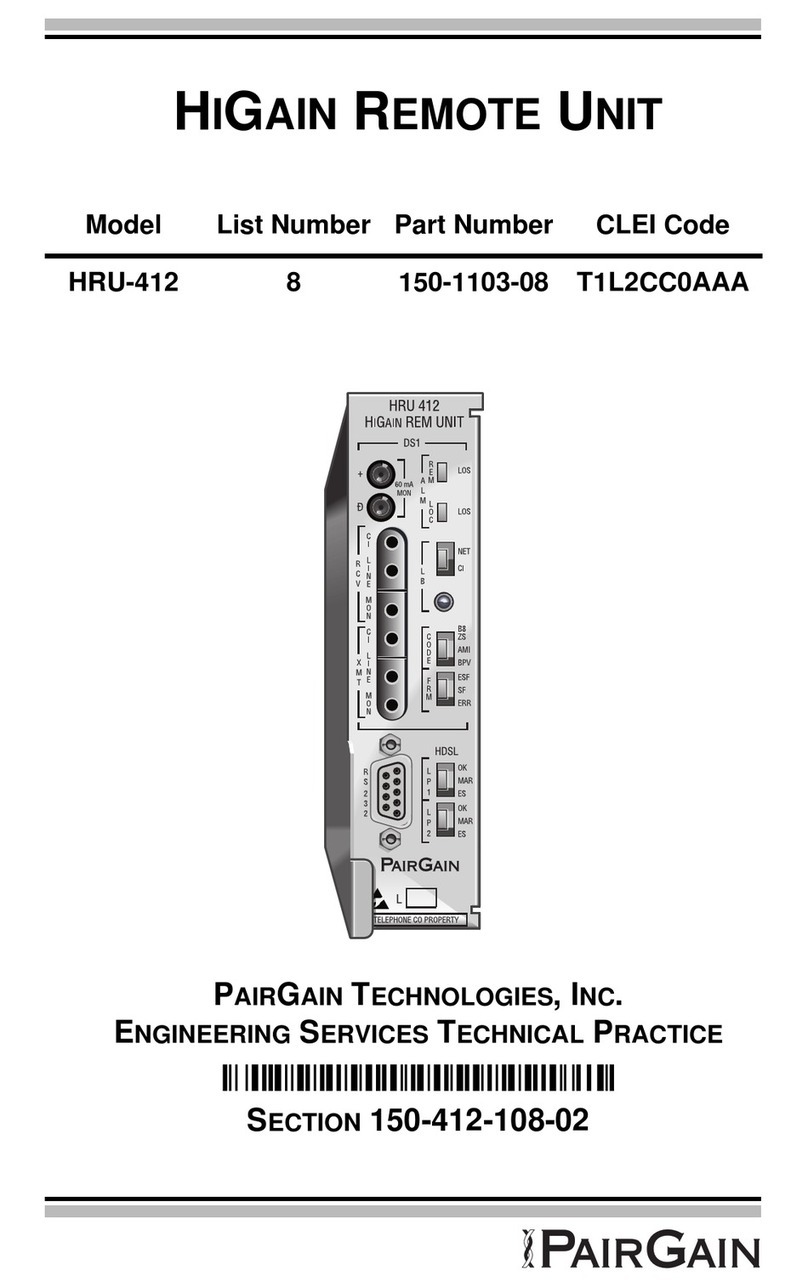
Table 3. Reading the HRU-412 Front Panel LEDs
Name Mode Description
REM LOS Steady red LOS detected at the T1 input to the remote HLU unit. This condition causes the
HRU to transmit the AIS pattern towards the CPE.
Off Normal transmission of data.
LOC LOS Steady red LOS detected at the T1 input to the local HRU unit. This condition causes an
AIS-CI signal to be transmitted towards the customer and an AIS-CI signal to
be sent to the DSX-1 from the HLU. This state is not sent to the HLU and does
not register an LOS ALRM condition.
Off Normal transmission of data.
NET Steady green The HRU is in a loopback state in which the signal from the NET is being
looped back to the NET.
Off No NET loopbacks are active.
CI Steady yellow The HRU is in a loopback state in which the signal from the CI is being looped
back to the CI.
Off No CI loopbacks are active.
B8ZS Steady green DS1 line code option set to B8ZS. If however the user DS1 line code option is
set to Auto, LED indicates that the code of the DS1 signal being received at the
HRUs DS1 input is B8ZS.
AMI Steady yellow DS1 line code option set to AMI. If the user DS1 line code option is set to
Auto, LED indicates that the code of the DS1 signal being received at the HRUs
DS1 input is AMI.
BPV Blinking red Blinks every time a BPV, other than those associated with a B8ZS code, is
received at the HRUs DS1 input.
ESF Steady green Indicates that framing pattern of the signal being received at the HRUs DS1
input is ESF.
SF Steady yellow Indicates that framing pattern of the signal being received at the HRUs DS1
input is SF.
ERR Steady red Indicates a DS1 frame error has occurred.
LP1
OK Blinking green HDSL Loop 1 is synchronizing with the HLU.
Steady green HDSL Loop 1 is synchronized and ready to receive and transmit data.
MAR Blinking yellow Indicates a problem in Loop 1 (doubler applications only) of the HDSL cable
pairs that are non-adjacent to the HRU. Blinking once per second indicates a
Loss of Sync Word (LOSW) problem in Span 1’s Loop 1 HDSL pair between
the HLU and doubler. Blinking twice per second indicates a LOSW problem in
Span 2’s Loop 1 HDSL pair between the first and second doublers.
ES Blinking red Blinks every second in which at least one HDSL CRC error is detected on Loop
1 from the upstream module.
LP2
OK Blinking green HDSL Loop 2 is synchronizing with the HLU.
Steady green HDSL Loop 2 is synchronized and ready to receive and transmit data.
MAR Blinking yellow Indicates a problem in Loop 2 (doubler applications only) of the HDSL cable
pairs that are non-adjacent to the HRU. Blinking once per second indicates a
LOSW problem in Span 2’s Loop 2 HDSL pair between the HLU and doubler.
Blinking twice per second indicates a LOSW problem in Span 2’s Loop 2
HDSL pair between the first and second doublers.
ES Blinking red Blinks every second in which at least one HDSL CRC error is detected on Loop
2 from the upstream module.
