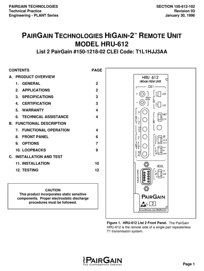
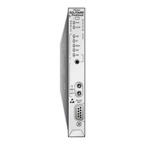
PairGain HiGain HRU-402 User manual

HIGAIN REMOTE UNIT
PAIRGAIN TECHNOLOGIES, INC.
ENGINEERING SERVICES TECHNICAL PRACTICE
™150-402-102-01S¨
SECTION 150-402-102-01
Model List Number Part Number
HRU-402 2 150-1592-02

150-402-102-01, Revision 01
ii July 27, 1998 HRU-402 List 2
Revision History of This Practice
©Copyright 1998 PairGain Technologies, Inc.
PairGain and HiGain are registered trademarks of PairGain Technologies, Inc.
Information containedin thisdocumentis company private to PairGain Technologies,Inc.,
and shall not be modified, used, copied, reproduced or disclosed in whole or in part without
the written consent of PairGain.
Other product names mentioned in this practice are used for identification purposes only
and may be trademarks or registered trademarks of their respective companies.
Revision Release Date Revisions Made
01 July 27, 1998 Initial release

150-402-102-01, Revision 01 Using This Manual
HRU-402 List 2 July 27, 1998 iii
USING THIS MANUAL
Two types of messages, identified by icons, appear in the text.
Notes contain information about special circumstances.
Cautions indicate the possibility of equipment damage or
the possibility of personal injury.

Using This Manual 150-402-102-01, Revision 01
iv July 27, 1998 HRU-402 List 2

150-402-102-01, Revision 01 Table of Contents
HRU-402 List 2 July 27, 1998 v
TABLE OF CONTENTS
Product Overview________________________________________ 1
Features.................................................................................... 2
Applications............................................................................. 3
Product Description ................................................................. 5
Front Panel................................................................. 5
Rear Panel.................................................................. 8
Installation ____________________________________________ 10
Inspecting Your Shipment ..................................................... 10
Installing the HRU-402 List 2................................................ 10
Installation Test...................................................................... 12
Front Panel Messages ............................................................13
Connecting to a Terminal Emulator....................................... 15
Using the Maintenance Terminal __________________________ 18
Login...................................................................................... 18
Navigating the HRU Maintenance Menus............................. 20
System Spans........................................................... 20
Navigation Keys ...................................................... 21
HRU Maintenance Terminal Main Menu.............................. 22
View Span Status..................................................... 23
Set Clock ................................................................. 27
System Settings ....................................................... 28
Loopback Menu....................................................... 30
View Performance Data .......................................... 33
View 7 Day History................................................. 36
View Alarm History................................................38
View System Inventory........................................... 40

Table of Contents 150-402-102-01, Revision 01
vi July 27, 1998 HRU-402 List 2
Appendix A: Additional Technical Information_______________42
Specifications .........................................................................42
Card-edge Pinout Diagram.....................................................44
Features ..................................................................................45
Bipolar Violation Transparency (BPVT) and Bit Error
Rate (BER) Options.................................................45
Remote DS1 Alarm (RDA) Option..........................46
Alarm Pattern Option (ALMP) Option....................47
DS1 Line Code Auto Option....................................47
Functional Description ...........................................................48
Operational Capabilities...........................................48
Local and Line Powering.........................................49
Simplex Sealing Current Information......................50
Loopback Design Description..................................51
SAIS Set to ENA .....................................................53
SAIS Set to DIS .......................................................53
Appendix B: Abbreviations _______________________________55
Appendix C: Product Support _____________________________58
Technical Support...................................................................58
Warranty.................................................................................59
FCC Compliance....................................................................60
Modifications..........................................................................60

150-402-102-01, Revision 01 List of Figures
HRU-402 List 2 July 27, 1998 vii
LIST OF FIGURES
Figure 1. Typical HiGain System........................................................... 1
Figure 2. Front Panel..............................................................................5
Figure 3. Backplane User Option Locations.......................................... 8
Figure 4. HRU-402 Installed in a Remote Enclosure........................... 11
Figure 5. DB-9 and DB-25 RS-232 I/O Interfaces............................... 16
Figure 6. Connecting the HRU-402 to a Maintenance Terminal......... 17
Figure 7. Local Login Main Menu Screen ........................................... 19
Figure 8. Remote Login Main Menu Screen........................................ 20
Figure 9. System Spans........................................................................ 20
Figure 10. Main Menu Remote Login Screen...................................... 23
Figure 11. View Span Status Screen for Non-doubler Applications.... 24
Figure 12. Span 5 Status Screen for Four Doubler Applications......... 25
Figure 13. Set Clock Screen................................................................. 27
Figure 14. System Settings Screen....................................................... 28
Figure 15. Loopback Screen Without Doublers................................... 31
Figure 16. Loopback Screen with Four Doublers ................................ 32
Figure 17. Performance Data Screen.................................................... 34
Figure 18. Span 5 Performance Data Screen........................................ 35
Figure 19. Performance History Screen for
Non-doubler Applications................................................... 36
Figure 20. Span 5 Performance Data Screen........................................ 37
Figure 21. Alarm History Screen for Non-doubler Applications......... 38
Figure 22. Four Doublers, Span 5 Alarm History Screen.................... 40
Figure 23. Inventory Screen................................................................. 41
Figure 24. Card-edge Pinouts............................................................... 44
Figure 25. HRU-402 List 2 Block Diagram......................................... 49
Figure 26. HiGain System Loopbacks .................................................52
List of Tables 150-402-102-01, Revision 01
viii July 27, 1998 HRU-402 List 2
LIST OF TABLES
Table 1. HDSL Loss Over Cables ..........................................................3
Table 2. Front Panel Components ..........................................................6
Table 3. Rear Panel Components............................................................9
Table 4. HLU-231 List 8 Four-Character Front Panel Messages ........13
Table 5. Maintenance Terminal Navigational Keys.............................21
Table 6. Maintenance and Remote Terminal Menus............................22
Table 7. Span Status Fields and Descriptions.......................................26
Table 8. System Settings Fields and Descriptions ...............................29
Table 9. Loopback Field Messages and Descriptions ..........................33
Table 10. Alarm History Fields and Descriptions ................................39

150-402-102-01, Revision 01 Product Overview
HRU-402 List 2 July 27, 1998 1
PRODUCT OVERVIEW
This technical practice describes the PairGain®HiGain®Remote Unit, Model
HRU-402 List 2, and its use with and without doubler and line units. This
remote unit functions as the remote end of a repeaterless T1 transmission
system. An HRU-402 List 2 connects to a HiGain Line Unit (HLU) and
HiGain Doubler Units (HDUs), creating a HiGain system which provides
1.544 Mbps transmission on two unconditioned copper pairs over the full
Carrier Service Area (CSA) range. See the section titled “Applications” on
page 3 for HiGain doubler and doubler compatible line units that can be used
with the HRU-402 List 2.
Figure 1 shows a basic HiGain configuration for a T1 High-bit-rate Digital
Subscriber Line (HDSL) circuit. The HLU is installed at the Central Office
(CO) shelf. The HRU-402 List 2 is housed in a remote enclosure at the
Customer PremisesEquipment(CPE)site.OptionalHDUs providetheability
toincreasethe range betweenthe HLUand HRU to five CSAspans.The CSA
encompasses approximately 60 kft of American Wire Gauge (AWG) wire.
Figure 1. Typical HiGain System

Product Overview 150-402-102-01, Revision 01
2 July 27, 1998 HRU-402 List 2
FEATURES
•Front panel with:
–Receive (RCV) and Transmit (XMT) Bridged (BDG) access jacks
for testing
–DS1 and HDSL status Light Emitting Diodes (LEDs)
–Craft port access (RS-232 DB-9 connector)
•American National Standards Institute (ANSI) T1.403 DS1 NI
•Generic and addressable repeater loopback activation codes
•Line power or local power options
•Optional sealing current
•Lightning and power cross protection on HDSL and DS1 interfaces
•784 kbps full-duplex 2B1Q HDSL Transmission on two pairs
•DS0 blocking
•Compatible with PairGain 1 x 1 Protection Switching System
•Narrow SLIM mechanics (half-width 400 mechanics)
•Lower Power Consumption
•Supports one to four span line powered and five span local powered
circuits
•Ultra Low Wander
•Improved DS1 Auto Mode
•Local/Line Power Switch
•BPVT and Bit Error Rate (BER) Options
•Remote DS1 Alarm (RDA) Option
•Alarm Pattern (ALMP) Option
•DS1 Line Code Auto Options
For additional information on features of the HRU-402 List 2, see “Features”
on page 45.

150-402-102-01, Revision 01 Product Overview
HRU-402 List 2 July 27, 1998 3
APPLICATIONS
The HiGain system provides a cost-effective and easy-to-deploy method for
delivering T1 service over a single metallic pair. Conventional in-line T1
repeaters, cable pair conditioning, pair separation, and bridged tap removal
are not required.
Each cable pair loop has less than 35 decibel (dB) of loss at 196 kHz with
135Ωdriving and terminating impedances. Table 1 provides a guide for the
loss of various cable gauges at 196 kHz and 135Ω. Table 1 applies to the
HDSL cable pairs between the HLU, HRU, and HDU modules. Without
specific insertion loss measurement data, add 3 dB for each bridged tap and
1 dB for each cable gauge change.
HiGain systems:
•operate with any number of other T1, Plain Old Telephone Service
(POTS), or other HiGain systems sharing the same cable binder group.
•can be used with customers requiring T1 service on a temporary or
permanent basis.
•provide a means of quickly deploying service in advance of fiber-optic
transmission systems.
•are easily installed allowing service to be provided within hours. Fiber
optic systems can be installed and cut-over from the installed HiGain
system. The installed HiGain system can then be easily removed and
utilized elsewhere.
The HRU-402 List 2 can be used with all HiGain doublers and doubler
compatible line units for two or three span applications. The remote unit can
Table 1. HDSL Loss Over Cables
Cable Gauge Loss at 196 kHz (dB/kft) Ωper kft
26/0.4 mm 3.88 83
24/0.51 mm 2.84 52
22/0.61 mm 2.18 32
19/0.91 mm 1.54 16

Product Overview 150-402-102-01, Revision 01
4 July 27, 1998 HRU-402 List 2
also be used with the following line and doubler units for four and five span
applications:
•HLU-231 List 8x
•HLU-319 List 5x
•HLU-388 List 8x
•HDU-409, HDU-407 or HDU-404

Product Overview 150-402-102-01, Revision 01
6 July 27, 1998 HRU-402 List 2
Table 2. Front Panel Components
Name Function
DS1 XMT and RCV
Bridging Jacks
Provides bridging test and monitor access jacks to the CPE DS1
interface. Provides both monitor and test access capability.
See Figure 25 for circuit details.
Alarm (ALM) LED Shows alarm states for Remote and Local Loss of Signal (LOS)
Solid Red Indicates a LOS condition at HRU T1 input.
Blinking Red Indicates a LOS condition at HLU T1 input.
Loopback (LBK) LED Shows loopback states to and from the NET (Network) and to and
from the Customer Interface (CI) and an ARMED condition.
Solid Yellow Indicates NREM
Blinking 1 Per
Second
Indicates CLOC loopback state.
Blinking 4 Per
Second
HRU is in an ARMED state.
LBK Control Button Press the button for five seconds to activate a remote loopback
towards the Network Remote Loopback (NREM) state. The unit
can be unlooped by either pressing the button in again for five
seconds or by the standard loopdown coded messages.
Also provides the ability to control NREM.(a)
DS1 Code LEDs Indications for DS1 code options.
B8ZS DS1 Code Option=B8ZS: Solid green indicates that the DS1 line
code option is set to Bit 8-Zero substitution (B8ZS). The solid
green light does not indicate the actual DS1 line code being
received which may be Alternate Mark Inversion (AMI) or B8ZS.
The light blinks one time per second when a string of excessive
zeros is detected.
DS1 Code Option=Auto: Solid green indicates DS1 code being
detected at B8ZS.
AMI DS1 Code Option=AMI: Solid green indicates that the user DS1
line code option is set to AMI. This light blinks one time per
second when a Bipolar Violation (BPV) is detected.
DS1 Code Option=AMI: Solid green indicates the DS1 code is
being detected as AMI.
DS1 Framing (FRM)
LEDs
Indications for framing patterns.
Extended Super
Frame (ESF)
Solid green indicates ESF framing. The light blinks one time per
second when a frame error is indicated.
Super Frame
(SF)
Solid green indicates SF framing. The light blinks off for 0.5
seconds when a frame error is indicated.(b)

150-402-102-01, Revision 01 Product Overview
HRU-402 List 2 July 27, 1998 7
Craft Port (RS-232
DB-9 Connector)
Provides bidirectional communication between the unit and an
external maintenance terminal through an RS-232 interface to
allow configuration and performance monitoring through the
Maintenance Terminal menus. See the section “Connecting to a
Terminal Emulator” on page 15 for operating procedures.
HDSL LEDs Displays HDSL Loop 1 (LP1) and Loop 2 (LP2) Conditions.
Solid Green Indicates HDSL loop is in sync.
Blinking Green 1
time per second
Indicates HDSL loop is trying to acquire sync.
Blinking Green 4
times a second
Indicates a Margin alarm condition on the HDSL loop.
Blinking Green 10
Times a second.
Indicates a Cycle Redundancy Check (CRC) error on the HDSL
loop.
OFF Indicates no activity on the HDSL loop.
Extraction Handle Handle used to remove the HRU-402 List 2 from the remote
enclosure.
DS1 RCV Level
(LVL) Switch
Sets DS1 RCV level.
0Sets the DS1 receive level towards the CI to 0 dB.
-15 Sets the DS1 receive level towards the CI to a -15 dB.
Transmit Loss of
Signal (TLOS)
Loopback (LB)
Switch
Enables or disables TLOS loopback option.
DIS Disables the TLOS option.
EN Enables the TLOS option.
Bar Code Label Contains human-readable Common Language Equipment
Identifier (CLEI) code number and Equipment Catalog Item (ECI)
bar code number.
Configuration
Number Label
Contains either a five-digit or six-digit warranty configuration
number or a standalone two or three-digit configuration number
as follows:
•Digit 1= Last digit of shipment year
•Digits: 2 and 3= Shipment month
•Digits: 4 and 5= Configuration number
(a.) Any existing loopbacks are terminated before NREM loopback is activated.
(b.) If DS1 signals are not detected, the ESF, SF, B8ZS and AMI LEDs will not
light.
Table 2. Front Panel Components (Continued)
Name Function

Product Overview 150-402-102-01, Revision 01
8 July 27, 1998 HRU-402 List 2
Rear Panel
The HRU-402 List 2 has four user options that must be set before you install
the unit into a shelf or enclosure. Two of these options, DS1 Receive Level
and TLOS, are located on the front panel. The other two, Sealing Current
(SCURR) and Local Power (LPWR), are located at the back of the printed
circuit board adjacent to the card-edge connector as shown in Figure 3. For
the sealing current option, you can choose to either disable or enable the
current flow over the HDSL pairs (see Table 3). For the Local Power option,
you can choose to either force the HRU to use local power or line power.
See “Local and Line Powering” on page 49 and “Simplex Sealing Current
Information” on page 50 for further information.
Figure 3. Backplane User Option Locations

150-402-102-01, Revision 01 Product Overview
HRU-402 List 2 July 27, 1998 9
Table 3. Rear Panel Components
Name Function
Sealing Current- Rear Unit Switch S1
DIS(a)
(a.) Denotes factory default setting.
Prevents the flow of simplex sealing current over the HDSL pairs towards the
upstream unit.
ENA(b)
(b.) This simplexed sealing current is polarity sensitive and will not flow if the
HDSL loops adjacent to theHRU are reversed. Reversed loops are indicated
by a CHREV message in the ALARMS line of the SPAN STATUS
Maintenance screen
Allows the flow of simplex sealing current over the HDSL pair towards the
upstream unit. The local power option LPWR must also be set to ENA to allow
sealing current to flow.
Local/Line Power- Rear Unit Switch S1
DIS(a) Forces the HRU to its Line Power mode where it obtains its power from the
upstream line unit over the HDSL pairs.
ENA Forces the HRU to its Local Power mode where it obtains its power from the
-48V supply applied to its edge connector pins 35(-) and 17(+) when present.
If -48V of local power is not present, the HRU reverts to its Line Power mode.

Installation 150-402-102-01, Revision 01
10 July 27, 1998 HRU-402 List 2
INSTALLATION
This section describes the installation process for the HRU-402 List 2.
INSPECTING YOUR SHIPMENT
When you receive the equipment, inspect it for signs of damage. If damage
has occurred, immediately report the extent of damage to the transportation
company and to PairGain Technologies, Inc. (see “Appendix C: Product
Support” on page 58 for more information).
Your shipment should consist of:
•One HRU-402 List 2
•PairGain Technologies HiGain Remote Unit 402 List 2 technical
practice
INSTALLING THE HRU-402 LIST 2
The HRU-402 List 2 mounts in the following shelves (indoor use):
•HRE-420 (single-wide, single mount)
•HRE-422 (double-wide, double mount)
•HRE-425 (12-slot wall or rack mount)
•HRE-427 (seven-unit wall or rack mount)
•400 Mechanics type shelves
For outdoor applications, the HRU-402 List 2 mounts in the following
shelves:
•HRE-450 (single-unit)
•HRE-454 (four-unit)
To install the HRU-402 List 2 (Figure 4):

150-402-102-01, Revision 01 Installation
HRU-402 List 2 July 27, 1998 11
1Set the user options as described in “Rear Panel” on page 8.
2Slide the remote unit into the card guides for the desired slot, then push
the unit into the enclosure until it is seated in the card-edge connector.
Figure 4. HRU-402 Installed in a Remote Enclosure
3Push the unit into the card-edge connector until it is entirely within the
card guide. The unit should snap into place, indicating that the unit is
properly seated.

Installation 150-402-102-01, Revision 01
12 July 27, 1998 HRU-402 List 2
INSTALLATION TEST
Testing of your HiGain system allows you to verify the integrity of the HDSL
channels to the HLU as well as the DS1 channels to the customer and the
HLU DSX-1 interface. While the HRU-402 List 2 displays system condition
messages at the Remote and Maintenance Terminals, and by color-coded
LED displays on the front panel, the HLU displays system conditions by
four-character LCD messages. To facilitate test messaging with CO test
personnel, four-character, front-panel messages for the HLU-231 List 8 are
provided in Table 4 on page 13.
To test the loopbacks:
1Press the loopback (LBK) button on the remote unit front panel for at
least five seconds (see Figure 2 for the location of this button).
2Verify that the Yellow HRU front panel LBK LED turns on, indicating
that the HRU is in its digital (NREM) loopback state. Also verify, if
possible, that the HLU displays the message NREM, which also
indicates that the HRU-402 List 2 is in loopback.
3Have the CO tester transmit a T1 test signal into the HLU and measure
that the returned (looped) signal is error free.
4If the above test fails, remove the remote unit from its loopback state by
again pressing the loopback button for fiveseconds. Verify that the LBK
is off.
5Have the CO tester send the HLU (4 in 7) in-band loop-up (NLOC) for
five seconds. Verify that the HLU displays the message NLOC
indicating that the HLU unit is in its network loopback state.
6Repeat Step 3. If the test passes, the problem is in the cable pair or the
HRU-402 List 2. If it fails, the problem is at the CO.
7If the sealing current option is enabled, insert a milliampmeter in series
with the Tip or Ring of either HDSL pair and verify that approximately
10 mA of sealing current is flowing in either conduction (approximately
20 mA total).
If you encounter trouble at the T1 interface, verify that the unit
is making a positive connection with the mounting assembly
connector.
This manual suits for next models
1
Table of contents
Other PairGain Remote Control manuals

PairGain
PairGain HIGAIN HRU-412 User manual

PairGain
PairGain HIGAIN HRU-412 User manual

PairGain
PairGain HiGain Solitaire H2TU-R-402 User manual

PairGain
PairGain HIGAIN HRU-412 User manual

PairGain
PairGain HLU-319 User manual

PairGain
PairGain HiGain-2 HRU-612 User manual

PairGain
PairGain PRL-770 User manual

PairGain
PairGain HIGAIN HRU-412 User manual

PairGain
PairGain HIGAIN HRU-412 User manual

PairGain
PairGain HIGAIN HRU-412 User manual