Palmer Safety A300200 Operator's manual

A300200 2-Person Temporary Horizontal Lifeline
User Instruction Manual
For the purposes of this manual, the PALMER SAFETY 2-Person Temporary Horizontal Lifeline may be referred to as the PALMER SAFETY 2-Person
Temporary HLL, the Horizontal Lifeline, HLL, the system, or the lifeline.
This manual is intended to meet the Manufacturer’s Instructions as required by the American National Standards
Institute (ANSI) Z359 and should be used as part of an employee training program as required by the Occupational
Safety and Health Administration (OSHA).

1.0 Warnings and Important Information
WARNING
•Avoid moving machinery, thermal, electrical, and/or chemical hazards as contact may cause serious injury or death.
•Avoid swing falls.
•Follow the weight restrictions and recommendations in this manual.
•Remove from service any equipment subjected to fall arrest forces.
•Remove from service any equipment that fails inspection.
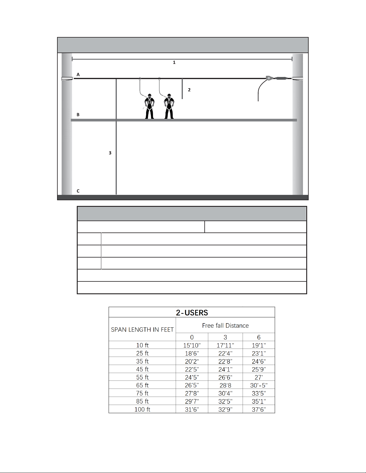
•The lifeline shall be installed higher than the shoulder to limit free fall to 6’ or less*. When using SRDs the lifeline must be positioned overhead. The
deceleration of the self retractable lifeline may be much longer as it declaimed when attach to a flexible anchorage attachment, please Only make sure
to use a self retractable lifeline that has anti-racheting design and will still function on this temporary horizontal lifeline.
•Do not alter or intentionally misuse this equipment.
•Consult PALMER SAFETY when using this equipment in combination with components or subsystems other than those described in this
manual.
•Do not connect rebar hooks, large carabiners, or large snap hooks to the FBH dorsal D-rings as this may cause a roll-out condition and/or
unintentional disengagement.
•Avoid sharp and/or abrasive surfaces and edges.
•Use caution when performing arc welding. Arc flash from arc welding operations, including accidental arcs from electrical equipment, can
damage equipment and are potentially fatal.
•Examine the work area. Be aware of the surroundings and workplace hazards that may impact safety, security, and the functioning of fall arrest
systems and components.
•Hazards may include, but are not limited to, cable or debris tripping hazards, equipment failures, personnel mistakes, or moving equipment
such as carts, barrows, fork lifts, cranes, or dollies. Do not allow materials, tools, or equipment in transit to contact any part of the fall arrest
system.
•Do not work under suspended loads.
•The use of independent HLL systems for each person or shorter span lengths or intermediate anchor points is recommended to minimize the
potential of the other workers falling.
IMPORTANT
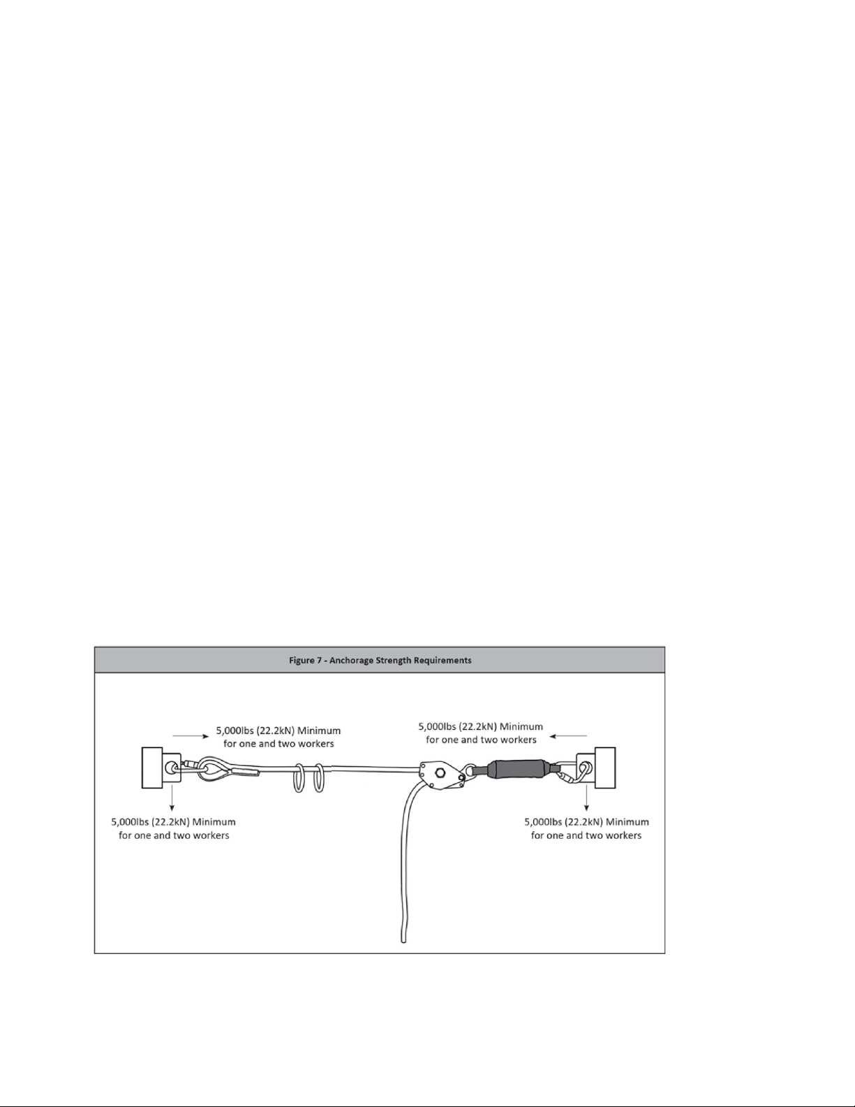
This product is part of a personal fall arrest, restraint, work positioning, suspension, or rescue system. A Personal Fall Arrest System (PFAS) is
typically composed of an anchorage and a Full Body Harness (FBH), with a connecting device, i.e., a Shock Absorbing Lanyard (SAL), or a
Compatible Self-Retracting Device (SRD) that has anti-racheting design, attached to the dorsal D-ring of the FBH.
These instructions must be provided to the worker using this equipment. The worker must read and understand the manufacturer’s instructions for
each component or part of the complete system. Manufacturer’s instructions must be followed for proper use, care, and maintenance of this
product. These instructions must be retained and be kept available for the worker’s reference at all times. Alterations or misuse of this product, or
failure to follow instructions, may result in serious injury or death.
A Fall Protection Plan must be on file and available for review by all workers. It is the responsibility of the worker and the purchaser of this
equipment to assure that users of this equipment are properly trained in its use, maintenance, and storage. Training must be repeated at regular
intervals. Training must not subject the trainee to fall hazards.
Consult a doctor if there is reason to doubt your fitness to safely absorb the shock of a fall event. Age and fitness seriously affect a worker’s ability
to withstand falls. Pregnant women or minors must not use this equipment.
ANSI limits the weight of fall protection equipment users to a maximum of 310 lbs. Products in this manual may have a rated capacity exceeding
ANSI capacity limits. Heavy users experience more risk of serious injury or death due to falls because of increased fall arrest forces placed on the
user’s body. In addition, the onset of suspension trauma after a fall event may be accelerated for heavyusers.
The user of the equipment discussed in this manual must read and understand the entire manual before beginning work.
NOTE: For more information consult the ANSI Z359 body of standards.

2.0
Application
2.1
The PALMER SAFETY 2-Person Temporary HLL provides horizontal mobility for workers exposed to fall hazards and is designed as an
anchorage subsystem for the attachment of up to two PFASs. The HLL is adjustable up to 100’ in length for a single span system and
is designed to be used as part of a complete PFAS. See Figure 1.
Figure 1 - About the 2-Person Temporary HLL
When properly tensioned, the lifeline will react to a fall event of up to two workers by combining the energy absorbing properties of the
lifeline energy absorber, the lifeline, and the worker’s personal energy absorber. During a fall event, the stretch of the lifeline and the
expansion of the user’s PFAS will result in reduced forces to the anchor and to the user’s body.
2.2
Application Limits: The PALMER SAFETY 2-Person Temporary HLL is a dynamic anchorage subsystem that will vary in its performance
depending upon the length of the system, the number of workers attached and the type of PFAS being used. Care should be taken to
understand the capacity of the system, minimum required fall clearance, anchorage strength requirements, total allowable free fall, total
allowable
fall clearance, and how the user’s PFAS will deploy during a fall event. Longer HLL spans will generate more lifeline deflection and sag
during a fall event and will result in greater clearance requirements. See Figure 2.
It is important to use intermediate anchor points which would significantly help to reduce the fall clearance space and also reduce the
other risks could happen.
A
Deployed In-Line Energy Absorber
E
Height of Worker
B
Dynamic Lifeline Sag
F
Safety Factor
C
Deployed EAL
G
Total Required Fall Clearance
D
D-ring Shift and Harness Stretch
H
Total SRD Deceleration Distance from User’s Manual*
A
Connectors
B
2-Person HLL Rope
C
O-Rings x2
D
Tensioner
E
Energy Absorber
Figure 2 - Clearance Requirements
B
A
A
B
A
A
G
C
D
B
D
H
F
B
C
D
G
G
D
G
H
E
E
F
F
F

2.3
System Capacity: The PALMER SAFETY 2-Person Temporary HLL maximum capacity is two workers simultaneously, with each worker
weighing no more than 310 lbs. inclusive of clothing, tools, etc.
2.4
Anchorage Requirements: End anchors selected for use with this system must be a minimum of 5,000 lbs. (22.2 kN) for one and two
workers. If used in applications with leading edge hazards, anchorage locations must be selected so that the deflected HLL shall not
come in contact with a leading edge in the event of a fall.
2.5
Total Allowable Free Fall: OSHA limits free fall to 6’ or less. The HLL system described in this manual is designed to be used overhead and
free fall should be limited to 6’ only.
2.6
PFAS Selection: Only PALMER SAFETY PFASs may be used in conjunction with this HLL system. The HLL may be used with
PALMER SAFETY energy absorbing lanyards those are ANSI Z359.13 complies and PALMER SAFETY fall arrestor connecting
subsystems.
2.7
Clearance Requirements: The PALMER SAFETY 2-Person Temporary HLL is designed to react to a fall event by elongating and deflecting
to absorb energy. PFAS attached to the HLL will also elongate during a fall event. Failure to calculate the fall clearance required when
using the system could result in contact with a lower level or obstruction during a fall event and could result in serious injury or death.
See tables and charts below for calculating minimum required fall clearance.
2.7.1 Minimum Required Fall Clearance for One Worker w/EAL
Temporary HLL with EAL Minimum Required Fall Clearance
310 lbs. Maximum User Capacity
Max. One Worker
1
Find Span Length in Table Below
2
Find Freefall Distance in Table Below
3
Required Fall Clearance at the intersection of Span Length and Freefall Distance (see table below)
A. Overhead Anchorage B. Walking/Working Surface C. Nearest Lower Level or Obstruction
* Work below HLL to avoid Swing Fall
Freefall Distance (feet)
Figure 3 - 2-Person Temporary HLL with EAL
Minimum Fall Clearance (One Worker)
1
A
2
B
3
C

2.7.2 Minimum Required Fall Clearance for Two Workers w/EAL
Temporary HLL with EAL Minimum Required Fall Clearance
310 lbs. Maximum User Capacity Each
Max. Two Workers
1
Find Span Length in Table Below
2
Find Freefall Distance in Table Below
3
Required Fall Clearance at the intersection of Span Length and Freefall Distance (see table below)
A. Overhead Anchorage B. Walking/Working Surface C. Nearest Lower Level or Obstruction
* Work below HLL to avoid Swing Fall
Figure 4 - 2-Person Temporary HLL with EALs
Minimum Fall Clearance (Two Workers)

Figure 6 - Incorrect Connections
WARNING
When a worker falls while connected to the horizontal lifeline, the system will deflect. If two or more workers are connected to
the same horizontal lifeline, and one worker falls, the other workers may be pulled off the walking-working surface. The
potential for the other workers falling increases as the lifeline length increases. The use of independent HLL systems for each
person or shorter span lengths or intermediate anchor points is recommended to minimize the potential of the other workers
falling.
2.8 Rescue: The PALMER SAFETY 2-Person Temporary HLL is part of a complete PFAS. It is not intended as a rescue device.
Use of this system presents a wide variety of potential rescue scenarios. Users of this system should understand their
work environment and develop a rescue plan accordingly. It is recommended that a trained on-site rescue team be
present during use of thesystem.
3.0 System Requirements
3.1 Anchorage Strength: End anchors selected for use with this system must have a minimum rating of 5,000 lbs. (22.2 kN) for one- and two-
worker applications.
3.2 Structure: The mounting points for the anchorage must be capable of supporting no less than 5,000 lbs. (22.2 kN) for one- and two-
worker applications, see Figure 7.
3.2
Compatibility of Connectors: Connectors are considered to be compatible with connecting elements when they have been designed to
work together in such a way that their sizes and shapes do not cause their gate mechanisms to inadvertently open regardless of how
they become oriented. Contact PALMER SAFETY if you have any questions about compatibility. Connectors must be compatible with
the anchorage or other system components. Do not use equipment that is not compatible. Non-compatible connectors may
unintentionally disengage. Connectors must be compatible in size, shape, and strength. Self-closing, self-locking snap hooks and
carabiners are specified by OSHA and ANSI Z359.12.
3.3
Compatibility of Components: Equipment is designed for use with approved components and subsystems only. Substitutions or
replacements made with non-ANSI Z359 compliant components or subsystems may jeopardize compatibility of equipment and may affect
the safety and reliability of the complete system. Ensure compatibility between the connectors if non- PALMER SAFETY components are
used for fall protection, see Figure 6.
3.4
Connectors: Only use self-locking snap hooks, rebar hooks, and carabiners with this equipment. Only use connectors that are suitable to
each application. Ensure all connections are compatible in size, shape and strength. Do not use equipment that is not compatible. Visually
ensure all connectors close and lock completely. Connectors (snap hooks, rebar hooks, and carabiners) are designed for use only
as specified in this manual.
A
Never connect two active components (snap hooks or carabiners) to each other.
B
Never connect two active components (snap hooks or carabiners) to a single D -ring at the same time.
C
Never connect in a way that would produce a condition of loading on the gate.
D
Never attach to a object in a manner whereby the gate (of the snap hook or carabiner) would be
prevented from fully closing and locking. Always guard against false connections by visually inspecting for closure and lock.
E
Never attach explicitly to a constituent subcomponent (webbing, cable or rope) unless specifically provided for bythe manufacturer’s instructions for
both subcomponents (snap hook or carabiner and webbing, cable or rope).
F
Never attach in a manner where an element of the connector (gate or release lever) may become caught on the anchor thereby producing
additional risk of false engagement.
G
Never attach a spreader snap hook to two side/positioning D-rings in a manner whereby the D-rings will engage the gates; the gates on a spreader
must always be facing away from the D-rings during work positioning.

4.0
Installation and Use
4.1
Plan the Personal Fall Arrest System (PFAS): Inspect the HLL subsystem before each use in accordance with the procedures detailed in
Section 6. Examine the work area and take action to address hazards. Falls are a serious hazard when working at height. Training and
equipment are the tools of fall hazard management. There are several closely related facets of fall hazard management with a PFAS;
•
Anchor Point Selection
•
Anchorage Connector
•
Deceleration Device
•Maximum Arrest Force
•Deceleration Distance
•Minimum Required Fall Clearance (MRFC)
•
Body Wear
•
Rescue
4.2
Anchor Point Selection: Select a suitable anchor point. Consider the area where the work is being performed. In an overhead anchorage
condition, the area below the anchorage is the work zone. Lateral movement away from the anchorage is hazardous. As distance from
the anchor increases, the work zone expands, and so does the hazard. Work zone expansion is measured in feet and has a direct influence
on user safety. Always work as close to the anchor as possible.
If used in applications with leading edge hazards, anchorage locations must be selected so that the deflected HLL shall not come in
contact with a leading edge in the event of a fall. For below D-ring anchor point installations for use with this HLL system, contact
PALMER SAFETY
4.3
Anchorage Connector: Anchorage Connectors used as part of a PFAS should be designed for use with specified anchor points and
compatible with the PFAS components and connectors to be used in the assembly of a complete PFAS. Care should be taken to ensure
proper assembly, installation and maintenance of all Anchorage Connectors to be used when planning a PFAS. Failure to inspect,
assemble, install and/or maintain Anchorage Connectors could result in injury or death.
4.4
Connectors/Deceleration Devices: Connectors and Deceleration Devices such as Shock Absorbing Lanyards, Self-Retracting
Devices/Lifelines, and Fall Arrestor Connector Subsystems (Vertical Lifeline/Rope Grab Combinations) are designed to connect the user’s
body wear to the Anchorage Connector and/or Anchor Point of a Personal Fall Arrest System.
4.5
Product Assembly and Installation: System installation requires end anchor points that are a minimum of 5,000 lbs. (22.2 kN) for one
and two workers, see Figure 8. The lifeline shall be installed higher above the shoulder to limit free fall to 6’ or less*. When using SRDs
the lifeline must be positioned overhead and the SRD must be have anti-racheting design. The horizontal lifeline should be positioned in a
manner to minimize free fall while allowing ease of use. Movement away from the lifeline should be limited to reduce the potential for
swing fall. Lifeline end anchors should be installed at approximately the same elevation so that the lifeline itself is not sloped more than 5
degrees.
Step 1: Determine the location of the end anchorages and, in accordance with Section 3.2, evaluate their strength. Determine the span
length of the system and determine the minimum required clearance for safe use in accordance with Section 2.7.
Step 2: Install the end anchorage connectors. The PALMER SAFETY 2-Person Temporary HLL system comes with 2 pass-through anchor
straps for wrapping around columns. If using pass through anchor straps, ensure strap is wrapped at least twice around the end
anchorage, see Figure 9. This will help prevent sliding of the anchor straps during use. If using alternative anchorage connectors, please
ensure the connectors are compliant and conform to the requirements of Section 3.2. Not all anchorage connectors are designed for use
with horizontal lifeline systems. In all cases, refer to the user’s instruction manual for the end anchorage connectors to be used.

Step 3: Secure the HLL system to the anchorage connectors with the provided end attachment carabiners.
Step 4: Close the locking lever into the down position so that it is engaged; Figure 9A. Remove the slack from the line by pulling the
preinstalled rope through the tensioner by hand, see Figure 9B . Insert a pointed bar through the tensioning nut or use a wrench to
tighten by turning the nut clockwise until the tensioner slips or can no longer rotate, see Figure 10. Do not alter the tensioner to
achieve greater tension. Final line tension will be approximately 200 - 300 lbf. The loose end tail length should not less than 3.3ft
(1.0m)
Step 5: Once properly tensioned, connect a PFAS system only to the connection O-rings that have been preinstalled on the lifeline.
4.6
Releasing Lifeline Tension: Upon completion of work, to move to a new work location or to disconnect from the end anchorage
connectors lifeline tension should be released. Torelease lifeline tension:
Step 1: Lift the locking lever and position the pointed bar or wrench between the tensioner body and locking lever.
Step 2: Pry upward with the pointed bar or wrench to disengage the lock lever and release the HLL tension, see Figure 11A.
Step 3: Loosen the tensioning nut with the pointed bar or wrench by turning the tensioning nut counter clockwise until loose, see
Figure 11B
Step 4: If necessary, the rope can be pulled through the tensioner by hand while holding the locking lever in the disengaged
position, see Figure 11C.
B
A
Figure 9- Removing Slack
Figure 10 - Tensioning
C
B
A
Figure 11 - Releasing Lifeline Tension

5.0 Maintenance, Service and Storage
Maintenance: Clean the horizontal lifeline with water and mild detergent. Do not allow excessive build-up of dirt, paint or other agents that
may cause damage or hardening of the rope fibers. Do not treat the lifeline with heat to dry or clean the lifeline. Hardening of
the ropes fibers from external elements may result in a loss of strength or alter the properties of the rope in a manner that
could cause the HLL to fail to operate or perform properly.
Service: There are no specific service requirements for this system component.
Storage: The system should be stored in its carry bag and kept out of direct sunlight. Store in a clean, dry and chemical freeenvironment.
6.0 Materials:
Rope:Double braided polyester
Energy absorber: Polyester webbing
Connectors: Steel
Tension adjuster: Steel & Aluminium
7.0Inspection
1.
Pre-Use Inspection: Prior to each use the HLL system should be inspected by the user for damage, wear and to ensure the lifeline is
properly tensioned. Please review the inspection checklist for inspection requirements.
2.
Inspection Frequency: Other than pre-use inspection, the PALMER SAFETY 2-Person Temporary HLL should be inspected by a competent
person at least once a year.
3.
Inspection Checklist: A general inspection should be done at the intervals specified in this manual. Inspect asfollows:
Step 1: Inspect labels. Ensure legibility of content. If labels are missing or illegible, remove the system from service.
Step 2: Inspect all metal components for cracks, corrosion, deformities, missing parts or noticeable defects. Metal components include
O-rings, carabiners, thimble eyes, rope tensioner, D-rings, ferrules etc.
Step 3: Inspect rope for wear, paying special attention to the areas of rope most likely in contact with the tensioner teeth. Rope should
not present frayed strands, cuts, abrasions, burn marks, and discoloration indicating UV damage.* Thimble eyes should be firmly in place
and there should be no build-up of foreign matter such as paint, dirt, rust, concrete or cement etc.
*Minor fuzziness of rope of rope is acceptable so long as the inner white core of the rope is not openly exposed.
4.
Inspection Results: Inspection results should be recorded by a competent person at least once a year.
5.
Inspection Document: Record inspection results on the inspection record provided below, or similardocument.

Inspection Record
Model #: Serial #: Date ofManufacture:
INSPECTION
DATE
INSPECTOR
COMMENTS
PASS/FAIL
CORRECTIVE ACTION NEEDED
APPROVED BY

7.0 Labels
The labels must be present and legible.

GENERAL WORK PRODUCTS LLC | 6000 Jefferson Hwy, Harahan,LA 70123
Table of contents
Other Palmer Safety Safety Equipment manuals