Palmer Safety A60160 User manual

•Fall Protection •Training •Netting •PPE
®
INSTRUCTION MANUAL
CABLE HORIZONTAL LIFELINE SYSTEM
These Instructions Apply to the Following Model(s):
A60160 (60’), A100160 (100’)

2
General Work Products LLC | 6000 Jefferson Hwy | Harahan, LA 70123 www.PalmerSafetyUS.com
•Fall Protection •Training •Netting •PPE
®
IMPORTANT:
Do not skip this instruction manual. Read the instruction manual carefully before using the equipment. Failure to do so
may cause serious injury or death. These instructions serve as the Manufacturer’s Instructions and are to be used as part
of an employee training program for the system, as required by OSHA.
Table of Contents
Overview........................................................................................................................................................2
Safety Standards ............................................................................................................................................2
Worker Denitions.........................................................................................................................................2
Applications ...................................................................................................................................................3
Limits .............................................................................................................................................................3
Components and Specications .....................................................................................................................7
Installation and Use .......................................................................................................................................7
Adjustment.....................................................................................................................................................7
Maintenance, Cleaning, and Storage .............................................................................................................8
Inspection.......................................................................................................................................................8
Inspection Log ...............................................................................................................................................9
Safety Information .......................................................................................................................................10
Overview
You have just purchased your very own Palmer Safety Fall Protection Cable Horizontal Lifeline System (Cable HLL).
This manual must be read and understood in its entirety, whereas any specied training course on fall protection can be
utilized to provide the necessary knowledge.
All of these instructions need to be made available to the user of the equipment. The user needs to understand how
the Cable HLL works and how to use it safely. They also need a basic understanding of fall safety equipment used in
combination with the Cable HLL, such as harnesses and cables.
Safety Standards
All applicable OSHA 1926 Subpart M, OSHA 1910, ANSI Z359.6-2016, and ANSI A10.32-2012 standards for fall
protection are followed when this product is used as instructed. Standards are regulated depending on the type of work
being done. You can review of all regulations at regulatory agencies for more information on fall protection systems,
including any of the state-specic regulations.
Worker Denitions
NOTE: It is important to know the denition of those who work near or who may be exposed to fall hazards.

3
General Work Products LLC | 6000 Jefferson Hwy | Harahan, LA 70123 www.PalmerSafetyUS.com
•Fall Protection •Training •Netting •PPE
®
Qualied Person: A person with accreditation for this position who has sufcient experience or standing in their industry.
They are responsible for reviewing the effectiveness of fall prevention and rescue procedures.
Competent Person: A fall safety coordinator is a person who has been trained to manage all aspects of a company’s fall
safety program. This includes the actual regulation, the management thereof and its application. A person tasked with
identifying existing or foreseeable hazards. They have the power to temporarily stop work to address any concerns they
might have.
Authorized Person: An employee who’s area of responsibility includes areas where potential or existing fall hazards
exist. These employees need to be trained to understand what it takes to work safely around these hazards.
Qualied or Competent person on jobsite is responsible for training and inspection of HLL system. Please contact
your local Palmer Safety Specialist if you have questions or need training. We can provide training on the jobsite.
Applications
WARNING: Using the equipment in ways other than its intended purpose may result in severe injury or death. Maximum
1 attachment per connection point.
Fall Arrest: The Cable HLL System, which can be used in Personal Fall Arrest (PFAS) applications, will hold up to
two people at a time when used with the appropriate supporting structure. The supporting structure must also withstand
loads applied in the advised directions of at least 5000 lbs. Maximum freefall height is 6 feet, or up to 12 feet when in
combination with a harness that has been tested for such use. The D-ring needs to be in the dorsal position.
Restraint: The Cable HLL can be utilized in Restraint systems. Restraints are used to ensure workers do not get too close
to the edge of any fall hazards. Up to 4 people can use a single Cable HLL System at a time when working in restraints.
Make sure to account for the full length of the lanyard or SRL that you plan on using. The structure needs to guarantee
that it can withstand loads that are at least 1,000 lbs in every direction. No item shall be allowed to fall without restraint.
Restraint systems can only be used on surfaces where slopes are up 4/12.
D-rings that can used: Dorsal, Chest, Side, Shoulder.
TOTAL user weight capacity range (including person, clothing, tools, and equipment) is 130-420 lbs.
Limits
Fall Clearance: There should be enough clearance below the anchorage connector to arrest a fall before the person strikes
the ground or an obstacle. When guring out how far people might fall, there needs to be a safety buffer of 2 feet. People
also need to consider the distance they are slowing down at, how tall they are, the length of their lanyard or SRL. They
should also think about harness stretch and any other factors that apply.
Diagram shown below is a fall clearance calculation EXAMPLE ONLY.

4
General Work Products LLC | 6000 Jefferson Hwy | Harahan, LA 70123 www.PalmerSafetyUS.com
•Fall Protection •Training •Netting •PPE
®
Work Surface
Anchor Point
Free Fall Distance
Work Surface
DEFLECTION What’s the length of your HLL span?
39.05”
SPAN =
DEFLECTION = 94.83”
10’
52.01”
20’
62.18”
30’
71.00”
40’
86.99”
60’
79.14”
50’ 70’
102.89”
80’
111.35”
90’
120.38”
100’
Clearance data determined based on HLL level with harness dorsal D-ring (from a standing working position).
Always account for additional free fall if HLL is below dorsal D-ring.
TOTAL FALL CLEARANCE = DEFLECTION + FREE FALL + DECELERATION + STRETCH + SAFETY MARGIN + SWING FALL
Anchor Point
Cable HLL System with 6” Sag
Lifeline Deflection
Harness Stretch (1.5’)
Deceleration Distance
Swing Fall (If Applicable)
Safety Margin (2’)
Compatibility: To avoid interference when connecting Cable HLL Systems, there must be enough space between the
hook and its attachment point. This is known as “rolling out” and can cause the gate on the hook to inadvertently open
and release. All cables must be compatible with Cable HLL and must be approved by a Competent Person. All connectors
should be self-closing and self-locking, and should withstand a minimum load of 3,600 lbs.
C.
B.
A. F.
E.
D.
A. Two or more connectors should never be attached to a single D-ring.
B. Never attach a connector that could result in a load on its gate.
C. Connectors should not be connected in a false engagement. It should be visually conrmed that the connector
is fully engaged to the anchor point. Avoid conditions that allow for features that protrude from the connectors to
catch on the anchor, giving a false sense of being connected.
D. Connectors should not be connected to each other.
E. Connectors should not be connected directly to the webbing or to the rope lanyard or tie back, unless
specically allowed by the manufacturer.

5
General Work Products LLC | 6000 Jefferson Hwy | Harahan, LA 70123 www.PalmerSafetyUS.com
•Fall Protection •Training •Netting •PPE
®
F. Connectors should not be connected
to any object which does not allow the
connector gate to close or lock. Anchor
shapes that allow roll out to occur should
never be used for connection. If the anchor,
to which the snap hook or carabiner is
attached, is under sized or irregular in
shape, then this may allow for the gate of
the connector to come in contact with the
anchor, thereby causing the connector to
open up and possibly disengage from the
anchor. This is known as roll out of the
connector. See Diagram 2.
G. Do not use connectors on an anchorage object as shown in gure A to F.
Correct Anchorage Positioning: This chart details allowable working zones required to reduce risk of swing falls and
improper side loading. ALWAYS adhere to information specied by chart.
This chart details allowable working zones required to reduce risk of swing falls and improper side loading. ALWAYS
adhere to information specied by chart.
Anchor Distance
From Leading
Edge (Y)
Working Distance
Along Roof Edge
(Either Direction) (X)
Working
Angle From
Perpendicular (Ø)
6’ 8’ 53°
10’ 9’ - 9” 45°
15’ 11’ - 7” 38°
20’ 13’ - 3” 33°
25’ 14’ - 6” 30°
30’ 16’ 28°
35’ 17’ - 2” 26°
40’ 18’ - 3” 24°
45’ 19’ - 4” 23°
50’ 19’ - 10” 21°
55’ 21’ - 4” 21°
60’ 22’ - 3” 21°
Ø: Total Working Angle
X: Working Distance
Along Leading Edge
Y: Distance From
Leading Edge
X
Y
ø
X
Leading Edge
For example, if the anchorage connector is 6’ from the leading edge (Y), the working distance (X) is 8’ in each direction
from the perpendicular, which translates to a 53° working angle.
Swing Falls: When using or installing any anchors, think about eliminating swing fall hazards. Swing falls happen when
the anchor point is not directly over the object being secured. Always make your anchors as close to perpendicular to
where you are securing something as possible. Swing falls can increase the chances of serious injury or death if there is a
fall.
As displayed in the following diagrams, there are danger zones when using a single HLL, and in order to be safe use
multiple HLLs.
2. The gate presses against
the connecting Ring.
Small ring or other non-compatibly shaped element
3. The gate opens allowing
the snap hook to slip off.
1. Force is applied to
the snap hook.
Diagram 2 - Unintentional Disengagement (roll-put)

6
General Work Products LLC | 6000 Jefferson Hwy | Harahan, LA 70123 www.PalmerSafetyUS.com
•Fall Protection •Training •Netting •PPE
®
Safe Attachment Zone
DANGER ZONES:
Work in this areas
NOT allowed.
Horizontal Lifeline
100’
120’
60’
Horizontal Lifeline
Place HLL 6’-10’ Back
from Leading Edge
120’
60’
Safe Attachment Zone
Extends for Entire
Building Roof Perimeter

7
General Work Products LLC | 6000 Jefferson Hwy | Harahan, LA 70123 www.PalmerSafetyUS.com
•Fall Protection •Training •Netting •PPE
®
Components and Specications
Components made from some or all of the following: galvanized steel and stainless steel.
Components Included:
A. 6’ Vinyl coated cable choker – Pieces (2)
B. Assembled 3/8” Cable HLL System with pull loop
on one end – Pieces (1)
C. 3/8” Adjustable cable clamps – Pieces (3)
D. Military grade backpack
Tools Needed:
1.) 5/16” wrench
2.) 3/4” wrench
Requirements:
1.) Two (2) 5,000 lb. (HLL Compatible) anchor points
2.) Weight Min / Max (120 lbs. – 420 lbs.)
3.) Maximum Users – Two (2)
4.) 0 – 60’ (1 Absorber)
5.) 0 – 100’ (2 Absorbers)
Installation and Use
1.) Conrm with Competent Person that anchor points are rated for 5,000 lbs.
2.) Measure distance between anchor points. Set the clamps to measured distance.
3.) Make sure turnbuckle is all the way extended.
4.) Attach carabiner on pull loop end to rst anchor point.
5.) Attach carabiner on end with cable clamps to second anchor point.
6.) Tighten turnbuckle until line has between 2 - 6 inches of slack.
Adjustment
Efciency ratings for wire rope end terminations are based upon the catalog breaking strength of wire rope. The efciency
rating of a properly prepared loop or thimble-eye termination for clip sizes 1/8” through 7/8” is 80%, and for 1” through
3-1/2” is 90%.
WARNING: Prepare wire rope end termination only as instructed. DO NOT use vinyl/plastic coated wire rope. Apply
rst load to test the assembly. This load should be of equal or greater weight than loads expected in use.
A
B
D
C

8
General Work Products LLC | 6000 Jefferson Hwy | Harahan, LA 70123 www.PalmerSafetyUS.com
•Fall Protection •Training •Netting •PPE
®
1. Refer to Torque Table in following these instructions. Turn
back specied amount of rope from thimble or loop. Apply rst
clip one base width from dead end of rope. Use torque wrench
to evenly tighten clip, alternating from one nut to the other until
reaching the recommended torque.
2. When two clips are required, apply the second clip as near the
loop or thimble as possible. Use torque wrench to evenly tighten
clip, alternating until reaching the recommended torque. When
more than two clips are required, apply the second clip as near
the loop or thimble as possible, turn nuts on second clip rmly,
but do not tighten.
3. When three or more clips are used, space additional clips
equally between rst two. Take up rope slack, use torque wrench
to tighten on each clip evenly, alternating from one nut to the
other until reaching recommended torque.
4. O-rings and sliders: Palmer Safety provides (2) 2-1/2”
O-rings that should be applied to the cable lifeline to allow
compatible attachment of snap hooks and other connecting devices. O-rings and sliders must be attached to the lifeline
before the system is complete.
For systems with multiple intermediate anchor points or for any other questions, contact Palmer Safety Fall Protection.
Maintenance, Cleaning, and Storage
If Cable HLL System fails inspection in any way, immediately remove it from service, and contact Palmer Safety to
inquire about its return or repair.
Cleaning after use is important for maintaining the safety and longevity of Cable HLL System. Remove all dirt,
corrosives, and contaminants from Cable HLL System before and after each use. If Cable HLL System cannot be cleaned
with plain water, use mild soap and water, then rinse and wipe dry. NEVER clean Cable HLL System with corrosive
substances.
When not in use, store equipment where it will not be affected by heat, light, excessive moisture, chemicals, or other
degrading elements.
Inspection
1.) System should be inspected before each use.
If any damage is found or system is involved in a fall remove from jobsite immediately.
2.) System should be inspected by a Competent Person at a minimum of every 6 months.
3.) All inspections should be documented.
Palmer Safety would be glad to help with any inspections.
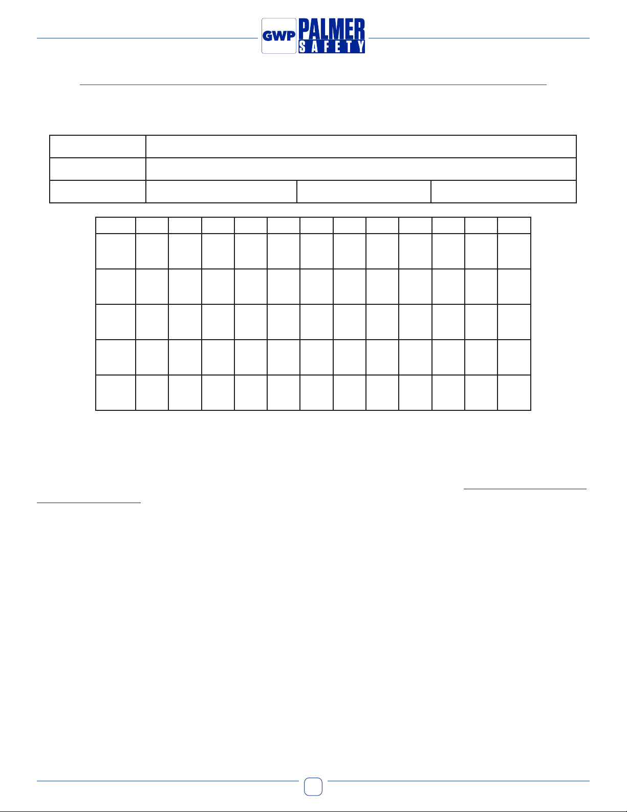
Torque Table
Clip Size
(in.)
Rope Size
(in.)
Minimum #
of Clips
Amount of Rope to
Turn Back (in.)
Torque
(ft. lbs.)
3/16 3/16 2 4 30
1/4 1/4 2 4 30
5/16 5/16 2 5 30
3/8 3/8 2 5¼ 45
7/16 7/16 2 6½ 65
1/2 1/2 3 11 65
9/16 9/16 3 12¾ 130
5/8 5/8 3 13½ 130
3/4 3/4 3 16 225
7/8 7/8 4 26 225
1 1 5 37 225
11/8 11/8 5 41 360
1¼ 1¼ 6 55 360
13/8 13/8 6 62 500
1½ 1½ 7 78 500
1½ 1½ 7 78 500
If greater number of clips than shown are used, amount of turn-back
should be increased proportionately. Torque values shown are based
upon the threads being clean, dry, and free of lubrication.

9
General Work Products LLC | 6000 Jefferson Hwy | Harahan, LA 70123 www.PalmerSafetyUS.com
•Fall Protection •Training •Netting •PPE
®
Inspection Log
SERIAL NUMBER:
MODEL NUMBER:
DATE PURCHASED: DATE OF FIRST USE:
J F M A M J J A S O N D
YR
YR
YR
YR
YR
Product lifetime is indenite as long as it passes pre-use and Competent Person inspections. User must inspect prior to
EACH use. Competent Person other than user must complete formal inspection at least every 6 months. Competent Person
to inspect and initial.
This inspection log must be specic to one Cable HLL System. All inspection records must be made visible and available
to all users at all times.
If equipment fails inspection or is involved in a fall REMOVE FROM SERVICE IMMEDIATELY.

10
General Work Products LLC | 6000 Jefferson Hwy | Harahan, LA 70123 www.PalmerSafetyUS.com
•Fall Protection •Training •Netting •PPE
®
INSPECTION DATE INSPECTION ITEMS NOTED CORRECTIVE ACTION MAINTENANCE PERFORMED
Approved by:
Approved by:
Approved by:
Approved by:
Approved by:
Approved by:
Approved by:
Safety Information
WARNING: Failure to understand and comply with safety regulations may result in serious injury or death. Regulations
included herein are not all-inclusive, are for reference only, and are not intended to replace a Competent Person’s
judgment or knowledge of federal or state standards.

11
General Work Products LLC | 6000 Jefferson Hwy | Harahan, LA 70123 www.PalmerSafetyUS.com
•Fall Protection •Training •Netting •PPE
®
Notes:

Manual Revision: 230301
General Work Products LLC
6000 Jefferson Hwy
Harahan, LA 70123
(504) 733-1808
www.PalmerSafetyUS.com
•Fall Protection •Training •Netting •PPE
®
This manual suits for next models
1
Table of contents
Other Palmer Safety Safety Equipment manuals