manuals.online logo
Brands
  1. Home
  2. •
  3. Brands
  4. •
  5. Palram
  6. •
  7. Tent
  8. •
  9. Palram Juniper 3x2 Extension User manual

Palram Juniper 3x2 Extension User manual

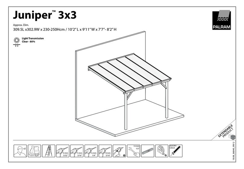
JuniperTM 3x2 Extension
18.12_86042_MV-2
Approx. Dim.
183 L x 302.9 W x 230-250 H cm / 6’ L x 9’11”W x 7’7”- 8’2” H
3x2 Ext.
EXTENDABLE
PRODUCT
x2
8 mm
5/16”
6 mm
1/4”
5 mm
3/16”
SILICON \
CAULK
4 mm
5/32”
13 mm
1/2”
Light Transmission
Clear - 80%
Snow Load
24.6lbs/ft
120kg/m
2m / 6’ 3m / 10’ 4m / 12’3”
5m / 16’3” 5.5m / 18’5” 6.8m / 22’5”
7.4m / 24’6” 8.6m / 28’6”
Index
Extending the Patio Cover - 3 Meters Depth
2m Ext. / 6’2m / 6’ 3m / 10’
2m Ext. / 6’7”
3m / 10’
2m Ext. / 6’
2m Ext. / 6’
2m Ext. / 6’ 2m Ext. / 6’ 2m Ext. / 6’
3m / 10’
3m / 10’
2m Ext. / 6’
2m / 6’
2m / 6’
3m / 10’
2m Ext. / 6’
2m Ext. / 6’
2m Ext. / 6’
2m / 6’
2m Ext. / 6’
2m Ext. / 6’
2m / 6’
AFTER SALE SERVICE
palramapplications.com/after-sales-service
LOCATIONS
USA
England
France
Germany
International
customer.service@palram.com
customer.serviceUK @palram.com
customer.serviceFR@palram.com
customer.serviceDE @palram.com
customer.service@palram.com
www.palramapplications.com
877-627-8476
01302-380775
0169-791-094
0180-522-8778
+972 4-848-6816
0ConcreteFoundation:
use suitable screws and plugs.
(Screws and plugs are not supplied).
® Wood Foundation:
Use suitable fasteners for wood (not supplied), screw them
into the wood for a minimum depth of 6 cm (2.4 in.)
0Soil Foundation:
Dig holes sized 40/40/40 cm (15.8/15.8/15.8 in.) into the
ground, and fill with concrete, see relevant drawing.
use suitable screws and plugs.
(Screws and plugs are not supplied).
*For frozen areas, please checkthe required depth needed
for these holes.
For any other type of hard surface / foundation:
Please consult with an expert regarding which fasteners are
suitable for your type offoundation.
Important! The poles position can be adjusted during the
installation.The poles' positioning is flexible, enabling you to
set their distance from the house and between the poles at
the front.
OD
Foundation
0Betonfundament: CD
mittels anmessener Schrauben und Dubeln.
(Schrauben und Dubel sind nicht mitgeliefert).
0Holzfundament:
Verwenden Sie geeignete Befestigungen fur Holz (nicht
mitgeliefert), schrauben Sie diese mit einer Mindesttiefe von
6 cm in das Holz (2.4 in.)
0Bodenfundament:
Graben Sie ein Fundamentloch von 40/40/40 cm
(15,8/ 15,8 in) in den Boden und fullen Sie diese mit Beton,
siehe entsprechende Zeichnung.
mittels anmessener Schrauben und Dubeln.
(Schrauben und Dubel sind nicht mitgeliefert).
*Bitte berucksichtigen Sie bei gefrorenen Flachen die
notwendigeTiefe fur die Locher
Fur jede beliebige Oberflache/Fundament:
Bitte wenden Sie sich in Bezug auf die
Befestigungselemente, die fur lhre Fundamentart geeignet
sind, an einen Fachmann.
Wichtig! Die Position der Saulen kann wahrend des Einbaus
eingestellt werden. Die Positionierung der Saulen ist flexibel,
sodass Sie den Abstand zwischen dem Haus den Saulen auf
derVorderseite einstellen konnen.
0Fondation en beton : CD
utilisez des vis et des chevilles adaptees. (Les vis et les
chevilles ne sont pas fournies).
0Fondation en bois :
Utilisez des fixations appropriees pour le bois (pas fournies).
Fixez-les dans le bois sur une profondeur minimale de 6 cm
(2,4 po).
0Fondation au sol :
Creusez des trous de 40x40x40 cm (15,8x15,8x15,8 po)
dans le sol, puis remplissez-les de beton (voir le schema
correspondant).
utilisezdes vis et des chevilles adaptees. (Les vis et les
chevilles ne sont pas fournies).
*Pour les zones gelees, veuillez verifier la profondeur
necessaire requise pour ces trous
Pour tout autre type de surface dure / fondation :
Veuillez consulter un expert quant aux fixations compatibles
a votre type de fondation
Important! La position des poteaux peut etre ajustee au
moment de ('installation. Le positionnement des poteaux
est flexible, ce qui vous permet de les installer a distance de
votre maison ou entre les poteaux situes a ('entree.
Min.
6 cm
2.36"
Please read these instructions carefully before you start to assemble this product.
Please carry out the steps in the order set out in these instructions.
Keep these instructions in a safe place for future reference.
General Information
Assembly must be done within 15 days at most. Otherwise, the product should be safely
stored to maintain its quality.
The natural wood parts will vary according to the weather conditions and its exposure.
They will slightly swell during winter time and retract at summer time. These changes are
normal and do not affect the product's strength, stbility and functionality.
Care and Safety Advice
Having purchased a long patio cover, make sure you received all boxes according to the
additional page (Extending your patio cover) on the instruction manual.
As soon as you are ready to assemble your patio cover (you can start with this box),
sort the parts and check in accordance with the content list.
For safety purposes we strongly recommendthe product to be assembled
by at least two people.
Some parts may have sharp edges. Please be careful when handling components.
Always wear gloves, eye protection, and long sleeves when assembling or performing any
maintenance on your product.
Do not attempt to assemble the product in windy or wet conditions.
Dispose ofall plastic bags safely - keep them out of reach of small children.
Keep children away from the assembly area.
Do not attempt to assemble the product ifyou are tired, have taken drugs,
medications or alcohol, or ifyou are prone to dizzy spells.
When using a stepladder or power tools, make sure you follow the manufacturer's safety
advice.
Do not climb or stand on the roof.
Heavy articles should not be leaned against the poles.
Do not hang or lay on the profiles & wooden beams.
Keep roof and gutter clearof snow, dirt & leaves.
Heavy snow load on roof can damage the product, making it unsafe to stand below
or nearby.
This product was designed to be used mainly as a Patio cover.
Products made of raw wood must be treated with insecticide and fungicide treatments.
The autoclave (green or brown) treated products do not need to be treated a second
time. Small spots may appear on the wood due to the autoclave treatment, these do not
impair the woods quality and durability. You can brush the wood with a soft brush to
help obscure the stains, however, these will fade it time with rain and the sums UV rays.
Before Assembly
This product must be assembled on a solid base (such as concrete, asphalt etc.)
and anchored to the surface ofyour choosing.
Choose your site carefully before beginning assembly.
Sort the parts and check according to the content part list.
Site surface needs to be leveled (mainly below the poles).
Please consult your local authorities if any permits are required prior to constructing
the product.
Make sure you have all the parts / screws / plugs required for the product's assembly
ready at hand before starting.
MWhen encountering the information icon, please refer to the relevant
assembly step for additional comments and assistance.
0 During Assembly
Use a plarform belowthe parts and assembly surface to avoid scratches and damages.
Product dimensions can be adjusted to your specific needs:
1.The wall-mounting profile (top-back)can be adjusted from 230 to 250 cm (90.6" to 98.4") above ground.
The adjusting is done when measuring and drilling (Step 5).
Please note the installation recommendations' height suggested in Diagram A.
Please note that the product appearance may slightly change as a result.
2. Poles distance from the side edges can be adjusted from 0 to 25 cm (0" to 9.8") as suggested in Diagram B1.
The adjusting is done when measuring and drilling (Step 2).
3. Poles distance from the wall can be adjusted from 250 to 279 cm (98.4" to 109.8") as suggested in Diagram B2.
4. Wall mounting and distance from the wall determine the roof angle and the total depth of the product (distance
of gutter from the wall). Higher wall mounting and shorter distance between wall and poles increase the roof angle
and shorten the total depth as suggested in Diagram C.
aieps
Step 1: Product dimensions can be adjusted in accordance with the provided measurements.
If you wish to adjust the poles' distance from the wall, the measure given is Step 6 will need to be
adjusted accordingly, see comment is Step 6.
Step 2: Do not tighten the screws in order to avoid stripping and allowadjusting ofthe structure.
The wood pole should be attached at the juncture of the frontal wood beams.
Step 5: Please attach to the wall, use suitable screws and plugs for your wall type.
Screws and plugs are not supplied.
Step 6: If you wish to set the poles closer to the wall - adjust the measurement on Drawing B according
to the measure you take once the poles are set and leveled in their designated place. Use the same
measurement throughout the assembly.
Make sure you drill half-wayinto the wood beam's narrow facet.
Step 7: According to the number of extensions, a change in the drilling may be required at this stage.
Depending on whether numberof beams is even or odd. See differences in Step 10. in this case you may
have surplus parts.
Step 11: Attach to the surface ofyour choosing in Drawing C. Use suitable screws and plugs.
Screws and plugs are not supplied.
Step 15 Please apply silicone sealants above profile # # 8610+8611, in order to prevent water seepage.
Make sure the supplied screws and plugs are suitable for your wall type.
Step 16: Please note you install the panels with the UV protected side out
(marked with «THIS SIDE OUT») and peel the film strip covering the panels.
Step 19: Drill throught the aluminum profile using a 4mm drill bit,
do not drill into the wood beams!
*Tighten all screws when completing assembly, make sure to avoid stripping.
Note
The roof anchoring kit supplied with this product is suitable for concrete or solid brick
walls only.Other wall types need an accordant wall fixation kit.
10 cm 96.5 cm 96.5 cm 96.5 cm 10 cm
3.9" 37.9" 37.9" 37.9" 3.9"
A
230 - 250 cm
90.5 - 98.4"
A
E0
0
250 - 279 cm
98.4 - 109.8'
coc3
Lr? 0-25 cm
0-9.8" 0-25 cm
0-9.8"
Bitte lesen Sie diese Hinweise sorgfaltig, bevor Sie mit der Montage dieses Patio-
Abdeckungsystems starten.
Bitte fuhren Sie die Schritte in der Reihenfolge aus, wie sie in dieser Anleitung vorgegeben
sind. Bewahren Sie diese Anleitung an einem sicheren Ort auf.
Allgemeine Informationer
Die Montage muss innerhalb von maximal 15 Tagen erfolgen. Andernfalls sollte das Produkt sicher
aufbewahrt werden, um seine Qualitat zu erhalten.
Die naturlichen Holzteile variieren je nach Witterung und Belichtung. Sie werden im Winter leicht
anschwellen und sich im Sommer einziehen. Diese Erscheinungen sind normal und beeinflussen
nicht die Starke, Stabilitat und Funktionalitat des Produkts.
Pflege und Sicherheitshinweise
Achten Sie bitte nach I hrem Kauf der langenTerrassen-Abdeckung darauf, dass Sie alle Boxen gemaB
der zusatzlichen Seite der Anleitung (Verlangerung IhrerTerrassen-Abdeckung) erhalten haben.
Sobald Sie bereft sind, IhreTerrassen-Abdeckung zu installieren (Sie konnen mit dieser Box
anfangen), sortieren Sie die Teile und Oberprufen Sie, ob sie mit der Inhaltsliste Obereinstimmen.
Sortieren Sie die Teile und Oberprufen Sie die Inhaltsliste.
Aus Sicherheitsgrunden empfehlen wir dringend, dass das Produkt von mindestens zwei Menschen
zusammengebaut wird.
EinigeTeile haben Metallkanten.Bitte seien Sie vorsichtig beim Umgang mit den Komponenten.
Tragen Sie immer Handschuhe, Schuhe und Schutzbrille bei der Montage.
Versuchen Sie nicht, das Produkt bei windigen oder nassen Bedingungen zu montieren.
Entsorgen Sie alle Plastiktuten sicherheitsgemaB - bewahren Sie sie auBerhalb der Reichweitevon
kleinen Kindern auf.
Halten Sie Kinder vom Montagebereich fern.
Versuchen Sie nicht ein Produkt zusammen zu bauen, wenn Sie mude sind, Drogen, Medikamente oder
Alkohol genommen haben, oder wenn Sie zu Schwindelanfallen neigen.
Bei Verwendung einer Stehleiter oder Elektrowerkzeugen,stellen Sie sicher,
dass Sie die Sicherheitshin weise und Anweisungen des Herstellers befolgen.
Steigen oder stehen Sie nicht auf dem Dach.
Schwere Gegenstande durfen nicht an den Polen angelehnt werden.
Nicht an Profile & Holzbalken hangen oder darauf legen.
Halten Sie Dach - und Dachrinne frei von Schnee, Schmutz und Blattern.
Schwere Schneelasten auf dem Dach konnen das Produkt, beschadigen und das Darunter- oder
Danebenstehen gefahrlich machen.
Dieses Produkt wurde gestaltet, um hauptsachlich als terrassenabdekkung ben utzt zu werden.
Produkte aus Rohholz mussen mit lnsektizid- und Fungizidbehandlungen behandelt werden.
Die im Autoklaven (grun oder braun) behandelten Produkte mussen kein zweites Mal behandelt
werden. Durch die Autoklavierung konnen kleine Flecken auf dem Holz entstehen, welche
die Qualitat und Haltbarkeit des Holzes nicht beeintrachtigen. Sie konnen das Holz mit einer
weichen Burste bursten, um die Flecken zu verschleiern, diese verblassen jedoch auch mit der Zeit
aufgrund von Regen und UV-Strahlen der Sonne.
Vor dem Aufbau
Dieses Produkt muss auf einer festen Unterlage (wie Beton, Asphalt usw.)
montiert und auf dergewunschten Oberflache verankert werden.
Wahlen Sie lhren Standort sorgfaltig, bevor Sie mit dem Aufbau beginnen.
Sortieren Sie die einzelnen Teile und gleichen Sie sie mit der Inhaltsliste ab.
Die Aufbauflache muss geebnet werden (vor allem unter den Pfosten.
Bitte informieren Sie sich bei den ortlichen Behorden, ob fur den Aufbau des
Produktes eine Genehmigung erforderlich ist.
Bitte vergewissern Sie sich bevor Sie mit dem Aufbau beginnen, dass alle Teile/
Schrauben/ Stecker, die fur die Montage benotigt werden, auch vorratig sind.
Beim Aufbau wird lhnen das Informationssymbol begegnen.
Fur zusatzliche Kommentare und Unterstutzung beziehen Sie
sich bitte auf die entsprechende Aufbaustufe.
Hinweise wahrend der Montage
Verwenden Sie eine Platte unterhalb der Teile und der Montageflache, urn Kratzer und Beschadigungen
zu vermeiden.
ProduktmaBe konnen an lhre spezifischen Bedurfnisse angepasst werden:
1. Das Wandmontageprofil (Vorne-Hinten)kann von 230 bis 250 cm (90,6 bis 98,4 Zoll) Ober dem Boden reichen.
Die Anpassung erfolgt beim Messen und Bohren (Schritt 5).
Bitte beachten Sie die in Diagramm B empfohlene Installationshohe.
Bitte beachten Sie, dass sich das Aussehen des Produkts dadurch leicht verandern kann.
2. Der Abstand der Pole zu den Seitenkanten kann von 0 bis 25 cm (0 bis 9,8 Zoll), wie in Diagramm A angedeutet, angepasst werden.
Die Anpassung erfolgt beim Messen und Bohren (Schritt 2).
3. Der Abstand der Pole von der Wand kann von 250 bis 279 cm (98,4 bis 109,8 Zoll), wie in Diagramm B angedeutet, angepasst werden.
4. Wandmontage und Abstand von der Wand bestimmen den Dachwinkel und die Gesamttiefe des Produkts (Abstand der Dachrinne von
der Wand). Eine hohere Wandmontage und ein kurzerer Abstand zwischen Wand und Pfosten erhohen den Dachwinkel und verkurzen die
Gesamttiefe wie in Diagramm C angedeutet.
Schritte
Schritt 1: Die Produktabmessungen konnen gemaB den angegebenen MaBen angepasst werden.
Wenn Sie den Abstand der Pfosten von der Wand anpassen mochten, muss die in Schritt 6 angegebene
MaBnahme entsprechend angepasstwerden, siehe Anmerkung zu Schritt 6.
Schritt 2: Ziehen Sie die Schrauben nicht fest, urn ein Ablosen zu vermeiden und urn zu ermoglichen, dass sich
die Struktur anpassen kann. Der Holzstab sollte an derVerbindungsstelle der vorderen Holzbalken befestigt werden.
Schritt 5: Bitte verwenden Sie geeignete Schrauben und Dubel fur lhren Wandtyp, wenn Sie es an der Wand
befestigen. Schrauben und Dubel sind nicht im Lieferumfang enthalten.
Schritt 6: Wenn Sie die Pfosten naher an der Wand anbringen mochten - passen Sie die Abmessungen von
Diagramm B an, je nachdem, welche MaBe Sie nach dem Einstellen und dem Nivellieren der Pfosten an der
vorgesehenen Stelle entnehmen. VerwendenSie wahrend der gesamten Montage die gleichen Abmessungen.
Stellen Sie sicher, dass Sie nur halb in die schmale Facette des Holzbalkens bohren.
Schritt 7: Je nach Anzahl der Verlangerungen kann in dieser Phase eine Anderung der Bohrung erforderlich sein.
Abhangig davon, ob die Anzahl der Balken gerade oder ungerade ist. Siehe Unterschiede in Schritt 10. In diesem
Fall konnten LiberschussigeTeile vorhanden bleiben.
Schritt 11: Aufder gewunschten Oberflache anbringen, wie in Diagramm C dargestellt. Verwenden Sie geeignete
Schrauben und Dubel. Schrauben und Dubel sind nicht im Lieferumfang enthalten.
Schritt 15: Tragen Sie Silikonabdichtungen Ober Profil # 8610+8611 auf, urn das Eindringen von Wasser zu verhindern.
Stellen Sie sicher, dass die mitgelieferten Schrauben und Dubel fur lhren Wandtyp geeignet sind.
Schritt 16: Bitte achten Sie darauf, die Panele mit der UV-geschutzten Seite nachauBen
(Kennzeichnung «THIS SIDE OUT») zu montieren und den Schutzfilm von den Panelen abzuziehen.
Schritt 19: Bohren Sie in das Aluminiumprofil mit einem 4mm Bohrer. Achten Sie darauf,
nicht in die Holzbalken zu bohren!
*Ziehen Sie alle Schrauben fest, wenn Sie die Montage abschlieBen, achten Sie darauf, das Abisolieren zu vermeiden.
Hinweis:
Der mit diesem Produkt gelieferte Dach-Verankerungssatz eignet sich nur fur Beton oder
massive Ziegelwande. Andere Wandtypen benotigen einen passenden Wandfixierungskit.
10 cm 96.5 cm 96.5 cm 96.5 cm 10 cm
3.9" 37.9" 37.9" 37.9" 3.9"
A
230 - 250 cm
90.5 - 98.4"
A
E0
0
250 - 279 cm
98.4 - 109.8
corn
Lr? 0-25 cm
0-9.8" 0-25 cm
0-9.8"
5°-1
Lire attentivement ces instructions avant de commencer le montage de ce toit de terrasse.
Suivez bien les etapes indiquees dans l'ordre indique.
Conservez ce mode d'emploi dans un endroit sur pour reference ulterieure.
Informations generales
L'assemblage doit etre fait dans un delai maximum de 15 jours. Dans le cas contraire,
le produit doit etre stockeen toute securite pour maintenir sa quake.
Les pieces en bois naturel variant en fonction des conditions meteorologiques et
exposition. Ils ont tendancede legerement gonfler en hiver et de se retracter en ete.
Ces changements sont naturels et n'affectes pas ni la robustesse, ni stabilite et ni
fonctionnement du produit.
Recommandations d'entretien et de securite
Vous venez d'acheter un grand abri de terrasse, veuillez vous assurer que vous avez
recu toutes les boites mentionnees dans la page additionnelle du manuel d'instruction
(Extension de votre abri de terrasse).
Des que vousetes pret a assembler votre abri de terrasse (vous pouvez commenceravec
cette boite), triez les pieces et verifiez le contenu indique dans la liste des elements.
Verifiezque le paquet contient bien toutes les pieces.
Pour des raisons de securite, nous recommandons vivement que le produit soit
assemble par deux personnes au minimum.
Certaines pieces comportent des aretes en metal. Soyez prudent en manipulant
les pieces.
Toujours porter des gants, des chaussures et des lunettes de securite pendant le montage.
N'essayez pas de proceder au montage s'il y a du vent ou s'il pleut.
Se defaire de tous les emballages en plastique en veillant a ne pas les laisser
a la portee des enfants.
Eloignez les enfants du site de montage.
N'essayez pas de monter le produit si vous etes fatigue, si vous avez pris des medicaments
ayant un effet sur votre kat d'eveil, des drogues ou si vous avez
bu de l'alcool, ni si vous etes sujet a des vertiges.
Lorsque vous utilisez une echelle ou des outils electriques, veillez a suivre
le mode d'emploi et les conseils de securite du fabricant des appareils.
Ne pas grimper ni se tenir sur le toit.
Ne pas accrocher ou poser sur les profils et les poutres en bois.
Ne pas accrocher ou poser des objets sur les profils.
Veuillez verifier aupres des autorites locales si des permis de construire ou
autres autorisations sont requis avant ('installation du produit.
Une charge de neige trop lourde sur le toitentraine un risque d'endommagementdu
produit et de danger pour les personnes se tenant en dessous ou a proximite.
Ce produit a ete concu pour etre principalement utilise comme 'Ache pour patio.
Les produits en bois brut doivent etre traites avec des traitements insecticides et
fongicides. Les produits traites a I>autoclave (vert ou marron) mont pas besoin &etre
traites une seconde fois. De petites taches peuvent apparaitre sur le bois a cause du
traitement en autoclave, celles-ci ne nuisent pas a Ia quake et a Ia durabilite du bois.
Vous pouvez brosser le bois avec une brosse douce pour aider a masquer les taches,
mais celles-ci disparaitront avec Ia pluie et les rayons UV du soleil.
Avant l'assemblage
Ce produit doit etre assemble sur une base solide (comme le beton, l'asphalte, etc.)
et ancre a la surface de votre choix.
Choisissez votre site avec soin avant de commencer l'assemblage.
Triez et verifiez les pieces par rapport a la liste du contenu.
La surface du site doit etre nivelee (principalement en dessous des montants).
Veuillez vous renseigner aupres des autorites locales afin de savoir si des permis sont
necessaires avant de debuter la construction du produit.
Avant de commencer l'assemblage, assurez-vous que vous disposez de toutes les
pieces/vis/prises.
Lorsque vous rencontrez l'icone information, merci de vous referez a l'etape
d'assemblage appropriee pour toute remarque et assistance additionnelle.
51
(NI0W
Notes pendant l'assemblage
Utilisez une plate-forme sous les pieces et la surface d'assemblage pour eviter les rayures et les dommages.
Les dimensions du produit peuvent etre ajustees a vos besoins specifiques:
1. La distance entre les poteaux et les bords lateraux peut etre ajustee de 0 a 25 cm (0 "a 9,8") comme indique dans
le diagramme A.
Le reglage est effectue lors de la mesure et du percage (etape 2).
2. Le profit de montage mural (en haut a l'arriere) peut etre regle de 230 a 250 cm (90.6 "a 98.4") au-dessus du sol.
Le reglage est effectue lors de la mesure et du percage (etape 5).
Veuillez noter la hauteur de la recommandation d'installation suggeree dans le diagramme B.
Veuillez noter que l'apparence du produit peut legerement changer en consequence.
3. La distance entre les poteaux et le mur peut etre ajustee de 250 a 279 cm (98,4 "a 109,8") comme le suggere le
diagramme A.
4. Le montage mural et la distance du mur determinent ('angle de toit et la profondeur totale du produit (la distance
entre la gouttiere et le mur). Un montage mural plus eleve et une distance plus courte entre le mur et les poteaux
augmentent ('angle du toit et raccourcissent la profondeur totale comme suggere dans le diagramme C.
cr) Etapes
Etape 1: Les dimensions du produit peuvent etre ajustees en fonction des mesures fournies. Si vous
souhaitez ajuster la distance des poles par rapport au mur, la mesure donnee a l'etape 6 devra etre ajustee en
consequence, voir le commentaire a l'etape 6.
Etape 2: Ne pas serrer les vis pour eviter le denudage et permettre le reglage de la structure. Le poteau en bois
doit etre fixe a la jonction des poutres frontales en bois.
Etape 5: S'il vous plait fixer au mur, utiliserdes vis et chevilles adaptees a votre type de mur. Les vis et les
chevilles ne sont pas fournies.
Etape 6: Si vous souhaitez rapprocher les poles du mur - ajustez la mesure sur le dessin b en fonction de la
mesure que vous prenez une fois les poles regles et niveles a l'endroit indique. Utilisez la merne mesure tout au
long de l'assemblage.
Assurez-vous de forera mi-chemin dans la facette etroite de la poutre en bois.
Etape 7: Selon le nombre &extensions, une modification du forage peut etre necessaire a ce stade. Selon que
le nombre de faisceaux est pair ou impair. Voir les differences a l'etape 10. Dans ce cas, vous pouvez avoir des
pieces en surplus.
Etape 11: Attachez a la surface de votre choix dans le diagramme C. Utilisez des vis et des chevilles adaptees.
Les vis et les chevilles ne sont pas fournies.
Etape 15: S'il vous plait appliquer des mastics de silicone au-dessusdu profils # 8610+8611, afin d'empecher
('infiltration d'eau. Assurez-vous que les vis et chevilles fournies conviennent a votre type de mur.
Etape 16: Veuillez vous assurer d'avoir installe les panneaux avec le cote anti-UV vers l'exterieur
(indique par ('inscription «THIS SIDE OUT») et de decoller le film recouvrant les panneaux.
Etape 19: Percez le profile en aluminium a l'aide d'une meche de 4 mm, ne percez pas dans
les poutres en bois!
* Serrez toutes les vis lors de l'assemblage, assurez-vous de ne pas decaper.
Remarque :
Le kit de fixation pour le toit fournit avec ce produit peut uniquement etre utilise avec des murs
en beton ou en briques. Les autres types de murs necessitent un kit de fixation murale adapte.
10 cm 96.5 cm 96.5 cm 96.5 cm 10 cm
3.9" 37.9" 37.9" 37.9" 3.9"
A
230 - 250 cm
90.5 - 98.4"
A
E0
0
250 - 279 cm
98.4 - 109.8
"4.co0,
Lr? 0-25 cm
0-9.8" 0-25 cm
0-9.8"
50-1
Contents
Item Qty.
8615
8614
8611
3
1
1
1
2
3
Item Qty.
7527
8982
8984
8993
3
1
Item
4008
427
8123
8180
4009
466
411
Qty.
-.\)
8987
8988
8989
8990
8991
8992
0-)
01 6x160
6
21(+2)
21(+2)
5
5
4
4
Item Qty.
7985
6
4
10
3
3
3
1
250 - 279 cm
98.4 - 109.8"
I
-).4-
0- 25 cm
0 - 9.8"
4-
7 F 7
-A-0 - 25 cm
0 - 9.8"
2
8980
8986
4.5x9x1 83 cm
8990 2
8991 2
8992 10 2
178868Z868
£
../
4
L 1
8993
5
8986
4.5x9x183 cm
1
10 cm 81.5 cm 81.5 cm 10 cm
3.9" 32" 32" 3.9'
I I I I I
0 I
6
8983
4.5x9x300.5 cm
6 mm
1/4"
(
2.5 cm
0.9"
9
cmi3.5"
3
8983
[X
Lx]
/
WWS
a.
6S
W)rOSL
0
wwS
:
6S
W)Z'OSL
JO
0
wwS
6£
W)V66
r
Ot
WDCLOL
L
6£
W)V66
f
S'E V
W)6
f
S'E V
W)6
9
LIE
wws
1
e
,
..a.."
£868
L
8
8983 1 8987
6x160
2
2.5 cm
0.9"

Other Palram Tent manuals

Palram Vitoria 5000 User manual

Palram

Palram Vitoria 5000 User manual

Palram Joya 3x5.46 User manual

Palram

Palram Joya 3x5.46 User manual

Palram Aquila 2050 User manual

Palram

Palram Aquila 2050 User manual

Palram CANOPIA DALLAS 12x14/3.6x4.3 Administrator Guide

Palram

Palram CANOPIA DALLAS 12x14/3.6x4.3 Administrator Guide

Palram CANOPIA SIERRA User manual

Palram

Palram CANOPIA SIERRA User manual

Palram Arizona 5000 Wave - WINGS User manual

Palram

Palram Arizona 5000 Wave - WINGS User manual

Palram Palermo Gazebo 3000 User manual

Palram

Palram Palermo Gazebo 3000 User manual

Palram solid PAVO 1.5x0.9 Administrator Guide

Palram

Palram solid PAVO 1.5x0.9 Administrator Guide

Palram CANOPIA DALLAS 12x16 Administrator Guide

Palram

Palram CANOPIA DALLAS 12x16 Administrator Guide

Palram Sierra Series User manual

Palram

Palram Sierra Series User manual

Palram solid ANNA 3x7/1x2.2 Administrator Guide

Palram

Palram solid ANNA 3x7/1x2.2 Administrator Guide

Palram CANOPIA SOPHIA 3x5 / 1x1.6 Administrator Guide

Palram

Palram CANOPIA SOPHIA 3x5 / 1x1.6 Administrator Guide

Palram CANOPIA MILANO Administrator Guide

Palram

Palram CANOPIA MILANO Administrator Guide

Palram Arizona 5000 Wave - WINGS User manual

Palram

Palram Arizona 5000 Wave - WINGS User manual

Palram solid LOUISA 2.1x0.9 Administrator Guide

Palram

Palram solid LOUISA 2.1x0.9 Administrator Guide

Palram Nancy 2050 User manual

Palram

Palram Nancy 2050 User manual

Palram CANOPIA VERONA 10x17 / 3x5 Administrator Guide

Palram

Palram CANOPIA VERONA 10x17 / 3x5 Administrator Guide

Palram CANOPIA SOPHIA 3x7 / 1x2.2 Administrator Guide

Palram

Palram CANOPIA SOPHIA 3x7 / 1x2.2 Administrator Guide

Palram SideWall 3 User manual

Palram

Palram SideWall 3 User manual

Palram Feria 3x3 User manual

Palram

Palram Feria 3x3 User manual

Palram Stratus 1500 User manual

Palram

Palram Stratus 1500 User manual

Palram Tunnel Tommy User manual

Palram

Palram Tunnel Tommy User manual

Palram LEDRO 3600 User manual

Palram

Palram LEDRO 3600 User manual

Palram Feria 3x5.4 User manual

Palram

Palram Feria 3x5.4 User manual

Popular Tent manuals by other brands

Caravan Monster Reference manual

Caravan

Caravan Monster Reference manual

Pragma SUNNY C052.103.01 user manual

Pragma

Pragma SUNNY C052.103.01 user manual

Party Warehouse Electron instructions

Party Warehouse

Party Warehouse Electron instructions

Vango WOBURN 400 instructions

Vango

Vango WOBURN 400 instructions

Outsunny A20-166 manual

Outsunny

Outsunny A20-166 manual

Kampa Kielder DA operating manual

Kampa

Kampa Kielder DA operating manual

Adventuridge 4 Person Air Tent instruction manual

Adventuridge

Adventuridge 4 Person Air Tent instruction manual

Etan SunnyTent manual

Etan

Etan SunnyTent manual

MSR ELIXIR 3 Assembly instructions

MSR

MSR ELIXIR 3 Assembly instructions

Explore Scientific ES-2ROBV instructions

Explore Scientific

Explore Scientific ES-2ROBV instructions

Vaude FERRET XT 3P user manual

Vaude

Vaude FERRET XT 3P user manual

Snugpack STRATOSPHERE Setup instructions

Snugpack

Snugpack STRATOSPHERE Setup instructions

Eureka Spitfire Assembly instructions

Eureka

Eureka Spitfire Assembly instructions

earth worth 1851 Assembly instructions

earth worth

earth worth 1851 Assembly instructions

Boutique Camping Bell Tent instruction manual

Boutique Camping

Boutique Camping Bell Tent instruction manual

Khyam RIDGI-DOME XL Assembly instructions & user manual

Khyam

Khyam RIDGI-DOME XL Assembly instructions & user manual

Snugpak JOURNEY DUO Assembly instructions

Snugpak

Snugpak JOURNEY DUO Assembly instructions

Apex Digital FLiK user manual

Apex Digital

Apex Digital FLiK user manual

manuals.online logo
manuals.online logoBrands
  • About & Mission
  • Contact us
  • Privacy Policy
  • Terms and Conditions

Copyright 2025 Manuals.Online. All Rights Reserved.