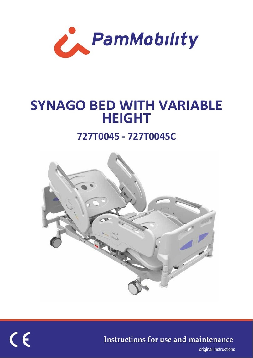
PamMobility PULSE 7M009001 NP Specification sheet

INSTRUCTIONS FOR USE AND MAINTENANCE
Translation of the original instructions
PULSE Specialist Stretchers
7M009001_NP - 7M009001_NPD - 7M009002_NP

REVISIONS TABLE
Revision Date Notes
0.0 15/11/2016 First edition
0.1 01/12/2020 CE marking pursuant to
Regulation (EU) 2017/745

ID05449 - Rev. 0.1 - 01/12/2020 3
CONTENTS
1. GENERAL PROVISIONS...................................................................5
1.1 Presentation of the manual................................................................................... 6
1.2 Customer Service ................................................................................................. 6
1.3 Conventions.......................................................................................................... 6
2. GENERAL WARNINGS......................................................................7
2.1 Manufacturer ........................................................................................................ 7
2.2 Intended use......................................................................................................... 7
2.3 Essential performance.......................................................................................... 7
2.4 Environmental limits of use................................................................................... 7
2.5 Expected lifespan ................................................................................................. 7
2.6 Identication ......................................................................................................... 8
2.7 Identicationofthecontrols.................................................................................. 8
3. SAFETY...............................................................................................9
3.1 General provisions................................................................................................ 9
4. GENERAL DESCRIPTION ..............................................................10
4.1 Stretcher Description .......................................................................................... 10
4.2 Technical characteristics..................................................................................... 11
4.3 Electrical data ..................................................................................................... 11
4.4 Battery ................................................................................................................ 12
4.5 Control console................................................................................................... 14
4.6 Control push-button panel .................................................................................. 15
5. INSTALLATION ................................................................................16
5.1 Transportation and delivery ................................................................................ 16
5.2 Lifting .................................................................................................................. 16
5.3 Storage ............................................................................................................... 16
5.4 Installation .......................................................................................................... 17
5.5 Checking the equipment..................................................................................... 17
5.6 Assembly ............................................................................................................ 17
5.7 Electrical connection........................................................................................... 17
5.8 Functional test .................................................................................................... 18
6. OPERATION AND USE....................................................................19
6.1 Warnings............................................................................................................. 19
6.2 Secure position................................................................................................... 19

ID05449 - Rev. 0.1 - 01/12/2020
4
6.3 Locking and unlocking the stretcher ................................................................... 19
6.4 Handling the stretcher ........................................................................................ 20
6.5 Raise and lower the stretcher............................................................................. 20
6.6 Raise and lower the backrest section................................................................. 21
6.7 Raise and lower the upper section of the legs (only on mod. 7M009002_NP)... 22
6.8 Raise and lower the lower section of the legs (only on mod. 7M009001_NPD -
7M009002_NP) .......................................................................................................... 23
6.9 Trendelenburg – Reverse Trendelenburg........................................................... 24
6.10 Longitudinal translation....................................................................................... 25
6.11 Handling the sides .............................................................................................. 26
7. SANITISATION .................................................................................27
7.1 Sanitising products ............................................................................................. 27
7.2 Sanitisation with halogen-containing products ................................................... 27
7.3 Sanitisation intervals........................................................................................... 27
7.4 Automatic sanitisation......................................................................................... 27
7.5 Manual sanitisation............................................................................................. 27
8. MAINTENANCE................................................................................28
8.1 Periodic check .................................................................................................... 28
8.2 Technical support................................................................................................ 28
8.3 Long term storage .............................................................................................. 28
8.4 Demolition and disposal ..................................................................................... 29
8.5 Sanitisation products .......................................................................................... 29
9. WARRANTY ......................................................................................29
10. ELECTRICAL SYSTEM WIRING DIAGRAM .................................30
11. ACCESSORIES ................................................................................31
11.1 Additional push bar code 2MK00545 and IV pole-holder bar with clamp code
4MK00073 .................................................................................................................. 31
11.2 4 hook drip pole code 7M009011........................................................................ 33
11.3 DIN bar monitor-holder system code 7M009044................................................ 35
11.4 Monitor/tablet-holder with variable height code 7M009017 ................................ 38
11.5 Roll-holder for Pulse code 7M009015 ................................................................ 40

ID05449 - Rev. 0.1 - 01/12/2020 5
EU Declaration of Conformity
The
manufacturer:
Company: Pam Mobility s.r.l.
Address: Via Verdi, 39 - 42043 Gattatico (RE) - Italy
Declares, under its own and exclusive responsibility, that the device(s)
Code Model ID BD/RDM BASIC UDI-DI
7M009001_NP Specialist 2-section electric stretcher 1521079/R 8055774207M009001_NPRC
7M009001_NPD Specialist 3-section electric stretcher 2058260/R 8055774207M009001_NPD6J
7M009002_NP Specialist 4-section electric stretcher 2058261/R 8055774207M009002_NPRK
Intended use: The device is intended to be used exclusively as a stretcher for the transportation,
diagnosis, treatment and monitoring of patients under the close supervision and
surveillance of medical personnel.
The device cannot be used for inpatient purposes
Environment of use: within healthcare and health facilities.
Thedevicecannotbeusedinapotentiallyexplosiveorammableatmosphere.
Personnel intended for use of the product: specialist operators and doctors.
Risk class: Class I
It complies with the following European Union legislative acts:
2017/745/EU
Regulation (EU) 2017/745 of the European Parliament and of the Council of 5 April 2017
on medical devices, amending Directive 2001/83/EC, Regulation (EC) no. 178/2002 and
Regulation (EC) no 1223/2009 and repealing Council Directives 90/385/EEC and 93/42/
EEC
2006/42/EC Directive 2006/42/EC of the European Parliament and of the Council of 17 May 2006 on
machinery and amending Directive 95/16/EC
2014/35/EU
Directive 2014/35/EU of the European Parliament and of the Council of 26 February
2014 on the harmonisation of the laws of member States relating to the making available
on the market of electrical equipment designed for use within certain voltage limits
2014/30/EU
Directive 2014/30/EU of the European Parliament and of the Council of 26 February
2014 on the harmonisation of the laws of member States relating to electromagnetic
compatibility
2011/65/EU
Directive 2011/65/EU of the European Parliament and of the Council of 8 June 2011
on the restriction of use of certain hazardous substances in electrical and electronic
equipment
It complies with the following common harmonised standards and/or specications:
CEI EN 60601-1:2007 Medical electrical equipment
Part 1: General requirements for fundamental safety and essential performance
The device is subject to the conformity assessment procedure provided for in article 52, section 7 of Regulation
2017/745/EU
Gattatico,
22/01/2021
Managing Director
Andrea Muzzini

ID05449 - Rev. 0.1 - 01/12/2020
6
1. GENERAL PROVISIONS
1.1 Presentation of the manual
This manual is intended to provide the user with all the necessary information so that, in addition
to suitable use of the device, they are able to manage it as autonomously and as safely as
possible.
Read carefully the warnings and instructions contained in this manual as they provide important
indications regarding SAFETY, USE AND MAINTENANCE.
Before carrying out any operation on the device, operators and qualied technicians must
carefully read the instructions contained in this publication.
In the event of any uncertainty about the correct interpretation of the instructions, please contact
ourocetoobtainthenecessaryclarications.
The descriptions and illustrations provided in this publication are non-binding.
Pam Mobility reserves the right to make any changes it deems appropriate for the purpose of
improvement, without undertaking to update this documentation.
The illustrations and images contained in this manual are intended only as examples and may
dierfrompracticalsituations.
This manual is an integral part of the device and must be kept with the utmost care by the
purchaser. It must be placed in the immediate vicinity of the device, inside a dedicated container
and, above all, protected from liquids and anything else that could compromise its readability.
The manual must accompany the device if it is transferred to a new user.
The contents of this manual are in accordance with Regulation 2017/745/EU of 05.04.17 (class
I), concerning medical devices.
It is forbidden for anyone to disclose, modify or use this manual for their own purposes.
Theoperatorandpatientsafetyandecientoperationdependoncompliancewithandexact
observance of the instructions described here.
1.2 Customer Service
Customer Service and product support are important aspects of the Pam Mobility s.r.l. company
structure.
Customer Service is available for further information on the use, maintenance and support of
this product.
1.3 Conventions
The following graphic symbols have been adopted in this manual:
ATTENTION! Placed before certain procedures. Failure to do so may result in
damage to the item.
WARNING! Placed before certain procedures. Failure to do so may cause damage
to the operator or patient and to the item.

ID05449 - Rev. 0.1 - 01/12/2020 7
2. GENERAL WARNINGS
2.1 Manufacturer
The item described in this manual is manufactured by:
2.2 Intended use
The device is intended to be used exclusively as a stretcher for the transportation, diagnosis,
treatment and monitoring of patients under the close supervision and surveillance of medical
personnel.
The device cannot be used for inpatient purposes
Environment of use: within healthcare and health facilities.
Thedevicecannotbeusedinapotentiallyexplosiveorammableatmosphere.
Personnel intended for use of the product: specialist operators and doctors.
2.3 Essential performance
The aspects of essential performance of the stretcher include:
▪Height adjustment: by means of a button control it is possible to electrically adjust the
height of the bed surface.
▪Backrest inclination adjustment: the stretcher is equipped with a manually operated
mechanism with millimetre adjustment which, once released, allows adjustment of the
inclination of the backrest section.
▪Trendelenburg/Reverse Trendelenburg: by means of a button control it is possible to
electrically adjust the inclination of the bed surface until the Trendelenburg/Reverse
Trendelenburg position is obtained.
▪Longitudinal translation: the stretcher is equipped with a manually operated mechanism
with millimetre adjustment which, once released, allows sliding of the bed surface in order to
maximise the examination area.
2.4 Environmental limits of use
WARNING! The stretcher cannot be used in a potentially explosive or ammable
atmosphere.
The environmental working conditions of the stretcher must respect these indications:
▪Temperature: 0°C ÷ +40°C
▪Humidity: 10% ÷ 70% (non-condensing).
The device must be placed in an absolutely dry environment.
Environmental conditions other than those indicated may cause serious damage to the stretcher.
Positioning of the stretcher in environments that do not correspond to what is indicated will
invalidate the warranty.
2.5 Expected lifespan
The stretcher has been designed and built to operate without risk to property and persons under
theordinaryconditionsofusedenedinthismanualfor10years.However,thisdurationcan
only be achieved by complying with the requirements set out in this manual and by contacting
Pam Mobility s.r.l. assistance whenever a malfunction occurs on the stretcher. After 10 years of
use it is advisable to replace the entire stretcher.
Pam Mobility s.r.l.
Via Verdi 39 – 42043 Gattatico (RE) - Italy
Tel. 0522 473859 - Fax 0522 1548244
Email: info@pammobility.com
http: www.pammobility.com

ID05449 - Rev. 0.1 - 01/12/2020
8
2.6 Identication
ATTENTION! It is forbidden to remove the label from the device for any reason.
Theitemisidentiablebytheplateonthebaseonwhichthefollowingdataareshown:
1. Company logo;
2. Name and address of the manufacturer;
3. CE marking;
4. Batch number;
5. Date and country of manufacture;
6. Medical device;
7. Item name
8. Item code;
9. Serial number;
10. Safe workload;
11. Maximum patient weight;
12. Uniquedeviceidentier(UDI);
13. Attention: be careful when using the medical device;
14. Read the user instructions;
15. Type B applied part;
16. Special waste;
17. Degree of IP protection;
18. Voltage and frequency of power supply absorbed;
19. Fuse;
20. Operation.
= Kg
Pam Mobility srl
Via Verdi, 39 - 42043 Gattatico (RE) Italy
Tel. +39 0522 473859
info@pammobility.com
<Vettore UDI>
<C.l.s.> <P max>
= Kg
xxx-xxxV ±10% - 50/60Hz
xxxxVA
X xTXAH XXXV (5x20)
USO MAX 2/PAUSA 20
IPXX
NOME ARTICOLO
<ID CODICE>
<Descrizione Arcolo>
<SERIAL NUMBER>
MD
UDI
IT
<Lot>
<Anno>
FAC-SIMILE
4
5
10
13
17
7
8
9
12
20
14 18 15 16 19
111 2 36
2.7 Identication of the controls
Thecontrolsanddevicesareidentiedbylabelsplacednearoronthedevicesthemselves.
MAXIMUM WEIGHT
PATIENT
SAFE WORK LOAD
=
Kg
PESO MASSIMO
PAZIENTE
CARICO DI LAVORO
SICURO
PERICOLO
SCHIACCIAMENTO
REGOLAZIONE SCHIENALE
REGOLAZIONE
TRENDELENBURG
BLOCCAGGIO
SBLOCCAGGIO
FRENI
BACKREST
ADJUSTMENT

ID05449 - Rev. 0.1 - 01/12/2020 9
3. SAFETY
3.1 General provisions
WARNING! Improper use and maintenance can cause damage to persons and
property.
WARNING! WARNING FOR BLOOD-BORNE DISEASES: To reduce the risk of
exposure during use of the stretcher, follow the maintenance instructions in
this manual, in addition to the instructions on personnel safety prepared by the
Emergency Medical Service Manager.
Operators must carefully read this manual, follow the instructions contained therein and
familiarise themselves with the correct procedures for use and maintenance of the stretcher.
Use and perform maintenance on the item only as prescribed in this manual and use only Pam
Mobility s.r.l. spare parts and assistance.
Do not use the stretcher for purposes other than those for which it was conceived and designed.
Always notify the patient before making any adjustments to the stretcher.
Always lock the stretcher with the brakes when it is not in transit.
Never leave the stretcher unattended when the patient is on it.
Keep this manual for reference and to support personnel training.
Transfer it together with the product in case of sale or transfer to new users.

ID05449 - Rev. 0.1 - 01/12/2020
10
1. Control console/push-button panel;
2. Battery;
3. Terminal for equipotential connection;
4. Brake pedal;
5. Column cover casing;
6. Lifting columns;
7. Fifth directional wheel control (optional);
8. Swivel castors;
9. Standard guide for attachment of
accessories;
10. Collapsible sides;
11. Mattress (accessory?);
12. Support surface;
13. Backrest;
14. Backrest release lever;
15. IV pole;
16. Mattress stopper;
17. Bed surface translation lever;
18. Foot side push handle;
19. Roll-up cable;
20. Side release lever;
21. Accessory support;
22. Head side push handle.
4. GENERAL DESCRIPTION
4.1 Stretcher Description
The PULSE Stretcher has been designed for use in healthcare facilities. For the purposes of
Regulation 2017/745/EU, it is to be understood as a non-therapeutic active device (class I).
4.1.1 Name of the main parts

ID05449 - Rev. 0.1 - 01/12/2020 11
4.2 Technical characteristics
PULSE STRETCHER 7M009001_NP 7M009001_NPD 7M009002_NP
Sections - 2 3 4
Surface dimensions mm 2050 x 740
Overall dimensions mm 2295 x 975
Minimum bed surface height mm 595
Maximum bed surface height mm 995
Trendelenburg Inclination / Reverse
Trendelenburg deg +13 / -13
Longitudinal surface translation mm / 480 480
Safe work load1kg 320
Patient weight kg 260
Standard wheel diameter mm 150
Mattress dimensions mm 2000 x 740
Maximum mattress thickness mm 100
Weight kg 112
1WORKLOADisdenedasthesumofthefollowing:patient(260Kg),mattress(10Kg)andaccessories(50kg).
4.3 Electrical data
PULSE STRETCHERS
Supply Voltage VAC 100-240
Network frequency Hz 50-60
Operating voltage VDC 24
Maximum power absorbed VA 200
Sound pressure level emitted under load dB <60
Electrical protection class - I
Applied part - Type B
Degree of protection against dust and liquids - IP54
Operation /pause min/
hour
10% or 2 minutes of operation
followed by 18 minutes of pause

ID05449 - Rev. 0.1 - 01/12/2020
12
4.4 Battery
The stretcher is equipped with an acid-free buer battery that allows height and inclination
adjustments even in the absence of a connection to the mains.
The capacity of the battery guarantees an autonomy of approximately 20 complete lifting/
lowering cycles.
The residual charge level is indicated by the indicator light (E).
The battery can be activated and deactivated via two buttons, ON and OFF, located on the
battery housing. The LED located next to the buttons indicates the status of the battery: if
GREENGREEN the battery is charged, if ORANGEORANGE the battery is low.
NOTE: if the battery is low, it emits an audible alarm each time the sections are moved.
To charge the battery, simply connect the power cable to the mains or use the battery charger
(accessory code 7M009042).
N.B.: leaving the power cable plugged in for long periods will in no way damage the battery. The
control unit is equipped with software that manages the charge optimally.
Even in the case of a completely depleted battery, it is still possible to use the stretcher. In this
case it will not be possible to adjust the height of the bed surface.
4.4.1 Fitting the battery
Totthebatteryproceedasfollows:
▪assume a position at the head side of the stretcher and open the velcro strap;
▪insert the battery into the battery housing (Fig. 1);
▪do not release the battery before having heard the locking "click" and having wrapped the
Velcro safety strap around the battery body;
▪connect the power plug of the stretcher to the power outlet: the battery will start charging and
the LED of the battery and of the console (E)willstartashingORANGE;whenthebattery
has completed charging, the LED will turn GREEN.
Fig. 1 Fig. 2
Velcro strap
Battery housing
Green led on
Press ON

ID05449 - Rev. 0.1 - 01/12/2020 13
4.4.2 To disassemble/replace the battery with accessory code 7M009042 Additional
battery complete with desk / wall battery charger
WARNING! Pressing the release lever, the battery immediately disengages from
the support so be sure to be holding it properly.
To disassemble the battery proceed as follows:
▪with one hand hold the battery and with the other open the velcro strap;
▪press the battery release lever (image below) being sure to support it properly (Fig. 2);
▪connect the battery charger to the power socket and connect the battery; an ORANGE LED
on the battery charger transformer will light up to indicate that the battery is charging; the
charging time can take from 4 to 12 hours depending on the remaining charge;
▪when the battery is fully charged, the LED will light up GREEN;
▪disconnect the battery from the battery charger and insert it back into the stretcher;
▪turn on the battery by pressing the ON button on the battery housing on the stretcher: a
GREEN LED will light up indicating that the battery is on and charging.
Wall/wall battery charger
Battery release
lever

ID05449 - Rev. 0.1 - 01/12/2020
14
4.5 Control console
ATTENTION! Before carrying out any movement, consult the paragraph on the
manoeuvre to be performed.
The stretcher is equipped with a 5-button 2-function control console.
The functions of the console buttons are as follows:
A. Raise the bed surface;
B. Lower the bed surface;
C. Reverse-trendelenburg adjustment;
D. Trendelenburg adjustment;
E. Indicator light: indicates the residual charge level of the battery;
F. Device on button: the stretcher is in fact equipped with an auto switch o system that
activates after 1 minute of inactivity. This is to avoid unintentional activation and to preserve
battery life when not powered by the mains cable.
4.5.1 Turning on the device
To allow the device to turn on, it is necessary to rst connect and turn on the battery (see
section 4.4 Battery).
Once the battery has been turned on (ON) press the button Fand keep it pressed until the
lights Eturn on (The activation time is approximately two seconds).
The battery charge status is displayed when one of the movement keys A, B, C or D is pressed.
When the stretcher is powered by the network cable, the console always remains active and to
make any movement it is not necessary to switch on using the button F.
As soon as the stretcher is connected to the network, the display E automatically switches to
"charging" mode (see para. 4.4).

ID05449 - Rev. 0.1 - 01/12/2020 15
4.6 Control push-button panel
The stretcher supports a free push-button panel with 4 keys and 2 functions.
ATTENTION! Before carrying out any movement, consult the paragraph on the
manoeuvre to be performed.
A
C
B
D
The movements that can be made using the push-button
panel are as follows:
A. Raise the bed surface;
B. Lower the bed surface;
C. Reverse-trendelenburg adjustment:
D. Trendelenburg adjustment.
SYSTEM RESET: press buttons Aand Cat the same
time; the stretcher reaches its maximum height, then
emittinga"beep".Waitforthethreeashesofthegreen
LED Z: the reset has been successful.
Z

ID05449 - Rev. 0.1 - 01/12/2020
16
5. INSTALLATION
Thehandlingactivitiesdescribedinthischaptermustbecarriedoutexclusivelybyqualied
personnel specially trained to perform in complete safety the operations of loading, unloading
andhandling of packs by means of lifting tools suchas cranes or forklift trucks. Local sta
should be aware of the accident-prevention rules.
5.1 Transportation and delivery
Transportation can be carried out by the following means of communication: road, rail, sea, air.
The weight of the item can be ascertained from the technical characteristics and packaging.
Movement of the individual item must be performed using means suitable for handling such as
the self-propelled forklift truck or the manual forklift truck.
The precautions for safety at work remain valid.
Thedeviceisdeliveredassembledwrappedinashockproofbubblewraplm.
ATTENTION! Upon receipt of the device, check with the carrier that the material is
intact, that it has not been damaged during transportation or has not been opened
intentionally to remove parts inside. Check that the supply corresponds to the
specications of the order and verify with the shipping documents that the delivery
is complete.
If the packaging is damaged externally, open it in the presence of the carrier and check that the
stretcher has not been damaged.
Note any damage on the shipping documents and immediately inform the Company Pam
Mobility s.r.l.
If the packaging does not show anomalies, check the stretcher externally within 24 hours of
delivery.
In case of visible damage due to transportation, immediately inform the carrier and the insurer,
as well as the Company Pam Mobility s.r.l.
5.2 Lifting
WARNING! Lifting and handling operations must be carried out by specialist
personnel trained in these types of manoeuvres.
ATTENTION! When lifting, slowly tension the straps and check that no components
are involved that are not suitable to support the weight of the unit
In order to ensure safe handling of the stretcher, strictly follow these instructions:
▪make sure that the lifting equipment is suitable for the weight of the stretcher;
▪useonlyatliftingstraps;
▪place the lifting straps near the trolley frame and not near the mesh frame;
▪if forklift trucks are being used, place the stretcher on a suitable platform, locking the four
wheels;
▪liftthestretcherothegroundaslittleaspossible.
ATTENTION! During the manoeuvre, check that no part of the stretcher remains
compressed against the lifting equipment.
5.3 Storage
In case of prolonged storage, leave the stretcher protected from rain and wind and in a dry
place.
Protect especially well all parts that are very sensitive to humidity and low temperatures.
The stretcher can be stored in dry rooms with a temperature of between -10°C and +50°C; and
relative humidity 20% ÷ 90% without condensation.

ID05449 - Rev. 0.1 - 01/12/2020 17
5.4 Installation
InstallationtakesplaceunderthedirectionandresponsibilityofaqualiedtechnicianofPam
Mobility s.r.l.
ATTENTION: it is absolutely forbidden to assemble and install the stretcher without
the support of a qualied technician of Pam Mobility s.r.l. Similarly, it is absolutely
forbidden to disassemble the stretcher for subsequent reinstallation without the
support of a qualied technician of Pam Mobility s.r.l.
Checkthattheinstallationsurfaceissucientconsideringtheadditionalspacenecessaryfor
assembly.
Makesurethatthespaceleftnexttothestretcherissucientforapersontopassby.
Makesurethatthespecicoorcapacityissucienttosupporttheweightofthestretcherwith
the safe work load applied.
5.4.1 Preparing the installation area
Theplaceofinstallationmusthavearigid,horizontal,atoor.
5.5 Checking the equipment
The packaging contains:
▪PULSE stretcher (ordered model);
▪additional accessories ordered;
▪the user instruction manual.
5.6 Assembly
ATTENTION! The assembly area must be clean and clear; it must be at least 4x3 m
to allow assembly operations.
The place of assembly must have the following characteristics:
▪at,non-yieldingoor;
▪400 LUX lighting.
5.7 Electrical connection
WARNING! The electric stretcher cannot be used in a potentially explosive or
ammable atmosphere (such as a hyperbaric chamber).
ATTENTION! Danger of electric shock. The cables must be positioned in such a
way that they cannot be crushed, trapped, pulled taut, walked on, bent, become
wet or obstructed with respect to the moving parts.
WARNING! The power cable must not cause obstruction to the operator.
WARNING! Check that the mains voltage and frequency correspond to that
indicated on the identication plate.
▪Prepare a SCHUKO type socket;
▪connect the plug to the power supply;
▪the stretcher must be charged for at least 12 hours before use.

ID05449 - Rev. 0.1 - 01/12/2020
18
5.8 Functional test
ATTENTION! The following check must be repeated periodically to verify the
eciency of the product.
Before putting the item into use:
▪perform the "periodic check" provided for in the maintenance chapter;
▪if the check is successful, the item is ready to be put into regular service, otherwise contact
Pam Mobility Customer Service immediately.

ID05449 - Rev. 0.1 - 01/12/2020 19
6. OPERATION AND USE
6.1 Warnings
The electric stretcher cannot be used in a potentially explosive or ammable
atmosphere (such as a hyperbaric chamber).
Before moving the stretcher, make sure that the power cable is disconnected and
rewound.
Sanitise the stretcher as described in the SANITISATION chapter.
Notify the patient whenever stretcher adjustments are to be made.
Always lift the safety rails of the stretcher when a patient is on it. Always lock the
stretcher when it is not in transit by applying the brakes.
Do not use the device for purposes other than those for which it was intended and
for which it was designed.
6.2 Secure position
The stretcher is in a safe position when the mesh surface is in the horizontal position in the
lowest position with the sides raised and the brake engaged.
6.3 Locking and unlocking the stretcher
The stretcher is equipped with four swivel braking wheels and one with directional function (5th
wheel).
If the pedal is in the horizontal GREEN position, the wheels are free.
Pressing the pedal to the RED position inserts the brake and locks the wheels.
The directional lock (5th wheel) is activated by raising the pedal to the BLUEposition.
BLUE GREEN RED

ID05449 - Rev. 0.1 - 01/12/2020
20
6.4 Handling the stretcher
WARNING! Always notify the patient before moving the stretcher.
WARNING! Movement must only take place on rigid at surfaces and with the rails
raised. Always lock the stretcher at the end of handling.
WARNING! Make sure before moving the stretcher that the power cable is
disconnected from the mains socket and that it is rewound so that it does not
obstruct movement.
To move the stretcher proceed as follows:
▪release the brakes;
▪make sure that the sides are raised;
▪push or pull the stretcher by gripping it by the push handles;
▪at the end of the journey, lock the stretcher.
6.5 Raise and lower the stretcher
WARNING! Always notify the patient before adjusting the height of the stretcher.
Height adjustment of the stretcher is obtained by means of two electric actuators controlled via
the push-button panel and the control console.
To adjust the height of the stretcher proceed as follows:
▪press the power button Fand keep it pressed until the lights come on;
▪press button Ato raise the stretcher;
▪press button Bto lower the stretcher.
A B
This manual suits for next models
5
Table of contents
Other PamMobility Medical Equipment manuals
Popular Medical Equipment manuals by other brands

Keeler
Keeler Cryomatic 2509-P-1000-JPN Service manual

Freedom Innovations
Freedom Innovations Plie 2.0 user guide

Tidal
Tidal InSee Instructions for use

Otto Bock
Otto Bock 1C20 ProSymes Instructions for use

Sedatelec
Sedatelec Premio 30 laser duo user manual

FujiFilm
FujiFilm SonoSite SII User guide supplement