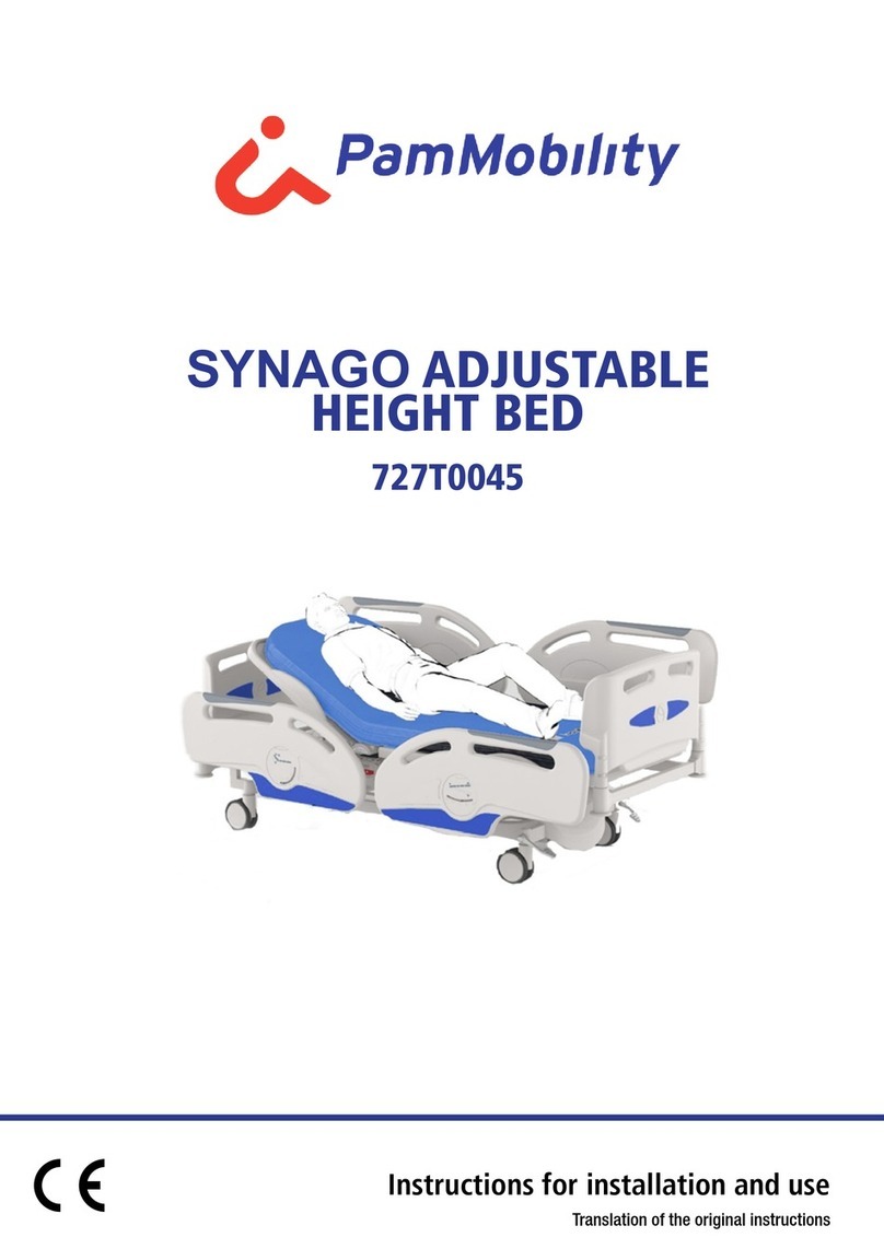
PamMobility SYNAGO Specification sheet

SYNAGO BED WITH VARIABLE
HEIGHT
727T0045 - 727T0045C

REVISION TABLE
Revision
Data
Note
0.0
15/11/2016
First edition
0.1
02/07/2018
Update general description,
technical data, sides, lower section
of the legs
02/07/2018
Update general description, technical
data, sides, lower section of the legs
0.2
23/10/2019
Insertion variant 727T0045S
0.3
14/04/2021
CE marking according to Regulation
(EU) 2017/745
1.1
22/03/2023
Insertion variant 727T0045C
1.2
19/04/2023
Data update, label

3
ID08435 - Rev. 1.2 - 19/04/2023
Summary
Summary ................................................................................3
1.
GENERAL PROVISIONS
.......................................................
7
1.1 Presentation of the handbook
.................................................................
7
1.2 Services with reduced costs
..................................................................
7
1.3
Conventions....................................................................................... 7
2.
GENERAL POWERS
.............................................................
8
2.1
Constructor ........................................................................................ 8
2.2 Intended
use
........................................................................................
8
2.3
Essential performance of the product
.................................................... 8
2.4
Environmental limitation of use
............................................................... 8
2.5 Expected life
........................................................................................
8
2.6
Identifying........................................................................................... 9
2.7 Identification of commands
...................................................................
9
3.
SAFETY .........................................................................10
3.1 Safety standards
.................................................................................
10
3.2
General provisions
............................................................................ 10
4.
GENERAL DESCRIPTION
....................................................
11
4.1
Description of the project ............................................................... 11
4.2 Technical characteristics
......................................................................
14
5.
PUSH BUTTON ..............................................................15
5.1 Remote control
...................................................................................
15
5.2
Control Box ( optional cod.82700018)
................................................... 16
5.3 Bilateral pedal board (optional cod.
82700077)
.........................................
16
5.4 Control
panel(
optional
od
.82700066)
....................................................
17
5.5
Control panels for kit with 4 folding sides
(optional Cod
.
82700087)
......................................................................................................... 18
6.
INSTALLATION..............................................................21
6.1
Transport
..........................................................................................
21
6.2
Lifting ............................................................................................... 21
6.3
Storage ............................................................................................ 22
6.4
Installation........................................................................................ 22

4
ID08435 - Rev. 1.2 - 19/04/2023
6.5 Adequacy check
................................................................................
22
6.6
Assembly ......................................................................................... 23
6.7 Mounting Side Panels( cod . 7300007A)
.................................................
23
6.8 Electrical connection
...........................................................................
24
6.9
Test
funzionale
...................................................................................
24
7.
FUNCTIONING
..................................................................
25
7.1
Warnings.......................................................................................... 25
7.2 Safe location
......................................................................................
25
7.3 Emergency positions
..........................................................................
25
7.4
Move
................................................................................................ 28
7.5
Block
.............................................................................................. 28
7.6
Alarm on wheels for unbraked bed (accessory 82700043)
.................... 29
7.7
Courtesy light device (accessory 82700086 or included in side panel kit
82700087)
.................................................................................... 29
7.8
Raise and lower the
........................................................................... 30
7.9
Raise and lower the backrest section ......................................... 31
7.9
Raise and lower the upper leg section
.............................................. 33
7.10
Simultaneously raise and lower the back section and the upper leg section
(
Autocontour )
................................................................................. 35
7.11 Trendelenburg e reverse trendelenburg
.................................................
37
7.12 Comfort
position (
chair)
........................................................................
39
7.13
RCP
...............................................................................................
40
7.14 Trendelenburg emergency
...................................................................
41
7.15
CPR backrest release emergency device
............................................
42
7.16 Location of security at night
................................................................
43
7.17
Raise and lower the lower section of the legs
...................................... 44
7.19 Integrated bed extension ( optional code 82700038 )
.................................
46
7.20
4-sector side rail movement ( optional code 7300009A )
.................................
47
7.21
Compass sides movement ( optional cod . 7300007A )
..................................
48
7.22 Disassemble the bumper (cod . 7300007A)
.............................................
49
7.23 Linkingpotential solutions
.....................................................................
50
7.24
Floorboard
......................................................................................... 50
8.
ACCESSORIES..............................................................51
9.
SANITATION..................................................................52
9.1
Sanitizing products .......................................................................... 52

5
ID08435 - Rev. 1.2 - 19/04/2023
9.2
Sanitization with products containing halogens ............................ 52
9.3
Sanification with food additives
.......................................................... 52
9.4
Intervallinification
............................................................................... 53
9.5 Automatic sanitization
.........................................................................
53
9.6 Manual sanitization
..............................................................................
53
10.
MAINTENANCE .............................................................54
10.1 Periodic check
...................................................................................
54
10.2 Technical assistance
...........................................................................
54
10.3
Provision .......................................................................................... 54
10.4 Demolition
........................................................................................
55
10.5
Battery.............................................................................................. 55
10.6 Resolution of problems
.......................................................................
56
11.
GUARANTEE .................................................................56
12.
ELECTRICAL SYSTEM DIAGRAM ................................57

6
ID08435 - Rev. 1.2 - 19/04/2023

7
ID08435 - Rev. 1.2 - 19/04/2023
1.
GENERAL PROVISIONS
1.1 Presentation of the manual
This manual is intended to provide the user with all the necessary information so that,
in addition to proper use of the device, it is able to manage the same in the most
autonomous and safe way possible.
It includes information regarding the technical aspect, operation, device
downtime, maintenance, spare parts and safety.
Please
read the warnings and the instructions contained in the manual as they
provide
important information regarding the SAFETY OF USE AND MAINTENANCE.
Before carrying out any operation on the device, qualified operators and technicians
should read carefully the instructions contained in this publication.
In case of doubts about the correct interpretation of the instructions, contact our office
to obtain the necessary clarification.
The descriptions and illustrations given in this publication are intended as non-binding. Pam
Mobility reserves the right to make changes that it deems convenient for improvement
purposes, without committing to updating this documentation.
The illustrations and images in this manual are intended only as examples and may
differ from practical situations.
The content of this Manual complies with Regulation (EU) 2017/745 of the European
Parliament and of the Council of 5 April 2017 on medical devices, amending Directive
2001/83/EC, Regulation (EC) No 178/2002 and Regulation (EC) No. 178/2002 n.
1223/2009 and repealing Council Directives 90/385/EEC and 93/42/EEC.
Any person may not disclose, modify or use this manual for his or her own purposes. The
safety of the operator and the patient and the smooth operation of the patient depend on
compliance with the instructions described here.
1.2 Customer service
Customer Service and product support are important aspects of the Pam Mobility
SRL corporate structure.
Customer Service is available for further information on the use, maintenance and
service of this product.
1.3
Conventions
The following symbols have been adopted in this manual:
ATTENTION! It is placed before certain procedures. Failure to do so may cause damage to
the article.
WARNING! It is placed before certain procedures. Failure to do so may cause harm to the
operator, the patient and the article.

8
ID08435 - Rev. 1.2 - 19/04/2023
2.
GENERAL ASSETS
2.1
Constructor
The article described in this manual is produced by:
Pam Mobility s.r.l.
Via Verdi 39 - 42043 Gattatico (RE) -
Italy Tel 0522 473859 - Fax 0522
1548244
E-mail:
info@pammobility.comhttp:
www.pammobility.com
2.2 Intended use
▪
Device type: electric bed.
▪
The device is intended for use in the diagnosis, treatment and monitoring of
an adult patient* under the strict supervision of medical personnel.
▪
Use environment: hospitals and medical clinics in application environments 2 or 3.
The installation room must be equipped with electrical installation in accordance
with current standards.
▪
Personnel for use of the product: specialized operators and medical personnel.
▪
Supervision and responsibility: the bed should be used under the supervision of a
doctor.
▪
Warning: The bed cannot be used in a potentially explosive or flammable
atmosphere.
▪
Limits of use:the bed can be used only as described in this manual.
* Adult means a person weighing 40 kg or more, of a height of 146 cm or more and having a body mass
index (BMI) of 17 or more.
2.3
Essential performance of the bed
The essential benefits of the medical bed are:
▪
Trendelenburg location: the Trendelenburg location can be reached in any
condition via a push-button in less than 30 seconds;
▪
horizontal network plane: it is possible to bring the network plane in any condition
horizontally through a push-button in a time less than 30 s;
▪
horizontal backrest: it is possible to bring the backrest section in any condition in
horizontal position thanks to the mechanical lever CPR in less than 30 s.
2.4 Environmental limits of use
WARNING! The bed cannot be used in a potentially explosive or flammable atmosphere.
The working environment of the bed shall be as follows:
▪
Temperature: 0
▪
Humidity: 10% 70% (not condensed).
The device must be placed in absolutely dry environment.
Environmental conditions other than those indicated may cause serious damage to the
bed. The placement of the bed in rooms not corresponding to the above makes the
warranty void.
2.5 Expected life
The bed has been designed and constructed to operate without risk to property
and persons under the normal conditions of use defined in this manual for 10
years. However, this duration can only be achieved by complying with the

9
ID08435 - Rev. 1.2 - 19/04/2023
requirements of this manual and contacting the assistance of Pam Mobility s.r.l.
whenever a bed failure occurs. After 10 years of use it is recommended to
replacethe interoletto.

10
ID08435 - Rev. 1.2 - 19/04/2023
2.6
Identifying
ATTENTION! It is forbidden to remove the label from the device for any reason.
The article is identifiable by the plate on the base in which the following data are shown:
A.
Company logo;
B.
Device description;
C.
Article code;
D.
Registration number of the device to the Ministry
E.
Safe working load;
F.
Date of production;
G.
Manufacturing data
H.
Warning: Read the installation and operating instructions.
I.
Electrical data;
L.
Vector UDI ( not present)
M.
Basic UDI-DI number;
N.
Serial number
O.
CE marking
P.
Name and manufacturer’s address
Q.
Applied part type B
2.7 Identification of controls
Controls and devices are identified by labels placed nearby or on the devices
themselves.
= Kg
HEAVYWEIGHT LOAD OF
Patient SAFE WORK
PHYSICAL
description
MATTRESS LABEL
LOWERING
QUICK EMERGENCY
BACKREST - CPR
CLAMP FOR DANGER
CONNECTION
EQUIPOTENTIAL
CRUSHING
BRAKE LABEL

11
ID08435 - Rev. 1.2 - 19/04/2023
3.
SAFETY
3.1 Safety rules
3.1.1
Definitions
The following terms shall be used in this Safety Manual:
Operator:
the person in charge of installing, operating, regular
performing maintenance, cleaning, repairing, and
transporting the device.
Technic Pam mobility:
qualified technician made available by Pam Mobility
s.r.l. or its agent to carry out operations of a complex nature,
installation and installation.
Safety components:
specially designed component by the manufacturer
and placed on the market separately from the device
in order to carry out the safety functions; it can
therefore be defined as a safety component when the
failure of the component itself affects the safety of the
exposed persons.
3.2 General provisions
WARNING! Improper use and maintenance can cause damage to people and property.
WARNING! NOTICE FOR BLOOD BORNE DISEASES: To reduce the risk of exposure during use
of the bed, follow the maintenance instructions in this manual, in addition to the safety
requirements for personnel established by the Head of the Emergency Medical Service.
Operators should carefully read this manual, follow the instructions contained in it and
familiarize themselves with the correct procedures of use and maintenance of the bed.
Use and carry out the maintenance of the article only as prescribed in this manual and
use only spare parts and assistance Pam Mobility s.r.l. Do not use Illetto for purposes
other than those for which it was designed.
Always advise the patient before making any adjustment of the bed. During
the stop, always lock the bed through the brakes.
Never leave the bed unattended when the patient is on it.
Keep this manual for consultation and to support staff training.
Transfer it together with the product in case of sale or transition to new users.
WARNING!
Report any serious incident that has occurred in relation to the device to the
manufacturer and the competent authority of the Member State where the user and/or
patient is established.

12
ID08435 - Rev. 1.2 - 19/04/2023
GENERAL DESCRIPTION
3.3 Description of the bed
Bed variable height with Trendelenburg 3 joints 4 sections, electrically adjustable, top in
technopolymer, shoulder side head independent.
The electric bed has been designed for use in specialist or semi-intensive care
units. For the purposes of the reference Directive the bed is to be understood as
an active non-therapeutic device (class I).

13
ID08435 - Rev. 1.2 - 19/04/2023
3.3.1 Title of main parts
1.
Keypad;
2. Control Box (optional cod. 82700018);
3. Bilateral pedals (optional cod. 82700077);
4. Control panel
5.
Base;
6.
Telaio rete;
7.
Headboard;
8.
Footboard;
9. Back section;
10. Basin section;
11. Upper section of the legs;
12. Lower section of the legs;
13.
Brake;
14.
Wheel;
15. Tailgate release handle;
16. Quick release lever back section;
17.
Bumper.


13
ID08435 - Rev. 1.2 - 19/04/2023
1.
Push-button
Push-button for patient and/or operator use with maintained action with possibility of
deactivable controls.
2. Control Box - Control inhibitor (optional cod. 82700018);
The function inhibitor panel is used when the patient’s position needs to be carefully
controlled by the medical staff. The panel is fixed to the bed frame out of the patient’s
reach and is used to block the functions of the free push-button.
3. Bilateral pedals (optional cod. 82700077)
Bilateral pedals for the height adjustment of the mesh. Placed on both sides of the bed
to
facilitate different positions
, and
intervene on the hands
-
free patient. Equipped
with safety protection to prevent involuntary operation.
4. Control panel (optional cod. 82700066);
Control panel for operator use with the possibility of inhibiting the controls of each
single bed movement. All functions can be activated via the buttons of consent to the
action maintained movement. There are also emergency hotkeys and comfort
positions.
5.
Base
Perimeter tubular structure in welded and epoxy painted steel, covered by an ABS
casing.
6. Frame net
Longitudinal metal structure on which the different sections rest.
7-8. Headboard and footboard
Headboard and footboard are the end part of the bed. They are shaped to allow
an easy grip in the movement of the bed and a pleasant aesthetic appearance.
They are available in various configurations.
9. Back section
Part of the support that supports the patient’s head and back.
10. Basin section
Central part of the shelf supporting the basin. It’s not a big deal.
11. Upper section of the legs
Mesh part that allows the lifting of the upper section of the legs.
12. Lower section of the legs
Mesh part that allows the lifting of the lower section of the legs by means of an
electric actuator or 6-position "Rastomat" snap mechanism.
13.
Brake
Pedal that allows you to lock or unlock the wheels and set the steering lock.
14.
Wheels
Connected to the base, they allow the movement of the bed.
15. Tailgate release handle
In case there are technopolymer half banks, it allows the lowering and the raising of
the same.
16. Quick release lever back section (CPR)
Lever that allows the quick release of the backrest section in case of emergency.
17.Bumpers (optional)
Wheels in plastic material that absorb any impact when moving the bed.

14
ID08435 - Rev. 1.2 - 19/04/2023
3.4 Technical characteristics
3.4.1
Dimensional data
ELECTRIC VARIABLE HEIGHT BED
727T0045 –
727T0045C
Sections -
4
Floor size
mm
2000 x 880
Height mm
380 ÷ 780
Encumbrance
mm
2260 x 1010 (960)
Back section
mm 700
Fixed section
mm 108
Upper section of the legs (pelvis)
mm 310
Lower leg section (footboard)
mm 730
Backrest adjustment
deg 0 ÷ 71
Back section translation - basin
mm 103 - 53
Upper leg section adjustment
deg 0 ÷ 30
Trendelenburg
deg 0 ÷ -15°
Reverse trendelenburg
deg 0 ÷ 15°
Bottom section of the frame
deg 0 ÷ 30
Safe workload
kg 270
Patient weight
kg 230
Standard wheel diameter
mm 150
Suggested dimensions mattress
mm
2000 x 850 x 180
h
Weight kg 130
3.4.2 Electrical data
ELECTRIC VARIABLE HEIGHT BED
727T0045 –
727T0045C
Supply voltage
V
100-240V-
50Hz
Network frequency
Hz
50
Operating voltage
Vcc 24
Max current absorbed To
1.5
Sound power level emitted under load
dB <60
Class of electrical protection
-
I
Applied part
-
Type B
Degree of electrical protection
-
IP66
Intermittent operation
min/ho
ur
10% or 2 minutes of operation
followed by 18 minutes of pause
Battery capacity
Ah 1,2
Battery charging time
h
10-12
Reference standards
CEIUNI EN 60601-2-52

15
ID08435 - Rev. 1.2 - 19/04/2023
4.
PUSH BUTTON
4.1 Free button panel
The bed supports a free push-button with 12 buttons and 6 functions.
ATTENTION! Before performing any handling, please refer to the section on the
manoeuvre to be carried out.
The movements that can be made by means of a push-button are as follows:
-
Raise the back;
To
-
Lower the backrest;
B
-
Raise the upper section of the
shankseC;
-
Lower the upper leg section;
D
-
Raise the lower section of the legs;
E
-
Lower lower leg section;
F
- Simultaneous raising of the back section and the upper section of the legs
G
-
Simultaneous lowering of the back section and the upper section of the legs
H
- Raise the bed;
I
-
Lower the bed;
L
-
Reverse trendelenburg;
M
-
Trendelenburg; N
- Led lighting on power on;
-
Key for locking and unlocking the Trendelenburg.
Or
4.1.1
UNFORESEEN

16
ID08435 - Rev. 1.2 - 19/04/2023
4.2 Inhibitor controls
The electric beds can support a Control Box inhibition console, which allows
operators to inhibit the functions of the free control panel.
Inhibition commands
To disable console commands, proceed as follows:
Press Tastoe A in
with the
padlock symbol closed and holding down the A key
also press the movement key that you want to inhibitree for example:
to exclude the movement of the backrest you will have to press the button A+
the
button
Dil green led on the edge button turns off
Inhibition commands
To unlock commands from console proceed as follows
Press the A button
in
with the lock symbol closed and holding the Open button
also
the movement key you want to unlock for example:
to exclude the movement of the backrest you will have to press the button A+
the
button
Dil green led on the edge button is lit
4.3 Bilateral pedals (optional cod. 82700077)
The electric beds can support a bilateral pedal board, which allows operators to raise
and lower the bed.
ATTENTION! Before performing any handling, please refer to the section on the
manoeuvre to be carried out.
The two-sided pedal movements are as follows:
- Raise the bed;
-
Put the bed down.

17
ID08435 - Rev. 1.2 - 19/04/2023
4.4 Control panel
The beds can have a control system that allows the operator to control, activate and inhibit
the functions of the free control panel.
There are also emergency hotkeys for CPR, comfort position, Trendelenburg. and patient
descent position
ATTENTION! Make sure the magnetic key
P is
inserted. Before performing any handling,
please refer to the section on the manoeuvre to be carried out.
Description:
-
Lock inhibition/ unlocking movements
A
-
Control of movement
B
-
Control of movement C descent
-
movement of the upper section of the backrest
D
-
movement of the upper leg section;
And
-
movement of the lower leg section ( if present )
F
-
up/down movement of bed
G
-
Handling of Trendelenburg/ controtrendelenburg;
H
-
simultaneous movement of the back and upper section of the legs;
I
-
Button for comfort position (armchair);
L
-
CPR button total reset;
N
-
Button for emergency Trendelenburg position M
-
Magnetic control console inhibition key.
P
-
Indicator led battery status/ presence network 230V

18
ID08435 - Rev. 1.2 - 19/04/2023
4.5
Control panels for kit 4 foldable sides ( NOT PROVIDED )
UNFORESEEN
4.5.1 Inhibition of commands from the control panel
UNFORESEEN
This manual suits for next models
3
Table of contents
Other PamMobility Medical Equipment manuals
Popular Medical Equipment manuals by other brands

GlideScope
GlideScope Titanium Operation & maintenance manual

Livassured
Livassured NightWatch Livanova Technical description

Kinova
Kinova JACO user guide

iCarsoft
iCarsoft MB II user manual

Welch Allyn
Welch Allyn Connex Vital Signs Monitor 6000 Series Service manual

GreatCall
GreatCall Lively Mobile+ user guide