14
SPECIFICATIONS
Model
DP-10 1 2 3 -4-5-6
1: 1: Low-pressure type, 2: High-pressure type
2: None: For outside of Japan, Z: For inside of Japan
3: None: Standard type, A: High-function type
4:
None: R
1
/
8
+
M5 female screw, E: G
1
/
8
+
M5 female screw, M: M5 female screw
N: NPT
1
/
8
+
M5 female screw
5: None: NPN output type, P: PNP output type
6: None: Cable with connector enclosed, J: No cable with connector
Type
Item
Standard type High-function type
Low-pressure type High-pressure type Low-pressure type High-pressure type
Pressure type Gauge pressure
Rated pressure range -100 to +100kPa -0.1 to +1.0MPa -100 to +100kPa -0.1 to +1.0MPa
Set pressure range -100 to +100kPa -0.1 to +1.0MPa -100 to +100kPa -0.1 to +1.0MPa
Withstand pressure 500kPa 1.5MPa 500kPa 1.5MPa
Non-corrosive gas
Supply voltage 12 to 24V DC ±10%
Power consumption
Normal operation: 840mW or less (current consumption 35mA or less at 24V supply voltage)
ECO mode (STD): 600mW or less (current consumption 25mA or less at 24V supply voltage)
ECO mode (FULL): 480mW or less (current consumption 20mA or less at 24V supply voltage)
Comparative output
<NPN output type>
NPN open-collector transistor
Maximum sink current: 100mA
Applied voltage: 30V DC or less
(between comparative output and 0V)
Residual voltage: 2V or less
(at 100mA sink current )
<PNP output type>
PNP open-collector transistor
Maximum source current: 100mA
Applied voltage: 30V DC or less
(between comparative output and +V)
Residual voltage: 2V or less
(at 100mA source current )
Output operation Selectable either N.O. or N.C., with key operation
Hysteresis Min. 1 digit (variable) (however, 2 digits when using psi units)
Repeatability ±0.1% F.S.
± within 2 digits
±0.2% F.S.
± within 2 digits
±0.1% F.S.
± within 2 digits
±0.2% F.S.
± within 2 digits
Response time 2.5ms, 5ms, 10ms, 25ms, 50ms, 100ms, 250ms, 500ms, 1.000ms or 5,000ms
selectable with key operations
Analogue voltage output
<High-function, low-pressure type>
Output voltage: 1 to 5V
Zero point: Within 3V ± 5% F.S.
Span: Within 4V ± 5% F.S.
Linearity: Within ± 1% F.S.
<High-function, high-pressure type>
Output voltage: 0.6 to 5V
Zero point: Within 1V ± 5% F.S.
Span: Within 4.4V ± 5% F.S.
Linearity: Within ± 1% F.S.
External input
<High-function NPN output type>
ON voltage: 0.4V DC or less
OFF voltage: 5 to 30V DC or open
Input time: 1ms or more
<High-function PNP output type>
ON voltage: 5V to +V DC
OFF voltage: 0.6V DC or less or open
Input time: 1ms or more
Ambient temperature -10 to +50°C (No dew condensation or icing allowed), Storage: -10 to +60°C
Ambient humidity 35 to 85% RH, Storage: 35 to 85% RH
Temperature characteristics Within ±0.5% F.S.
(at +20°C reference)
Within ±1% F.S.
(at +20°C reference)
Within ±0.5% F.S.
(at +20°C reference)
Within ±1% F.S.
(at +20°C reference)
Material
Pressure port: Stainless steel (SUS 303)
Mounting screw section: Brass (nickel-plated), O-ring: H-NBR, Key part: Silicon rubber
Weight
Approx. 40g (DP-100-E type: Approx. 45g, DP-100-M type: Approx. 30g) (Main body only)
Accessories CN-14A-C2 (Cable with a connector, 2m long) (optional for Jtype): 1 pc.
Unit switching label: 1 pc. (for outside of Japan only)
15
CAUTIONS
This product has been developed / produced for industrial use only.
Use within the rated pressure range.
Do not apply pressure exceeding the pressure withstandability value. The dia-
phragm will get damaged and correct operation shall not be maintained.
Make sure that the power supply is off while wiring.
Take care that wrong wiring will damage the sensor.
Verify that the supply voltage variation is within the rating.
If power is supplied from a commercial switching regulator, ensure that the frame
ground (F.G.) terminal of the power supply is connected to an actual ground.
In case noise generating equipment (switching regulator, inverter motor, etc.) is used in the vicin-
ity of this sensor, connect the frame ground (F.G.) terminal of the equipment to an actual ground.
Do not use during the initial transient time (0.5 sec.) after the power supply is switched on.
Extension up to total 100m or less, is possible with more than 0.3mm2of electric
conductor cross-sectional area cable.
In case of using this product as a CE Marking conformity product, the wire con-
nected to this product must be within 30m.
When this product is used as a Korean S-mark conformity product, the power line
cable connected to this product should be within 10m.
Do not run the wires together with high-voltage lines or power lines or put them in
the same raceway. This can cause malfunction due to induction.
Avoid dust, dirt, and steam.
Take care that the sensor does not come in direct contact with water, oil, grease, or
organic solvents, such as, thinner, etc.
Do not insert wires, etc, into the pressure port. The diaphragm will get damaged
and correct operation shall not be maintained.
Do not operate the keys with pointed or sharp objects.
Make sure that stress by forcible bend or pulling is not applied directly to the sensor cable joint.
16
INTENDED PRODUCTS FOR CE MARKING
The models listed under “
14
SPECIFICATIONS” come with CE Marking.
11
AUTO-REFERENCE FUNCTION (ONLY HIGH-FUNCTION TYPE)
The auto-reference function
corrects the set value using the
detected pressure value during
auto-reference input as the refer-
ence pressure.
Using the detected pressure val-
ue at auto-reference input P(a)
as a reference, the set value 1’
is automatically corrected to “set
value 1+ P(a)”.
Before
auto-reference
After
auto-reference
ON
OFF
ON
OFF
Atmospheric pressure P(a)
Set value 1
Set value 1’
Detected pressure value
at auto-reference input
Pressure
Set value 1’ after auto-reference is:
1’ = 1+ P(a)
Settable range and set pressure range after correction
The set pressure range is wider than the rating pressure range so that the auto-
reference function can be handled.
If the corrected set value exceeds the set pressure range when auto-reference input
is carried out, the set value will be automatically corrected to within the set pressure
range. Thus, take care not to exceed the set pressure range.
Operation chart
During normal operation
(each comparative output set to N.O.)
During auto-reference input
(each comparative output set to N.O.)
Detected pressure at auto-reference input: 10kPa
Output mode: Hysteresis mode
Output
ON
OFF
Applied pressure (kPa) 0
0
10
10
20
20
30
30
40
40
50
50
60
60Displayed value (kPa)
12
10 20Set value (kPa)
Output
ON
OFF
Applied pressure (kPa) 0
0
10
10
20
20
30
30
40
40
50
50
60
60Displayed value (kPa)
P(a) 1’
10 20Set value (kPa)
2’
30
Note: The set values shift in the same manner during the EASY mode or the window comparator mode.
The detected pressure value at auto-reference input becomes “zero” when the set-
ting of the analogue voltage output / external input selection function is changed or
the power is turned ON again.
The auto-reference input value can be checked when setting the threshold value in
RUN mode. Refer to the threshold value setting in “ 7RUN MODE” for details.
12
REMOTE ZERO-ADJUSTMENT FUNCTION (HIGH-FUNCTION TYPE)
The remote zero-adjustment function forcibly sets the pressure value to “zero” when
the external signal is inputted.
The set value is not corrected when remote zero-adjustment is input. Make sure that the
pressure and set value during remote zero-adjustment do not exceed the set pressure
range.
Operation chart
During normal operation
(each comparative output set to N.O.)
During remote zero-adjustment input
(each comparative output set to N.O.)
Detected pressure at remote zero-adjustment input: 10kPa
Output mode: Hysteresis mode
Output
ON
OFF
Applied pressure (kPa) 0
0
10
10
20
20
30
30
40
40
50
50
60
60Displayed value (kPa)
12
10 20Set value (kPa)
Output
ON
OFF
Applied pressure (kPa) 0
0
10
10
20
20
30
30
40
40
50
50
60
-10Displayed value (kPa)
1
10 20Set value (kPa)
2
Note: The setting values shift in the same manner during the EASY mode or the window comparator mode.
The remote zero-adjustment value is cleared when the setting of the analogue volt-
age output / external input selection is changed or the power is turned ON again,
and normal operation based on the atmospheric pressure is resumed.
The remote zero-adjustment value can be confirmed when setting the threshold
value in RUN mode. Refer to the threshold value setting in “ 7RUN MODE”.
13
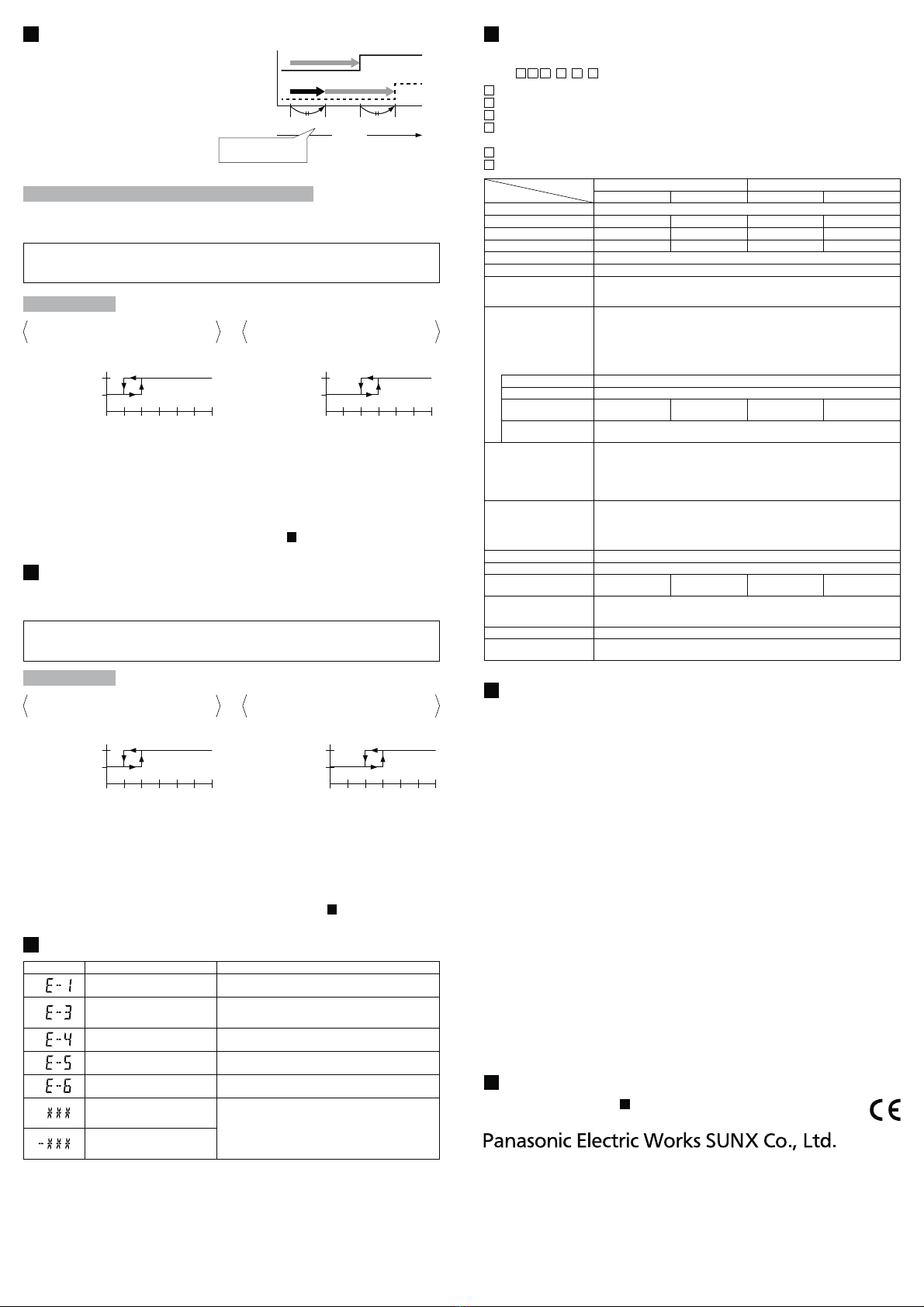
ERROR INDICATION
Error message Cause Corrective action
The load is short-circuited causing
Turn the power OFF and check the load.
Pressure is applied during zero-
point adjustment.
Applied pressure at the pressure port should be brought to
atmospheric pressure and zero-point adjustment should be
done again.
External input is carried out outside
the rated pressure range.
Applied pressure range should be brought within the rated
pressure range.
Communication error
(Disconnection, faulty connection, etc.)
Check the wiring when using the copy function.
Communication error
(Incorrect model.)
when using the copy function.
The applied pressure exceeds the
upper limit of the display pressure
range. Applied pressure range should be brought within the rated
pressure range.
The applied pressure exceeds the
lower limit of the display pressure
range.
When other error massage is displayed, contact us.
http://panasonic-electric-works.net/sunx
2431-1 Ushiyama-cho, Kasugai-shi, Aichi, 486-0901, Japan
Phone: +81-568-33-7861 FAX: +81-568-33-8591
Europe Headquarter: Panasonic Electric Works Europe AG
Rudolf-Diesel-Ring 2, D-83607 Holzkirchen, Germany
Phone: +49-8024-648-0
US Headquarter: Panasonic Electric Works Corporation of America
629 Central Avenue New Providence, New Jersey 07974 USA
Phone: +1-908-464-3550
PRINTED IN JAPAN © Panasonic Electric Works SUNX Co., Ltd. 2011


 User manual")


 User manual")


 User manual")