Connection
Environment
Where measurement conditions have not been specified precisely, the conditions used were an
ambient temperature of +20°C.
2) This value was obtained at a constant +25°C.
3) The value is in the range from 20 to 60% of the maximum detection distance with a combination of
sensor head and controller.
4) When using the BCD output unit GP-XBCD, the analog voltage output of a controller becomes invalid.
5) Adjusted to a 0 and +5V factory setting.
Power Supply
Wiring
Compatibility
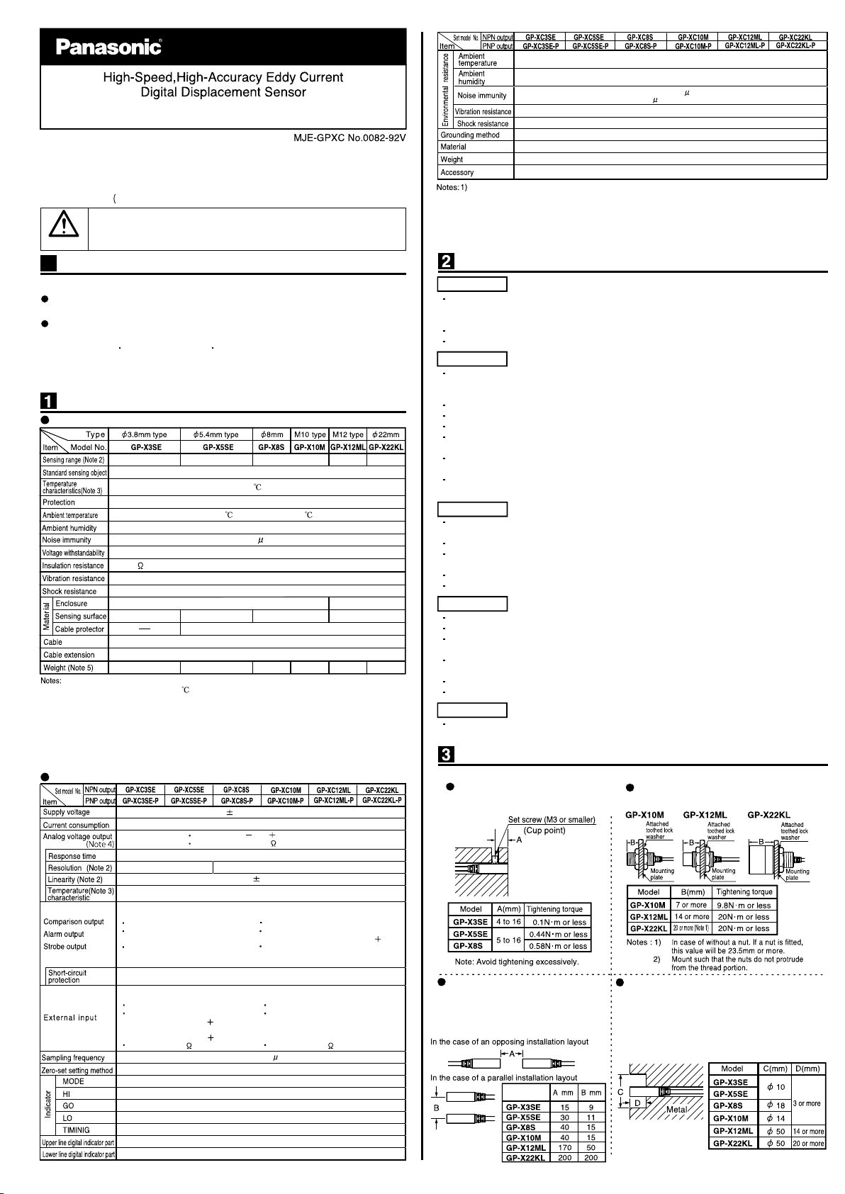
Distance from surrounding metal
As metal around the sensor may affect the detection,
take care of the following.
<Embedding of the sensor in metal>
Measurement value or analogue voltage output may be
changed if the sensor is completely embedded in metal.
Keep the minimum distance specified in the table below.
If sensor heads are mounted close
together without using the interference
prevention function, reserve the distance
specified below.
Thank you for purchasing our product. Be sure to read this manual before use in order to
ensure the safe and proper operation of this product. Keep this manual at hand for your
reference after reading it through. For details, refer to the GP-X Series User's Manual to make
settings for use. For the new info of the product and new version of the user’s manual, please
check our website https://panasonic.net/id/pidsx/global).
This product is to inspect (discriminate/measure) sensing objects. Never use
this product for prevention of accidents which damage a human life or
properties or for safety maintenance.
WARNING
Check the following items before using this product.
Controller Type(Product Name)
Check the model number on the top of the controller.
Bundled Items
Make sure that the following items are in the package.
• Controller × 1 Mounting frame × 1 Sensor head × 1
• Hexagonal nut × 2 (For GP-X10M, GP-X12ML and GP-X22KL only)
• Toothed washer × 1 (For GP-X10M, GP-X12ML and GP-X22KL only)
• Instruction Manual (This publication) × 1
Getting Started
Mounting Method
0.075ms (Fastest)
0.02% F.S. (64 times average processing)
0.04% F.S. (64 times average)
Within 0.3% F.S.
Output voltage: 5 to 5V (Note 5)
Output impedance: 100 approx.
150mA or less
24V DC 10% Ripple P-P 10% or less
5 digit green LED (display of numerical values within the upper and lower limit value)
5 digit orange LED (display of numerical values out of the upper and lower limit value)
Orange LED (lights up in mode status)
Orange LED (lights up when the upper value is exceeded)
Green LED (lights up when within the upper and lower limit value)
Green LED (lights up as per the external or internal trigger timing)
Push button setting/External input setting
40kHz (25 s)
Incorporated
Orange LED (lights up when less than the lower limit value)
<PNP output type>
Photo coupler input
Input current: 9mA or less
Operating voltage: ON voltage 17V or more
(between 0V and input)
OFF voltage 4V or less
(between 0V and input)
Input impedance: 5k approx.
<NPN output type>
Photo coupler input
Input current: 9mA or less
Operating voltage: ON voltage 17V or more
(between 24V and input)
OFF voltage 4V or less
(between 24V and input)
Input impedance: 5k approx.
<NPN output type>
NPN open-collector transistor
Maximum sink current: 100mA
Applied voltage: 30V DC or less
(between output and 0V)
Residual voltage: 1.6V or less
(at 100mA sink current)
0.4V (at 16mA sink current)
<PNP output type>
PNP open-collector transistor
Maximum source current: 100mA
Applied voltage: 30V DC or less
(between output and V)
Residual voltage: 1.6V or less
(at 100mA source current)
0.4V (at 16mA source current)
0.07% / F.S./°C or less
The GP-X series is configured to satisfy the specification with the combination of the sensor head
and the controller. Use the sensor head and controller in combination without fail; with other
combinations, not only may the specifications may not be satisfied but also failure may result.
Turn the controller off before mounting or removing the sensor head and controller.
Note that the cables will be damaged if they are pulled.
Wait 15 minutes (or 20 minutes with GP-X3S and GP-X5S) after the power is turned on before
operation is started. There may be a variation in the measurements immediately after power-on
because the power circuit is not stable.
There is a muting time of about two seconds after the power is turned on.
Take care that wrong wiring may damage the sensor.
Verify that the supply voltage variation is within the rating.
If power is supplied from a commercial switching regulator, ensure that the frame ground (F.G.)
terminal of the power supply is connected to an actual ground.
Make sure to use an isolation transformer for the DC power supply. If an auto-transformer
(single winding transformer) is used, this product or the power supply may get damaged.
In case a surge is generated in the used power supply, connect a surge absorber to the supply
and absorb the surge.
Do not run the wires together with high-voltage lines or power lines or put them in the same
raceway. This can cause malfunction due to induction.
Make sure that the power supply is off while wiring.
The analog voltage output is incorporated with a short circuit protection circuit. Do not connect
it directly to a power supply or a capacitive load.
Be careful to avoid statically charging connectors during wiring work. A failure may result.
Use the exclusive extension cable for cable extension of the sensor head.(Overall length: 10m)
This product has been developed / produced for industrial use only.
Avoid dust, dirt, and steam.
Take care that the sensor does not come in direct contact with water, oil, grease, or organic
solvents, such as, thinner, etc.
In case noise generating equipment (switching regulator, inverter motor, etc.) is used in the vicinity
of this product, connect the frame ground (F.G.) terminal of the equipment to an actual ground.
Take care that stress is not directly applied to the cable joint.
This sensor is for indoor use only.
In case the sensor head is broken, the sensor head replacement is possible with same model.
(However, entering a characteristics code (ID code) and calibration are required)
Tighten the sensor head to the torque specified below.
Mounting with set screw
<Column type>
Use an M3, or less, cup-point set screw.
Mounting with nut
<Screw type>
Precautions
In case the interference prevention
function is not used
Main Specifications
1) Where measurement conditions have not been specified precisely, the conditions used were
an ambient temperature of +20 .
2) The sensing range is specified for the standard sensing object.
3) The value represents 20 to 60% of the maximum sensing distance when combining the sensor
head and controller.
4) For the flexible cable type, please contact our office.
5) The given weight of the threaded type sensor head is value including the weight of the nut and
toothed lock washer.
6) If using the sensor in an environment where cutting oil droplets splatter, the sensor may be
deteriorated due to added substances in the oil. Please check the resistivity of the sensor against
the cutting oil you are using beforehand.
Power supply line: 1,000Vp, 10ms cycle, 0.5 s pulse width
Radiation: 300Vp, 10ms cycle, 0.5 s pulse width (with noise simulator)
ATA4811 (Controller mounting bracket): 1 set
Enclosure: Polycarbonate
Floating earth
120g approx.
35 to 85%RH, Storage: 35 to 85%RH
10 to 55Hz frequency, 0.75mm amplitude in X, Y and Z directions for two hours each
100m/s2 acceleration (10G approx.) in X, Y and Z directions five times each
Contoroller
Sensor head
80g approx.
45g approx.50g approx.40g approx.
40g approx.40g approx.
Connector attached high frequency coaxial cable, 3m long
(Note 4)
Extension up to 10m is possible with the optional cable
PP
PAABSPARABS
Brass (Nickel plated)Stainless steel (SUS303)
0 to 10mm
0 to 5mm0 to 2mm0 to 1mm0 to 0.8mm
Stainless steel (SUS304)/ Iron sheet [Cold rolled carbon steel (SPCC)] 60 x 60 x t 1 mm
0.07%F .S ./ or less
IP67 (IEC) , IP67G (Note6)
-10 to +55 , Storage: -20 to +70
35 to 85% RH, Storage: 35 to 85% RH
250V AC for one min. between all supply terminals connected together and enclosure
Power line: 300Vp 10ms cycle,and 0.5 s pulse width (with noise simulator)
20M ,or more, with 250V DC megger between all supply terminals connected together and enclosure
10 to 150 Hz frequency, 0.75mm amplitude, in X, Y and Z directions for two hours each
500m/s2 acceleration (50G approx.) in X, Y and Z directions for five times each
0 to+50°C (No dew condensation), Storage: 0 to+50°C
GP-X Series
INSTRUCTION MANUAL
Model no. of
sensor head
( ) ( )


 User manual")


 User manual")


