manuals.online logo
Brands
  1. Home
  2. •
  3. Brands
  4. •
  5. Panasonic
  6. •
  7. Accessories
  8. •
  9. Panasonic HG-S1010R User manual

Panasonic HG-S1010R User manual

INSTRUCTION MANUAL
Contact-Type Digital Displacement Sensor / Sensor Head
+*6Ƒ
MJE-HGS1010 No.0074-49V
Thank you very much for purchasing Panasonic products. Read this Instruction Man-
ual carefully and thoroughly for the correct and optimum use of this product. Kindly
keep this manual in a convenient place for quick reference.
WARNING
ƔNever use this product as a device for personnel protection.
ƔWhen using devices for personnel protection, use products that meet the laws
and standards for personnel protection that apply in each region or country, such
as OSHA, ANSI and IEC.
This document provides a brief summary of mounting and other related information.
For detailed information, refer “our web site (https://panasonic.net/id/pidsx/global) ”
.
1STANDARDS AND REGULATIONS
ƔThis product conforms to the standards and regulations below.
<European Directives>
EMC Directive
2CONTENTS OF PACKAGE
Sensor head 1 pc.
Mounting nut 1 pc.
Sensor head fastening wrench 1 pc.
Rubber bellows (+*6Ƒ5 only) 1 pc.
Instruction Manual (English / Japanese, Chinese / Korean) 2 pcs.
General Information for Safety, Compliance, and Instructions(23 languages)
1 pc.
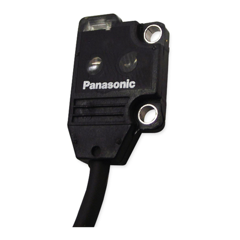
3DESCRIPTION OF PARTS
Sensor head connection cable connector
Operation indicator (Orange / Green)
Mounting nut
Rubber bellows
Probe
4MOUNTING
ƔWhen tightening the mounting nut, take care not to damage the rubber bellows.
ƔIf the rubber bellows is deformed, a load will occur when the spindle operates
and damage may result.
Ɣ
1RWHWKDWWKHPRXQWLQJGLUHFWLRQRIWKHSURYLGHGPRXQWLQJQXWGLႇHUVDFFRUGLQJ
to the thickness of the housing.
1. Open a hole in the housing in which the sen-
sor head will be mounted.
Mounting hole Housing thickness
HG-S1010RࠊHG-S1110Rø8H7 㸩0.015
0mm 6.5㹼12.5mm
HG-S1032 ø12H7 㸩0.018
0mm 6.5㹼10.5mm
HG-S1050 6.5㹼12.5mm
2. Insert the sensor head into the hole you
opened in the housing, and fasten lightly
with the provided mounting nut.
Housing thickness
Mounting hole
Mounting nut
(Accessory)
Installation of mounting nut attachment
Housing thickness
AB
HG-S1010RࠊHG-S1110R6.5㹼10mm 10㹼12.5mm
HG-S1032 6.5㹼8.5mm 8.5㹼10.5mm
HG-S1050 8.5㹼12.5mm
3. Fasten the sensor head.
When fastening the sensor head, tighten the
mounting nut with a wrench while holding the
sensor head in place with the sensor head
fastening wrench as shown at right.
Tighten to a torque of 12.5N·m or less
(HG-S1032 / HG-S1050: 15N·m or less).
4. Make sure that the rubber bellows has not
become deformed as shown at right.
If the rubber bellows is deformed, restore the
normal shape by rotating the bellows or oth-
erwise.
Connecting the sensor head connection cable
ƔWhen attaching the connector, make sure it is firmly tightened. If loose, the
FRQQHFWRUPD\FRPHRႇDQGFDXVHDQHUURU
ƔWhen disconnecting, always make sure that the fastening ring has been com-
pletely loosened before pulling out the cable.
Risk of damage if you pull the cable with excessive force (15N or more) with the
fastening ring tightened.
How to connect
1. Insert the sensor head connection
cable into the connector for the
sensor head connection cable on
the sensor head.
2. Turn the fastening ring on the sen-
sor head connector in the direction
VKRZQWR¿UPO\WLJKWHQWKHULQJ
How to remove
1. Turn the fastening ring on the sen-
sor head connector in the direction
shown to loosen the ring.
2. Grasp the connector and pull up to
remove the cable. 2. Pull out
1. Loosen
5SPECIFICATIONS
Type
10mm type
General purpose High precision
Standard type
Low measuring
force type
Standard type
Low measuring
force type
Model No. HG-S1010 HG-S1010R HG-S1110 HG-S1110R
Position detection method Optical absolute linear encoder method
Measurement range 10mm
Stroke 10.5mm or more
Measur-
ing force
(Note 1)
(Note 2)
Downward
mount
1.65N or less
1.10N (Note 3)
0.35N or less
0.30N (Note 3)
1.65N or less
1.10N (Note 3)
0.35N or less
0.30N (Note 3)
Upward mount 1.35N or less
0.85N (Note 3)
-
1.35N or less
0.85N (Note 3)
-
Side mount 1.50N or less
0.95N (Note 3)
0.25N or less
0.20N (Note 3)
1.50N or less
0.95N (Note 3)
0.25N or less
0.20N (Note 3)
Resolution 0.5μm0.1μm
Sampling cycle 1ms
Indication
accuracy
(P-P)
Full range 2.0μm or less 1.0μm or less
Limited range
1.0μm or less (any 60μm) 0.5μm or less (any 60μm)
Hot swap function Incorporated
Protective structure IP67 (IEC) (Note 4)
-
IP67 (IEC) (Note 4)
-
Ambient temperature -10 to +55°C (No dew condensation or icing allowed), Storage: -20 to +60°C
Ambient humidity 35 to 85% RH, Storage: 35 to 85% RH
Mechanical life (Note5) 100 million times or more (reference value)
Tip deviation amount 35μm (typical value)
Grounding method Capacitor grounding
Material
Body: Zinc, Holder: Stainless steel,
Spindle: Tool steel, Probe: Ceramic, Rubber
bellows: NBR (black)
Weight (main unit only) Approx. 80g
1RWHV0HDVXUHGDWDQDPELHQWWHPSHUDWXUHRI&XQOHVVRWKHUZLVHVSHFL¿HG
2)
+*6Ƒ5 is standard state without the rubber bellows.
3) Typical value near center of measurement.
4) Excludes damage and deterioration to the rubber bellows due to external causes.
5) Typical value in a clean environment in which there is no contact with liquids such as water or oil, and no set-
tling of particulate matter.
Mounting nut with the
thread facing up
B
Housing
Thread
Mounting nut with the
thread facing down
A
Housing
Thread
Sensor head
fastening wrench
(Accessory)
Wrench
1. Insert
2. Tighten
fastening ring
Type
32mm type 50mm type
General purpose
Standard type
Model No. HG-S1032 HG-S1050 (Note 1)
Position detection method Optical absolute linear encoder method
Measurement range 32mm 50mm
Stroke 32.5mm or more 50.5mm or more
Measur-
ing force
(Note 2)
Downward
mount
2.97N or less
1.90N (Note 3)
3.80N or less
1.90N (Note 3)
Upward mount 2.09N or less
1.19N (Note 3)
3.20N or less
1.40N (Note 3)
Side mount 2.53N or less
1.50N (Note 3)
3.40N or less
1.70N (Note 3)
Resolution 0.5μm
Sampling cycle 1ms
Indication
accuracy
(P-P)
Full range 3.0μm or less 3.5μm or less
Limited range
2.0μm or less (any 60μm)
-
Hot swap function Incorporated
Protective structure IP67 (IEC) (Note 4)
Ambient temperature -10 to +55°C (No dew condensation or icing allowed), Storage: -20 to +60°C
Ambient humidity 35 to 85% RH, Storage: 35 to 85% RH
Mechanical life (Note 5) 30 million times or more
(reference value)
10 million times or more
(reference value)
Tip deviation amount 40μm (typical value)
Grounding method Capacitor grounding
Material
Body: Aluminium, Holder: Free-cutting steel ,
Spindle: Tool steel, Probe: Ceramic,
Rubber bellows: NBR (black)
Weight (main unit only) Approx. 150g Approx. 180g
Notes: 1) Connect to an HG-SC series controller manufactured in February 2019 or later.
 0HDVXUHGDWDQDPELHQWWHPSHUDWXUHRI&XQOHVVRWKHUZLVHVSHFL¿HG
3) Typical value near center of measurement.
4) Excludes damage and deterioration to the rubber bellows due to external causes.
5) Typical value in a clean environment in which there is no contact with liquids such as water or oil, and no set-
tling of particulate matter.
6CAUTIONS
The special sensor head +*6Ƒ is designed to be used with the controller
+*6&Ƒ,IXVHGZLWKRWKHUWKDQWKHVSHFLDOVHQVRUKHDGRSWLRQWKHVSHFL¿FDWLRQV
will not be met and product malfunctioning or damage may occur.
ƔThis device has been developed / produced for industrial use only.
Ɣ'RQRWXVHWKLVSURGXFWRXWVLGHWKHUDQJHRIWKHVSHFL¿FDWLRQV5LVNRIDQDFFLGHQW
and product damage. There is also a risk of a noticeable reduction of service life.
ƔDeviations may occur in the measured value at the bottom dead point. Do not use
the bottom dead point as a standard.
ƔDo not wire in parallel with a high-voltage line or power line, or run through the
same conduit. Risk malfunctioning due to induction.
Ɣ 9HULI\WKDWWKHVXSSO\YROWDJHÀXFWXDWLRQVDUHZLWKLQWKHUDWLQJ
ƔIf power is supplied from a commercial switching regulator, ensure that the frame
ground (F.G.) terminal of the power supply is connected to an actual ground.
ƔDo not use during the initial transient time after the power supply is switched ON.
Ɣ
Do not apply stress such as excessive bending or pulling to the extracted part of a cable.
ƔWhen attaching the sensor head connection cable to this product, do not apply
force to the product.
ƔOnly one joint (optional) can be installed to one sensor head.
ƔIf the
Low measuring force type
(HG-S1010R/HG-S1110R) is mounted in a lateral
position and used with a roller-type probe (HG-SS40U, optional), the joint (option-
al) cannot be used.
ƔThis product is suitable for indoor use only.
ƔAvoid dust, dirt, and steam.
Ɣ
Do not use this sensor in places where it may come in contact with corrosive gas, etc.
Ɣ
Ensure that the product does not come into contact with organic solvents such as thinner.
ƔEnsure that the product does not come into contact with strong acid or alkaline.
ƔEnsure that the product does not come into contact with oil or grease.
Ɣ
7KLVSURGXFWFDQQRWEHXVHGLQDQHQYLURQPHQWFRQWDLQLQJÀDPPDEOHRUH[SORVLYHJDVHV
Ɣ 3HUIRUPDQFHPD\QRWEHVDWLVIDFWRU\LQDVWURQJHOHFWURPDJQHWLF¿HOG
ƔThis product is a precision device. Do not drop or otherwise subject to shock. Risk
of product damage.
ƔDo not allow excessive horizontal force to be applied to the spindle. This may
cause reduced accuracy and durability.
ƔThe standard rubber bellows is a consumable part. Replace it regularly as a pre-
ventive maintenance.The rubber bellows can deteriorate quickly depending on
usage environment. If it deteriorates, it generates cracks and other problems,
causing dust and water to enter and resulting in a malfunction.
ƔNever remove the standard rubber bellows except for replacement.
5LVNRISURGXFWGDPDJHGXHWRLQ¿OWUDWLRQE\GXVWZDWHURURWKHUFRQWDPLQDQWV
ƔWhen the product becomes unusable or unneeded, dispose of the product appro-
priately as industrial waste.
ƔNever attempt to disassemble, repair, or modify the product.
7MAINTENANCE
How to replace the probe
Ɣ
Always secure the spindle to prevent rotation before replacing the probe. Risk of
product damage if an excessive torque (0.2N·m or more) is applied to the spindle.
ƔIf the rubber bellows is damaged or deformed during probe replacement, the
VSHFL¿FDWLRQVRIWKHSURWHFWLYHVWUXFWXUHPD\QRWEHVDWLV¿HG
1. Turn the probe screw in the direction of the arrow and remove the probe from the
spindle. When turning the probe screw, hold the cut face of the spindle with the
provided sensor head fastening wrench to prevent the spindle from turning.
Hold the sensor head fastening wrench in place, and turn only the probe.
Sensor head
fastening wrench
(Accessory)
Probe
Turn
2. Attach the new probe to the spindle. The tightening torque
should be 0.4N·m or less. Make sure that the probe does
not come OFF.
When turning the probe screw, hold the cut face of the
spindle with the provided sensor head fastening wrench to
prevent the spindle from turning.
Hold the sensor head fastening wrench in place, and turn
only the probe. Turn
3.
After attaching the probe, wipe the spindle with absolute alcohol to remove any dirt.
How to replace the rubber bellows
ƔWhen replacing the rubber bellows, take care that no dirt or other contaminants
get on the spindle. Risk of malfunctioning. If any dirt gets on the spindle, wipe
clean with absolute alcohol. Do not allow the rubber bellows to become twisted
during attachment.
ƔNote that the measuring force will vary depending on the attachment state of the
rubber bellows.
ƔIf the rubber bellows is deformed, a load will occur when the spindle operates
and damage may result.
1. Turn the probe screw in the direction of the arrow and remove the probe from the
spindle. When turning the probe screw, hold the cut face of the spindle with the
provided sensor head fastening wrench to prevent the spindle from turning.
Hold the sensor head fastening wrench in place, and turn only the probe.
Sensor head
fastening wrench
(Accessory)
Probe
Turn
2. Remove the rubber bellows from the spindle.
Rubber bellows (Option)
3. Fit the new rubber bellows onto the spindle.
Insert to the top edge of the spindle as
shown at right.
Insert to top edge
4. 3XVKWKHUXEEHUEHOORZVXSZLWK\RXU¿QJHU
until the tip of the spindle is exposed as
shown at right.
Spindle tip
5. Attach the probe to the spindle. The tighten-
ing torque should be 0.4N·m or less. Make
sure that the probe does not come OFF.
When turning the probe screw, hold the cut
face of the spindle with the provided sensor
head fastening wrench to prevent the spindle
from turning.
Hold the sensor head fastening wrench in
place, and turn only the probe.
Turn
6. Make sure that the rubber bellows has not
become deformed as shown at right.
If the rubber bellows is deformed, restore the
normal shape by rotating the bellows or oth-
erwise.
Panasonic Industrial Devices SUNX Co., Ltd.
https://panasonic.net/id/pidsx/global
Please visit our website for inquiries and about our sales network.
PRINTED IN JAPAN © Panasonic Industrial Devices SUNX Co., Ltd. 2020
This manual suits for next models

4

Other Panasonic Accessories manuals

Panasonic MA4X159A User manual

Panasonic

Panasonic MA4X159A User manual

Panasonic CF-VNP016 User manual

Panasonic

Panasonic CF-VNP016 User manual

Panasonic KX-HNS101C User manual

Panasonic

Panasonic KX-HNS101C User manual

Panasonic MA3X704 User manual

Panasonic

Panasonic MA3X704 User manual

Panasonic MA3S133 (MA133) User manual

Panasonic

Panasonic MA3S133 (MA133) User manual

Panasonic MA2S7280G User manual

Panasonic

Panasonic MA2S7280G User manual

Panasonic MA26111 User manual

Panasonic

Panasonic MA26111 User manual

Panasonic WX-LA20 User manual

Panasonic

Panasonic WX-LA20 User manual

Panasonic KX-HNS103AZ User manual

Panasonic

Panasonic KX-HNS103AZ User manual

Panasonic MA4Z7130G User manual

Panasonic

Panasonic MA4Z7130G User manual

Panasonic EX-21 Series User manual

Panasonic

Panasonic EX-21 Series User manual

Panasonic WV-PB5504A User manual

Panasonic

Panasonic WV-PB5504A User manual

Panasonic MAZLxxxH Series User manual

Panasonic

Panasonic MAZLxxxH Series User manual

Panasonic UE-608050 User manual

Panasonic

Panasonic UE-608050 User manual

Panasonic WV-PB5508 User manual

Panasonic

Panasonic WV-PB5508 User manual

Panasonic EE23 User manual

Panasonic

Panasonic EE23 User manual

Panasonic LS-H A Series User manual

Panasonic

Panasonic LS-H A Series User manual

Panasonic LS-400 Series User manual

Panasonic

Panasonic LS-400 Series User manual

Panasonic FZ-VNPN11U User manual

Panasonic

Panasonic FZ-VNPN11U User manual

Panasonic WX-LA20 User manual

Panasonic

Panasonic WX-LA20 User manual

Panasonic SR-CN108 User manual

Panasonic

Panasonic SR-CN108 User manual

Panasonic MA2S077G User manual

Panasonic

Panasonic MA2S077G User manual

Panasonic MA2J7290G User manual

Panasonic

Panasonic MA2J7290G User manual

Panasonic PD50 User manual

Panasonic

Panasonic PD50 User manual

Popular Accessories manuals by other brands

IFM efector 200 OGH operating instructions

IFM

IFM efector 200 OGH operating instructions

Clearaudio TT3 user manual

Clearaudio

Clearaudio TT3 user manual

Furuno DRS12A X-Class installation manual

Furuno

Furuno DRS12A X-Class installation manual

Leviton 8200 quick guide

Leviton

Leviton 8200 quick guide

ST X-NUCLEO-53L1A2 Detailed Quick Start Guide

ST

ST X-NUCLEO-53L1A2 Detailed Quick Start Guide

Veris Industries AA01 installation guide

Veris Industries

Veris Industries AA01 installation guide

Countbox STD-1 Installation and setup guide

Countbox

Countbox STD-1 Installation and setup guide

XLAYER X-Pro user guide

XLAYER

XLAYER X-Pro user guide

opticis M1-2R2H-TR user manual

opticis

opticis M1-2R2H-TR user manual

PROZIS Essence user manual

PROZIS

PROZIS Essence user manual

KooPower DQ-608 user manual

KooPower

KooPower DQ-608 user manual

StarTech.com ST122HD20 quick start guide

StarTech.com

StarTech.com ST122HD20 quick start guide

MTD OEM-190-604 Operator's manual

MTD

MTD OEM-190-604 Operator's manual

XD COLLECTION P324.76 Series manual

XD COLLECTION

XD COLLECTION P324.76 Series manual

Waveshare VL53L1X user manual

Waveshare

Waveshare VL53L1X user manual

Omron F210 Setup manual

Omron

Omron F210 Setup manual

Pilz PSEN sl-1.0p 6.1 operating manual

Pilz

Pilz PSEN sl-1.0p 6.1 operating manual

LEGRAND 34063 manual

LEGRAND

LEGRAND 34063 manual

manuals.online logo
manuals.online logoBrands
  • About & Mission
  • Contact us
  • Privacy Policy
  • Terms and Conditions

Copyright 2025 Manuals.Online. All Rights Reserved.