-
4
-
(K)
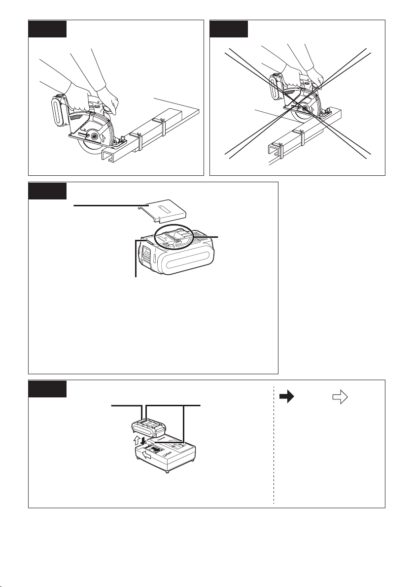
Battery pack
Akkupack
Batterie autonome
Pacco batteria
Accu
Batería
Batteripakning
Batteri
Batteri
Akku
Pil takımı
(L)
Storage slot for hex wrench
Schlüsseldepot
Fente de rangement de clé hexagonale
Fessura di custodia della chiave esagonale
Opberggleuf voor zeskantsleutel
Ranura para guardar la llave hexagonal
Holder til fastnøgle
Förvaringsspår för insexnyckel
Lagringsslisse for sekskantnøkkel
Kuusioavaimen säilytyslokero
Altıgen somun anahtarı saklama yarığı
(M)
Battery pack alignment mark
Akku-Ausrichtmarke
Marque d’alignement de la batterie autonome
Marcatura allineamento pacco batteria
Uitlijnteken voor accu
Marca de alineamiento del paquete de las baterías
Mærke til indretning af batteripakning
Anpassningsmärke för batteri
Innrettingsmerke for batteriet
Akun sovitusmerkki
Akü hizalama işareti
(N)
Battery pack release button
Akku-Entriegelungsknopf
Bouton de libération de batterie autonome
Tasto di rilascio blocco batteria
Ontgrendelknop voor accu
Botón de liberación de la batería
Udløserknap til batteripakning
Frigöringsknapp för batteri
Frigjøringsknapp for batteriet
Akun vapautuspainike
Pil takımı serbest bırakma düğmesi
(O)
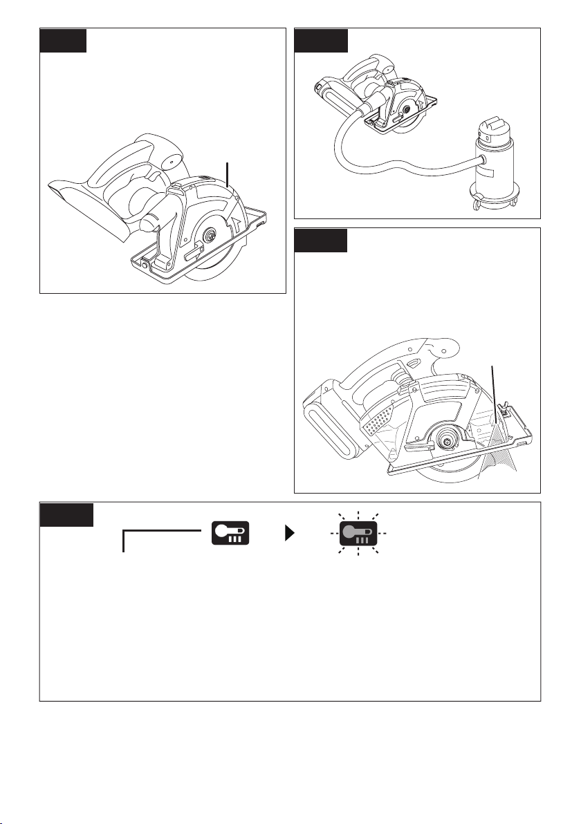
Control panel
Bedienfeld
Panneau de commande
Pannello di controllo
Bedieningspaneel
Panel de control
Kontrolpanel
Manöverpanel
Betjeningspanel
Merkkivalopaneeli
Kumanda paneli
(P)
Depth adjustment nut
Tiefeneinstellmutter
Ecrou d’ajustement de la profondeur
Dado di regolazione della profondità
Diepte-instelmoer
Tuerca de ajuste de profundidad
Dybdeindstillingsmøtrik
Djupinställningsratt
Dybdejusteringsspake
Syvyyden säätömutteri
Derinlik ayarlama somunu
(Q)
LED light
LED-Leuchte
Lumière DEL
Luce LED
LED-lampje
Luz indicadora
LED-lys
LED-ljus
LED-lys
LED-valo
LED ışığı
(R)
Spindle lock button
Spindelarretierknopf
Bouton de verrouillage de broche
Tasto di blocco albero
Asblokkeerknop
Botón de bloqueo del husillo
Aksellåseknap
Låsknapp för spindel
Knapp for aksellås
Karan lukituspainike
Mil kilit tuşu
(S)
Overheat warning lamp (battery)
Überhitzungs-Warnlampe (Akku)
Témoin d’avertissement de surchauffe (batterie)
Spia avvertenza surriscaldamento (batteria)
Oververhitting-waarschuwingslampje (accu)
Luz de advertencia de sobrecalentamiento (batería)
Advarselslamp til overophedning (batteri)
Varningslampa för överhettning (batteri)
Varsellampe for overheting (batteri)
Ylikuumenemisen varoituslamppu (akku)
Aşırı ısınma uyarı lambası (batarya)
(T)
Battery low warning lamp
Akkuladungs-Warnlampe
Témoin d’avertissement de batterie basse
Spia avvertenza batteria scarica
Accuspanning-waarschuwingslampje
Luz de aviso de baja carga de batería
Advarselslampes batterieffekt lav
Varningslampa för svagt batteri
Varsellampe for lavt batteri
Alhaisen akkutehon varoituslamppu
Düşük pil uyarı lambası
EY45A2(EU).indb 4 2016-4-14 11:16:39