Panasonic EY45A2 User manual

Cordless Multi Purpose Cutter
Akku-Mehrzwecksäge
Scie circulaire polyvalente sans l
Cesoia Senza Fili Multiuso
Snoerloze universele zaagmachine
Sierra de propósitos múltiples inalámbrica
Akku-multifunktionsskærer
Sladdlös universalcirkelsåg
Oppladbar Multi-kutter
Ladattava monitoimileikkuri
Model No: EY45A2
Before operating this unit, please read these instructions completely and save this manual for future use.
Vor Inbetriebnahme des Gerätes die Betriebsanleitung bitte gründlich durchlesen und diese Broschüre zum späteren Nachschlagen sorgfältig aufbewahren.
Lire entièrement les instructions suivantes avant de faire fonctionner l’appareil et conserver ce mode d’emploi à des fins de consultation ultérieure.
Prima di usare questa unità, leggere completamente queste istruzioni e conservare il manuale per usi futuri.
Lees deze gebruiksaanwijzing aandachtig door voor u het apparaat in gebruik neemt en bewaar de gebruiksaanwijzing voor eventuele naslag.
Antes de usar este aparato por primera vez, lea todas las instrucciones de este manual y guarde el manual para poderlo consultar en el futuro.
Gennemlæs denne betjeningsvejledning før brugen og gem den til fremtidig brug.
Läs igenom hela bruksanvisningen innan verktyget tas i bruk. Spara bruksanvisningen för senare användning.
Før enheten tas i bruk, vennligst les alle disse anvisningene og oppbevar deretter bruksanvisningen for senere bruk.
Lue ohjeet huolella ennen laitteen käyttöönottoa ja säilytä tämä käyttöohje tallessa tulevaa tarvetta varten.
Operating Instructions
Bedienungsanleitung
Instructions d’utilisation
Istruzioni per l’uso
Gebruiksaanwijzing
Manual de instrucciones
Brugsvejledning
Driftsföreskrifter
Bruksanvisning
Käyttöohjeet
EY45A2(EU).indb 1 2014-1-15 10:13:06

-
2
-
Index/Index/Index/Indice/Index/Indice/Indeks/Index/Indeks/Hakemisto
English: Page 6 Español: Página 93
Deutsch: Seite 23 Dansk: Side 110
Français: Page 41 Svenska: Sidan 127
Italiano: Pagina 59 Norsk: Side 144
Nederlands: Bladzijde 76 Suomi: Sivu 160
FUNCTIONAL DESCRIPTION
FUNKTIONSBESCHREIBUNG
DESCRIPTION DES FONCTIONS
DESCRIZIONE DELLE FUNZIONI
FUNCTIEBESCHRIJVING
DESCRIPCIÓN FUNCIONAL
FUNKTIONSBESKRIVELSE
FUNKTIONSBESKRIVNING
FUNKSJONSBESKRIVELSE
TOIMINTOJEN KUVAUS
*10.8 V ─ 28.8 V
(B)
(Q)(P)
(R)
(A)
(F)
(E)
(C)
(D)
(G)
(H)
(I)
(J)
(O)
(N)
(M)
(L)
(K)
(O)
(T)(S)
(U)
(V)
(W)
EY45A2(EU).indb 2 2014-1-15 10:13:06

-
3
-
(A)
Power switch
Betriebsschalter
Interrupteur d’alimentation
Interruttore di accensione
Hoofdschakelaar
Interruptor de alimentación
Afbryder
Startomkopplare
Strømbryter
Käyttökytkin
(B)
Switch lock lever
Schalter-Verriegelungshebel
Levier de verrouillage d’interrupteur
Levetta di blocco interruttore
Schakelaarblokkeerhendel
Palanca de bloqueo del interruptor
Afbyderlås
Omkopplarlås
Sperre for strømbryter
Käyttökytkimen lukitusvipu
(C)
Front grip
Vorderer Griff
Poignée avant
Impugnatura anteriore
Voorste greep
Empuñadura frontal
Forreste håndtag
Framgrepp
Fronthåndtak
Etukahva
(D)
Front cover
Frontabdeckung
Couvercle avant
Coperchio anteriore
Voorste afdekking
Cubierta frontal
Frontdæksel
Främre skyddskåpa
Frontdeksel
Etukansi
(E)
Transparent guard
Klarsichthaube
Protège-lame transparent
Protezione trasparente
Doorzichtige beschermkap
Protector transparente
Gennemsigtig skærm
Genomskinligt skydd
Gjennomsiktig bladskjerm
Läpinäkyvä suojus
(F)
Shoe
Gleitschuh
Sabot
Pattino
Schoen
Zapata
Skæreplade
Sko
Fot
Pöytä
(G)
Blade* (EY9PM13E)
Blatt (EY9PM13E)
Lame de scie (EY9PM13E)
Lama (EY9PM13E)
Zaagblad (EY9PM13E)
Cuchilla (EY9PM13E)
Blad (EY9PM13E)
Klinga (EY9PM13E)
Blad (EY9PM13E)
Terä (EY9PM13E)
(H)
Lower guard
Untere Schutzvorrichtung
Protecteur mobile inférieur de lame
Protezione inferiore
Onderste beschermkap
Protector inferior de la cuchilla
Nederste skærm
Undre skydd
Nedre beskyttelsesskjerm
Teräsuoja
(I)
Retracting handle
Rückzughebel
Poignée rétractable
Leva di ritorno
Terugtrekhendel
Mango retractable
Tilbagetrækningshåndtag
Uppfällningsspak
Tilbakeførbart håndtak
Teränsuojan vipu
(J)
Dust case
Staubgehäuse
Boîte à poussière
Raccoglipolvere
Stofhuis
Caja de polvo
Støvopsamler
Dammhuv
Støvdeksel
Pölykotelo
EY45A2(EU).indb 3 2014-1-15 10:13:06

-
4
-
(K)
Battery pack
Akkupack
Batterie autonome
Pacco batteria
Accu
Batería
Batteripakning
Batteri
Batteri
Akku
(L)
Storage slot for hex wrench
Schlüsseldepot
Fente de rangement de clé hexagonale
Fessura di custodia della chiave esagonale
Opberggleuf voor zeskantsleutel
Ranura para guardar la llave hexagonal
Holder til fastnøgle
Förvaringsspår för insexnyckel
Lagringsslisse for sekskantnøkkel
Kuusioavaimen säilytyslokero
(M)
Battery pack alignment mark
Akku-Ausrichtmarke
Marque d’alignement de la batterie autonome
Marcatura allineamento pacco batteria
Uitlijnteken voor accu
Marca de alineamiento del paquete de las baterías
Mærke til indretning af batteripakning
Anpassningsmärke för batteri
Innrettingsmerke for batteriet
Akun sovitusmerkki
(N)
Battery pack release button
Akku-Entriegelungsknopf
Bouton de libération de batterie autonome
Tasto di rilascio blocco batteria
Ontgrendelknop voor accu
Botón de liberación de la batería
Udløserknap til batteripakning
Frigöringsknapp för batteri
Frigjøringsknapp for batteriet
Akun vapautuspainike
(O)
Control panel
Bedienfeld
Panneau de commande
Pannello di controllo
Bedieningspaneel
Panel de control
Kontrolpanel
Manöverpanel
Betjeningspanel
Merkkivalopaneeli
(P)
Depth adjustment nut
Tiefeneinstellmutter
Ecrou d’ajustement de la profondeur
Dado di regolazione della profondità
Diepte-instelmoer
Tuerca de ajuste de profundidad
Dybdeindstillingsmøtrik
Djupinställningsratt
Dybdejusteringsspake
Syvyyden säätömutteri
(Q)
LED light
LED-Leuchte
Lumière DEL
Luce LED
LED-lampje
Luz indicadora
LED-lys
LED-ljus
LED-lys
LED-valo
(R)
Spindle lock button
Spindelarretierknopf
Bouton de verrouillage de broche
Tasto di blocco albero
Asblokkeerknop
Botón de bloqueo del husillo
Aksellåseknap
Låsknapp för spindel
Knapp for aksellås
Karan lukituspainike
(S)
Overheat warning lamp (battery)
Überhitzungs-Warnlampe (Akku)
Témoin d’avertissement de surchauffe (batterie)
Spia avvertenza surriscaldamento (batteria)
Oververhitting-waarschuwingslampje (accu)
Luz de advertencia de sobrecalentamiento (batería)
Advarselslamp til overophedning (batteri)
Varningslampa för överhettning (batteri)
Varsellampe for overheting (batteri)
Ylikuumenemisen varoituslamppu (akku)
(T)
Battery low warning lamp
Akkuladungs-Warnlampe
Témoin d’avertissement de batterie basse
Spia avvertenza batteria scarica
Accuspanning-waarschuwingslampje
Luz de aviso de baja carga de batería
Advarselslampes batterieffekt lav
Varningslampa för svagt batteri
Varsellampe for lavt batteri
Alhaisen akkutehon varoituslamppu
EY45A2(EU).indb 4 2014-1-15 10:13:07

-
5
-
(U)
Hex wrench
Inbusschlüssel
Clé hexagonale
Chiave esagonale
Zeskantsleutel
Llave hexagonal
Fastnøgle
Insexnyckel
Sekskantnøkkel
Kuusioavain
(V)
Battery charger
Ladegerät
Chargeur de batterie
Caricabatterie
Acculader
Cargador de la batería
Batterioplader
Batteriladdare
Batterilader
Akkulaturi
(
W
)
Battery pack cover
Akkuabdeckung
Couvercle de la batterie autonome
Coperchio pacco batteria
Accu-afdekking
Cubierta de batería
Pakningsdæksel
Batteriskydd
Batterideksel
Akun liitinsuoja
*Never use blades rated for speeds below that of main unit rpm.
EY45A2(EU).indb 5 2014-1-15 10:13:07

-
6
-
I
. INTRODUCTION
This tool is a Multi Purpose Cutter. By changing
the blade, it can be used to cut wood, metal, and
plastic. Dust can be collected by an integrated
dust case or via a connected vacuum (by
attaching the hose to the tool).
DANGER
This product is a cutting tool, designed to cut
through metal and wood. It has a rotating blade
which is capable of cutting you deeply, causing
serious injury or death. As a result, please read
this manual and the cautionary markings on the
tool carefully, and obey all of the Safety Instruc-
tions to avoid such injury.
WARNING
To avoid injury, never insert your finger or any
other object into any opening of the tool.
WARNING
Read all safety warnings and all instructions.
Failure to follow the warnings and instructions
may result in electric shock, fire and/or serious
injury.
How to Use This Manual
• Please read this manual completely before
starting to cut with your tool. If you let someone
else use the tool, make sure they either read this
manual or are fully instructed in the proper use
and all safety precautions concerning the tool.
• Please keep this manual for future reference. It
contains important safety information that you
must follow to use the tool safely.
• This manual and product use the following signal
words:
NOTE
Notes provide additional information that you
should know about the tool.
CAUTION
Caution indicates a potentially hazardous situ-
ation, which could result in minor or moderate
injury if not avoided. Cautions also alert you to
unsafe practices to be avoided.
WARNING
Warning indicates a potentially hazardous situa-
tion, which could result in serious injury or death
if not avoided.
DANGER
Danger indicates an imminent hazard which will
result in serious injury or death if not avoided.
Read “the Safety Instructions” booklet and
the following before using.
II
.
ADDITIONAL SAFETY
RULES
Safety instructions for all
saws
DANGER
1) Keep hands away from cutting area
and the blade. Keep your second hand
on auxiliary handle, or motor housing.
If both hands are holding the saw, they
cannot be cut by the blade.
2) Do not reach underneath the workpiece.
The guard cannot protect you from the
blade below the workpiece.
Original instructions: English
Translation of the original instructions:
Other languages
Read “the Safety Instructions” booklet
and the following before using.
EY45A2(EU).indb 6 2014-1-15 10:13:07

-
7
-
3) Adjust the cutting depth to the thickness
of the workpiece. Less than a full tooth of
the blade teeth should be visible below the
work-piece.
4) Never hold piece being cut in your hands
or across your leg. Secure the work piece
to a stable platform. It is important to
support the work properly to minimize body
exposure, blade binding, or loss of control.
5) Hold power tool by insulated gripping
surfaces when performing an operation
where the cutting tool may contact
hidden wiring or its own cord. Contact
with a “live” wire will also make exposed
metal parts of the power tool “live” and
shock the operator.
6) When ripping always use a rip fence or
straight edge guide. This improves the
ac-curacy of cut and reduces the chance of
blade binding.
7) Always use blades with correct size
and shape (diamond versus round) of
arbour holes. Blades that do not match
the mounting hardware of the saw will run
eccentrically, causing loss of control.
8) Never use damaged or incorrect blade
washers or bolt. The blade washers and
bolt were specially designed for your saw,
for optimum performance and safety of
operation.
Further safety instructions
for all saws
Causes and operator prevention of kick-
back:
- Kickback is a sudden reaction to a pinched,
bound or misaligned saw blade, causing
an uncontrolled saw to lift up and out of the
workpiece toward the operator;
- When the blade is pinched or bound tight-
ly by the kerf closing down, the blade stalls
and the motor reaction drives the unit rapidly
back toward the operator;
- If the blade becomes twisted or misaligned
in the cut, the teeth at the back edge of the
blade can dig into the top surface of the
wood causing the blade to climb out of the
kerf and jump back toward the operator.
Kickback is the result of saw misuse and/or
incorrect operating procedures or conditions and
can be avoided by taking proper precautions as
given below.
1) Maintain a firm grip with both hands on
the saw and position your arms to resist
kick-back forces. Position your body to
either side of the blade, but not in line
with the blade.
Kickback could cause the saw to jump back-
wards, but kickback forces can be controlled
by the operator, if proper precautions are
taken.
2) When blade is binding, or when interrupt-
ing a cut for any reason, release the trig-
ger and hold the saw motionless in the
material until the blade comes to a com-
plete stop. Never attempt to remove the
saw from the work or pull the saw back-
ward while the blade is in motion or kick-
back may occur.
Investigate and take corrective actions to
eliminate the cause of blade binding.
3) When restarting a saw in the workpiece,
center the saw blade in the kerf and check
that saw teeth are not engaged into the
material.
If saw blade is binding, it may walk up or kick-
back from the workpiece as the saw is restarted.
4) Support large panels to minimize the risk
of blade pinching and kickback.
Large panels tend to sag under their own
weight. Supports must be placed under the
panel on both sides, near the line of cut and
near the edge of the panel.
5) Do not use dull or damaged blades.
Unsharpened or improperly set blades pro-
duce narrow kerf causing excessive friction,
blade binding and kickback.
6) Blade depth and bevel adjusting locking
levers must be tight and secure before
making cut.
If blade adjustment shifts while cutting, it may
cause binding and kickback.
7) Use extra caution when making a “plunge
cut” into existing walls or other blind
areas.
The protruding blade may cut objects that
can cause kickback.
Safety instructions for this
saw
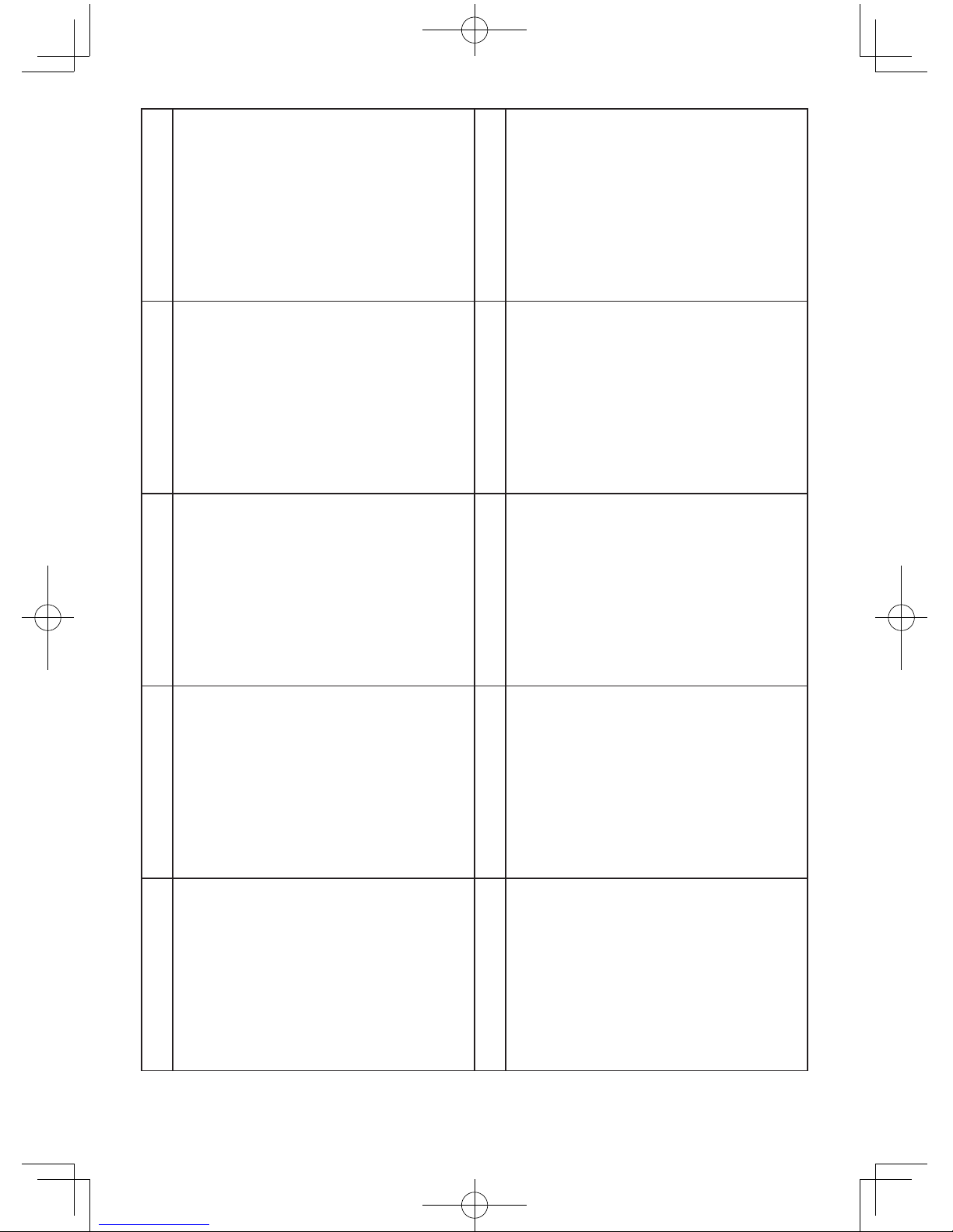
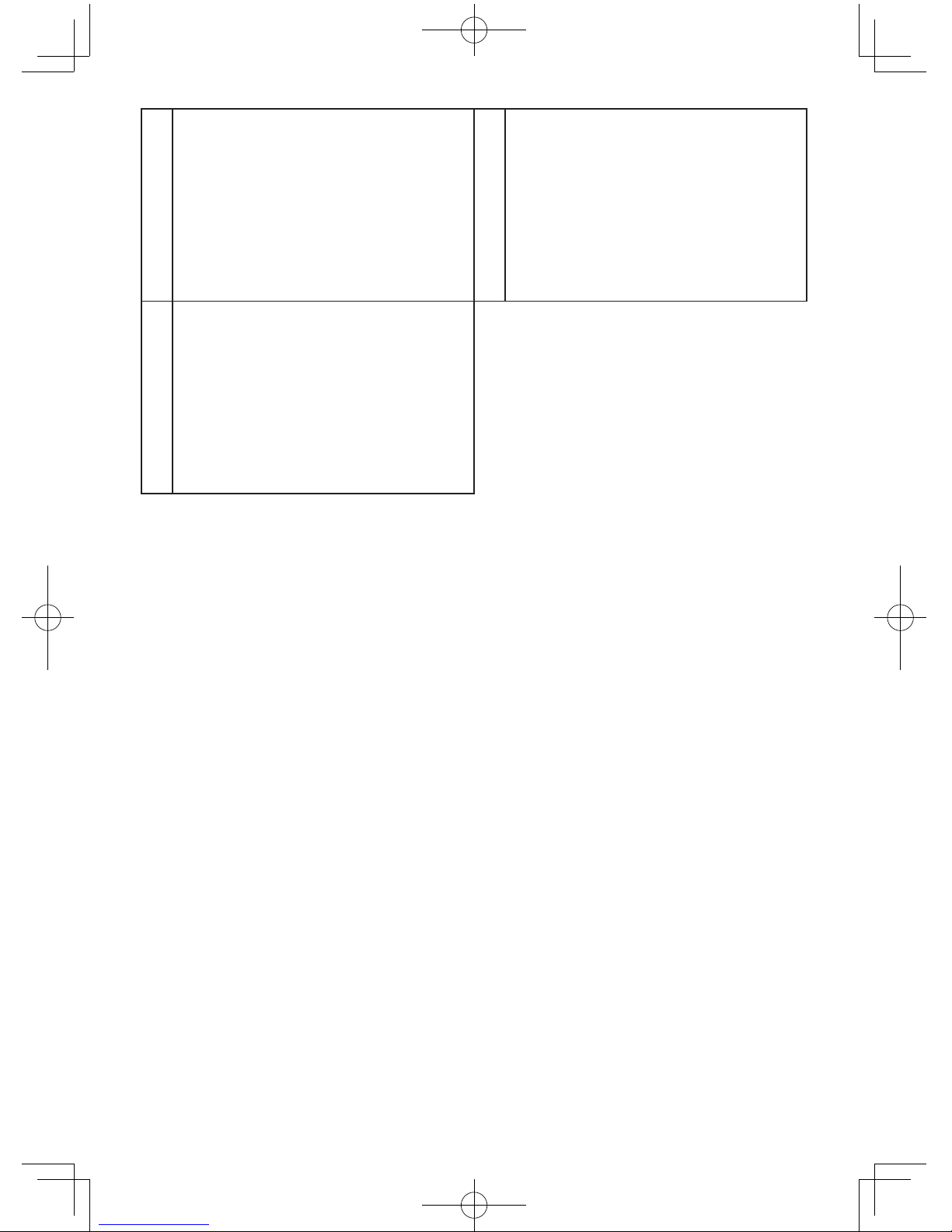
1) Check lower guard for proper closing
before each use. Do not operate the saw
if lower guard does not move freely and
close instantly. Never clamp or tie the lower
guard into the open position.
If saw is accidentally dropped, lower guard
may be bent. Raise the lower guard with the
retracting handle and make sure it moves
freely and does not touch the blade or any
other part, in all angles and depths of cut.
EY45A2(EU).indb 7 2014-1-15 10:13:07

-
8
-
2) Check the operation of the lower guard
spring. If the guard and the spring are not
operating properly, they must be serviced
before use.
Lower guard may operate sluggishly due to
damaged parts, gummy deposits, or a build-
up of debris.
3) Lower guard should be retracted manual-
ly only for special cuts such as “plunge
cuts” and “compound cuts.” Raise lower
guard by retracting handle and as soon
as blade enters the material, the lower
guard must be released.
For all other sawing, the lower guard should
operate automatically.
4) Always observe that the lower guard is
covering the blade before placing saw
down on bench or floor.
An unprotected, coasting blade will cause
the saw to walk backwards, cutting whatever
is in its path. Be aware of the time it takes for
the blade to stop after switch is released.
5) Do not use any abrasive wheels.
6) Wear a dust mask, if the work causes
dust.
7) Use saw blades recommended by Manu-
facture.
8) Wear ear protectors when using the tool for
extended periods.
9) The risk of kickback increases as the bat-
tery pack discharges.
10) Be sure to inspect material. Avoid cutting
other different material.
11) Be careful not to drop the tool.
12) Never swing the tool.
13) Never cover the ventilation slots, and keep
them free from dust or other material.
14) Do not clamp the tool in a vise. Never cut
with the tool held upside down in a vise.
This is extremely dangerous and can lead
to serious accidents.
15) Never wear knitted gloves.
16) Be sure no one is below when using the
tool in high locations.
17) Do not touch the blade immediately after
operation. It may be hot and could burn
your skin.
18) Do not touch material after it has been cut.
Cut material may be very hot.
19) Do not use cutting oil. This use of cutting
oil may cause a fire.
20) Do not cut workpieces covered or stained
with gas, oil, solvents, thinners, etc.
Exposure to these materials may damage
the transparent guard.
21) Do not remove the transparent and lower
guards. If the transparent and lower guards
is damaged or missing, return tool to
authorized service center for replacement.
22) Do not start the blade when in contact
with workpiece. Wait for blade to reach full
speed before beginning cut.
Symbol
Symbol Meaning
VVolts
Direct current
n0No load speed
··· min-1 Revolutions or
reciprocations
AAmperes
To reduce the risk of
injury, user must read and
understand instruction
manual.
For indoor use only.
WARNING
• Do not use other than the Panasonic battery
packs that are designed for use with this
rechargeable tool.
• Panasonic is not responsible for any dam-
age or accident caused by the use of the
recycled battery pack and the counterfeit
battery pack.
• Do not dispose of the battery pack in a fire,
or expose it to excessive heat.
•
Do not drive the likes of nails into the bat-
tery pack, subject it to shocks, dismantle it, or
attempt to modify it.
• Do not allow metal objects to touch the bat-
tery pack terminals.
• Do not carry or store the battery pack in
the same container as nails or similar metal
objects.
•
Do not charge the battery pack in a high-
temperature location, such as next to a fire or
in direct sunlight. Otherwise, the battery may
overheat, catch fire, or explode.
EY45A2(EU).indb 8 2014-1-15 10:13:08

-
9
-
•
Never use other than the dedicated charger
to charge the battery pack. Otherwise, the
battery may leak, overheat, or explode.
•
After removing the battery pack from the
tool or the charger, always reattach the pack
cover. Otherwise, the battery contacts could
be shorted, leading to a risk of fire.
•
When the Battery Pack Has Deteriorated,
Replace It with a New One.
Continued use of a damaged battery pack
may result in heat generation, ignition or bat-
tery rupture.
III
. ASSEMBLY
Attaching or Removing Battery
Pack
CAUTION:
Before inserting battery pack, check that the
power switch in the tool actuates properly and
returns to the “OFF” position when released.
1. To connect the battery pack (See Fig. 2)
Align the highlighted marker points and attach
battery pack.
• Slide the battery pack until it locks into posi-
tion.
Alignment
marks
Fig. 2
2. To remove the battery pack (See Fig. 3)
Push down the button and slide the battery
pack forward.
Button
Fig. 3
IV
. OPERATION
Before Using the Tool
This tool is intended to cut unhardened fer rous
metal, nonferrous metal, wood, and plastic.
Refer to the “Accessories” section for a list of
blades to be used for the proper applications
of this tool. The following precautions must be
followed to reduce the risk of injury;
• Do not cut stacked materials. Cut one piece at
a time.
• Do not cut hardened steel.
• Cut materials with the wider edge of the shoe
over the clamped side of the material.
• Do not touch the saw blade, workpiece, or cut-
ting chips with bare hands immediately after
cutting; they may be hot and could burn skin.
Each time you use the tool, you must make sure
it is in good operating condition.
Use the following checklist:
1. Is the blade installed in the correct direction?
The arrow on the blade must point in the same
direction as the arrow on the upper blade
cover.
2. Is the blade installed properly?
Make sure the hex bolt is tightened securely.
(See Fig. 6)
3. Does the blade look alright?
Replace the blade immediately if there are
any cracks in it or if any teeth are broken.
4. Does the lower guard close properly?
WARNING
To avoid injury, do not use the tool if the lower
guard does not close quickly over the blade.
5. Is the transparent guard securely installed?
6. Is the battery pack charged and inserted
firmly to the tool?
7. Is the depth adjustment nut for cutting secure-
ly tightened?
8. Is the workpiece securely clamped on a saw
horse or bench?
9. Is the dust case or front cover clogged with
dust?
10. Only use the blade rated at higher speed
than that of main unit.
The blade may be damaged if the blade is
used under the rated speed of the main unit.
Disengage the front cover lock button and
remove any dust that has become clogged in-
side the cover. If the cover is clogged, use a long
object such as a manual screwdriver to unclog it.
After doing so, close the front cover. (See Fig. 4)
EY45A2(EU).indb 9 2014-1-15 10:13:08

-
10
-
Front cover Lock button
Fig. 4
If there is dust inside the dust case, disengage
the dust case lock button, detach the dust case,
and remove the dust. After doing so, reattach the
dust case. (See Fig. 5)
Dust case
Lock button
Fig. 5
Installing Blade
Follow these steps:
1. Remove the battery pack from the tool.
2. Remove any cutting debris from blade area.
3. Use the retracting handle to retract (open)
the lower guard.
4. Install the blade as illustrated. (See Fig. 6)
Make sure that both the direction arrow on
the blade and the direction arrow on the
transparent guard point in the same direc-
tion.
5. Set the outer washer in place.
6. Insert the hex bolt.
7. Hold the spindle lock button down. This pre-
vents the blade from rotating.
8. Tighten the hex bolt securely with the provid-
ed hex wrench. Store the hex wrench.
NOTE:
Keep the hex wrench in the storage slot on
the tool’s body when not using it.
WARNING
Failure to follow these instructions can result in
serious personal injury.
Removing Blade
CAUTION:
The blade will be hot right after cutting. Be sure
to let the blade cool down before removing it.
Follow these steps:
1. Remove the battery pack from the tool.
2. Hold the spindle lock button down. This pre-
vents the blade from rotating.
3. Use the provided hex wrench to loosen the
hex bolt.
NOTE:
Keep the hex wrench in the storage slot on
the tool’s body when not using it.
4. Remove the hex bolt and outer washer.
5. Use the retracting handle to retract (open)
the lower guard.
6. Carefully remove the blade.
7. Clean the tool if necessary.
CAUTION:
Be careful to avoid cutting your hands on the
blade.
• When disposing of a blade, secure it inside heavy
or corrugated paper. This will help prevent anyone
from being cut by the discarded blade.
EY45A2(EU).indb 10 2014-1-15 10:13:08

-
11
-
Retracting handle
Hex bolt
Loosen
Tighten
Outer washer
Place the protrusion of the outer
washer into the position of the
washer.
Lower guard
Inner washer
Place the inner washer with cut-out
facing you.
Spindle lock button
Fig. 6
Using the Tool
CAUTION:
To reduce the risk of injury read the Safety
In structions at the front of this manual before
using the tool.
WARNING
To reduce the risk of injury, wear safety gog-
gles or glasses with side shields while using the
tool. Additionally, wear a dust mask when cutting
materials that generate excessive particulate
matter. Do not use tool in the rain. Doing so may
result in electric shock or cause the tool to emit
smoke.
Do not cut materials on which there is any
paint thinner, gasoline, oil, or similar build-up.
Doing so may cause the dust case to crack,
resulting in injury.
Follow these steps:
Hold the tool with both hands. (See Fig. 8) Do
not attempt to remove cut material when blade
is moving.
1. Line up the sight line on shoe with your cut-
ting line. (See Fig. 7)
Alignment with cutting line
• Position the notch on the shoe over the cutting
line, aligning the top and bottom corners of the
diamond-shaped opening with the line.
As the cutting position may differ depending on
the blade, do a trial cut beforehand.
Cutting line
Notch
Fig. 7
2. Press the switch lock lever down, then
squeeze the power switch to start the motor,
and then release the switch lock lever.
EY45A2(EU).indb 11 2014-1-15 10:13:09

-
12
-
Switch lock lever
Front grip
Handle
Power switch
Fig. 8
CAUTION:
• Check that the switch lock lever works.
If power switch can be activated without
depressing the switch lock lever, discontinue
use immediately. Take the tool to an authorized
service center.
• Always hold the handle with one hand and the
front grip with the other. (See Fig. 8) Maintain a
firm grip and depress the switch fully.
• The blade should not touch the cutting material
before you start the motor. Wait until the blade
reaches full speed before starting a cut.
• This tool has no provision to lock the power
switch in the “ON” position, and you must not
attempt to secure it in the “ON” position.
3. Start cutting when the blade reaches full
speed.
CAUTION:
• To prevent reaction when starting operation,
the blade starts at reduced speed. (Soft start)
4. During cutting, keep your cutting line straight.
Move the tool forward at a steady speed,
while looking at the tip of the blade through
the transparent guard.
WARNING
• To prevent dangerous kickback, keep the
shoe of the tool flat on the surface of the
material being cut.
• Never force the tool. Use light and continuous
pressure.
5. If the motor become too warm, stop cutting.
Let the tool cool down before continuing work.
6. It is always a safe practice to remove the bat-
tery pack after use and before storing the tool.
Cutting depth adjustment
• Remove battery pack.
• Loosen the depth adjustment nut and adjust
the cutting depth, using the graduations on the
lower guard to gauge the depth. Once finished
adjusting the depth, tighten the depth adjust-
ment nut securely.
* When wood material is 10 mm (3/8”) or less
thick, adjust the cutting depth so that the blade
protrudes approx. 5 mm (3/16”) from the bottom
of the material.
Depth
adjustment
nut
Pull down
Loosen
Tighten
Fig. 9
Rip fence (EY3500B7727)
(Available as an accessory, not included)
Rip fence is convenient for rip cuts and repeated
cuts of uniform width.
• Remove battery pack.
• Insert rip fence and adjust cutting width. (See
Fig. 10)
• Fasten screw securely to fix rip fence.
Insert and
adjust
Fasten screw
Rip fence
Fig. 10
EY45A2(EU).indb 12 2014-1-15 10:13:09

-
13
-
Collecting Dust
WARNING
* Before cutting metal materials, always empty
the dust case, open the front cover and
remove the dust.
• Use the tool with the flammable materials
in the dust case to cut metal materials may
result in fire.
*
When cutting metal materials, always use the
tool with the dust case attached.
• Flying sparks and metal chips may cause
injury.
* When cutting metal materials, do not attach
a vacuum cleaner.
Sparks and hot metal chips may cause
the vacuum to be caught in fire. Operate
the vacuum cleaner in accordance with its
instructions.
(1) Collect dust in the dust case.
* Empty the dust case when it is filled up with
dust.
* Empty the dust case before storing the tool.
* Dust case capacity
• When cutting electrical conduit with a
diameter of 25 mm (1”), approximately
130 cuts
• When cutting 45 mm (1-25/32”) x 45 mm
(1-25/32”) lumber, approximately 150 cuts
NOTE:
Some materials may cause dust to become
clogged inside the front cover when cutting
those materials.
Front cover
Fig. 11
(2) Use with vacuum cleaner to collect dust.
* Connect the tool to the hose using the
EY9X012E vacuum cleaner hose adapter
(sold separately).
Compatible hose inner diameter: 25 mm
(1”) to 38 mm (1-2/1”)
* Operate the vacuum cleaner obeying its
instructions.
Fig. 12
NOTE:
When the tool has difficulty in ejecting or col-
lecting dust, the dust outlet may be clogged
with dust. Open the front cover and remove
any dust.
LED light
LED light
Fig. 13
LED light illuminates when the power switch is
depressed and turns off when the power switch
is released.
• The light illuminates with very low current, and it
does not adversely affect the performance of the
tool during use or its battery capacity.
CAUTION:
• The built-in LED light is designed to illuminate the
small work area temporarily.
• Do not use it as a substitute for a regular flashlight,
since it does not have enough brightness.
Caution : DO NOT STARE INTO BEAM.
Use of controls or adjustments or performance
of procedures other than those specied herein
may result in hazardous radiation exposure.
EY45A2(EU).indb 13 2014-1-15 10:13:10

-
14
-
Control Panel
(1) (2)
(1) Overheat warning lamp
Off
(normal
operation)
Flashing: Overheat
Indicates operation has
been halted due to battery
overheating.
The overheating protection feature halts tool
operation to protect the battery pack in the event
of overheating. The overheat warning lamp on the
control panel flashes when this feature is active.
• If the overheating protection feature activates,
allow the tool to cool thoroughly (at least 30
minutes). The tool is ready for use when the
overheat warning lamp goes out.
• Avoid using the tool in a way that causes the
overheating protection feature to activate
repeatedly.
• If the tool is used in cold-temperature condi-
tions (such as during winter) or if it is frequently
stopped during use, the overheating protection
feature may not activate.
The performance of the EY9L42 de-teriorates
significantly at and below 10 °C due to work
conditions and other factors.
• The ambient temperature range is between
0 °C (32 °F) and 40 °C (104 °F).
If the battery pack is used when the battery
temperature is below 0 °C (32 °F), the tool may
fail to function properly.
• When charging a cool battery pack (below 0 °C
(32 °F)) in a warm place, leave the battery
pack at the place and wait for more than one
hour to warm up the battery to the level of the
ambient temperature.
(2) Battery low warning lamp
Off
(normal
operation)
Flashing
(No charge)
Battery protection
feature active
Excessive (complete) discharging of lithium ion
batteries shortens their service life dramatically.
The tool includes a battery protection feature
designed to prevent excessive discharging of
the battery pack.
• The battery protection feature activates imme-
diately before the battery loses its charge,
causing the battery low warning lamp to flash.
• If you notice the battery low warning lamp
flashing, charge the battery pack immediately.
• If it is started with too little battery power
remaining, the tool may stop operating without
the battery low warning lamp flashing first. This
indicates that there is too little battery power
remaining to use the tool, and the battery pack
should be charged before further use.
• If the tool is subject to a sudden load during
use that causes the motor to lock up, the over-
discharge prevention sensor may be triggered,
and the battery low warning lamp may flash.
The lamp will stop flashing once you address
the cause of the motor’s locking up and cycle
the trigger.
CAUTION:
The over-discharge protection function works
even when both the battery low warning lamp
and LED light are flashing.
• Charge the battery pack immediately as the
battery power is getting low.
• When charging a cool battery pack (below
0 °C (32 °F)) in a warm place, leave the battery
pack at the place and wait for more than one
hour to warm up the battery to the level of the
ambient temperature.
• Weaken and cut off the power applied as the
voltage of the battery is plummeting due to the
high load acting on the motor. Do not carry out
operations that will repeatedly cause the over-
discharge prevention function to be activated.
EY45A2(EU).indb 14 2014-1-15 10:13:10

-
15
-
Fig. 14
Fig. 15
Fig. 16
For Proper Use (Further Detail)
WARNING
To prevent the risk of serious personal injury:
l It is important to use an appropriate device
to hold the material being cut properly, and
to hold the tool firmly with both hands to
prevent loss of control which could cause
personal injury.
• Figure 14 shows proper cutting position.
• Note that hands are kept away from cutting
area.
• Make sure bystanders are away from work
area and from underneath of workpiece.
• When cutting, do not try to hold the mate-
rial with your hand.
Cutting large sheets;
Support large sheets. Be sure to set the depth
of the cut so that you only cut through the
workpiece, not through the supports. (See
Fig. 15)
Large sheets sag or bend if they are not cor-
rectly supported. If you attempt to cut without
levelling and properly supporting the work-
piece, the blade will tend to bind, causing
kickback. (See Fig. 16)
• Don’t support the material away from the cut.
Cutting thin or corrugated materials;
Cut thin and corrugated materials at least 25
mm (1") from the edge of the workpiece to
avoid injury or damage to the tool caused by
thin strips of metal being pulled into the upper
guard.
• Use sharp blades only. Clean and sharp
blades minimize stalling and kickback.
EY45A2(EU).indb 15 2014-1-15 10:13:11

-
16
-
WARNING
To prevent the risk of serious personal injury:
• When making an incomplete cut or cutting is interrupted, or blade is binding or tool is stalling; release the
power switch immediately and hold the tool motionless in the material until the blade comes to a complete
stop.
• To avoid kickback, never attempt to remove the tool from the work or pull the tool backward while the blade is
in motion. Make sure the blade has come to a complete stop, then remove tool from cut.
• To resume cutting, start tool, allow the blade to reach full speed, reenter the cut slowly and resume cutting.
1. Place the wider part of the shoe on the part of the work piece which is solidly supported (See Fig.
17), never on the section that will fall off when the cut is made. (See Fig. 18)
Hold the tool firmly to prevent loss of control. Working carelessly can cause severe personal injury.
Fig. 17 Fig. 18
2. Make sure the blade stops.
Even though your tool has a brake, before setting the tool down, make sure the blade has come to
a complete stop and the lower guard has closed.
3. Do not use if anything seem unusual. Remove battery pack immediately.
If the tool body becomes very hot, or does not work properly, remove the battery pack and do not
use. Have it checked by an authorized service center.
WARNING
To prevent the risk of serious personal injury or fire, do not try to repair the tool by yourself. Never
disassemble or modify the tool body. There are no user-repairable parts inside.
4. NEVER ALLOW THE TOOL TO COME IN CONTACT WITH YOUR BODY.
After completing a cut, do not allow the tool to brush against your leg or side.
Since the lower guard is retractable, it could catch on your clothing and expose the blade. Keep
clothing away from tool. Be aware of the exposed blade sections that exist in both the upper and
lower guard areas.
WARNING
Because cutting metal creates sparks;
• Always use safety goggles.
• Do not use tool near any flammable substance or in an area where flammable substances are
used. Fire and burn injury could result.
5. Never engage the spindle lock while blade is running, or engage in an effort to stop the tool. Never
turn the switch on when the spindle lock is engaged. Serious damage to your tool will result.
EY45A2(EU).indb 16 2014-1-15 10:13:11

-
17
-
[Battery Pack]
For Appropriate Use of
Bat tery Pack
Li-ion Battery Pack
• For optimum battery life, store the Li-ion bat-
tery pack following use without charging it.
• When charging the battery pack, confirm
that the terminals on the battery charger
are free of foreign substances such as dust
and water etc. Clean the terminals before
charging the battery pack if any foreign sub-
stances are found on the terminals.
The life of the battery pack terminals may be
affected by foreign substances such as dust
and water etc. during operation.
• When battery pack is not in use, keep it away
from other metal objects like: paper clips,
coins, keys, nails, screws, or other small metal
objects that can make a connection from one
terminal to another.
Shorting the battery terminals together may
cause sparks, burns or a fire.
• When operating the battery pack, make sure
the work place is well ventilated.
• When the battery pack is removed from the
main body of the tool, replace the battery
pack cover immediately in order to prevent
dust or dirt from contaminating the battery ter-
minals and causing a short circuit.
Battery Pack Life
The rechargeable batteries have a limited life. If
the operation time becomes extremely short after
recharging, replace the battery pack with a new
one.
Battery Recycling
ATTENTION:
For environmental protection and recycling of
materials, be sure that it is disposed of at an
officially assigned location, if there is one in your
country.
Recommendations for use
Pack cover
Terminals
Label
Be sure to use the Pack cover
• When the battery pack is not being used, store
the battery in a way that foreign substances
such as dust and water etc. do not contami-
nate the terminals. Be sure to attach the bat-
tery pack cover to protect the battery terminals.
• When charging the battery pack, confirm that
the terminals on the battery charger are free of
foreign substances such as dust and water etc.
Clean the terminals before charging the battery
pack if any foreign substances are found on
the terminals.
The life of the battery pack terminals may be
affected by foreign substances such as dust
and water etc. during operation.
CAUTION:
To protect the motor or battery, be sure to note
the following when carrying out operation.
• If the battery becomes hot, the protection func-
tion will be activated and the battery will stop
operating.
The overheat warning lamp on the control
panel illuminates or flashes when this feature
is active.
For safe use
• The battery pack is designed to be installed by
proceeding two steps for safety. Make sure the
battery pack is installed properly to the main
unit before use.
• If the battery pack is not connected firmly when
the switch is switched on, the overheat warn-
ing lamp and the battery low warning lamp will
flash to indicate that safe operation is not pos-
sible, and the main unit will not rotate normal-
ly. Connect the battery pack into the unit of the
tool until the red or yellow label disappears.
EY45A2(EU).indb 17 2014-1-15 10:13:12

-
18
-
Alignment marks
3. During charging, the charging lamp will be
Illuminated.
When charging is completed, an internal elec-
tronic switch will automatically be triggered to
prevent overcharging.
• Charging will not start if the battery pack
is warm (for example, immediately after
heavy-duty operation).
The orange standby lamp will be flashing
until the battery cools down.
Charging will then begin automatically.
4. The charge lamp (green) will flash slowly
once the battery is approximately 80%
charged.
5. When charging is completed, the charging
lamp in green color will turn off.
6. If the temperature of the battery pack is 0 °C
or less, charging takes longer to fully charge
the battery pack than the standard charging
time.
Even when the battery is fully charged, it will
have approximately 50% of the power of a
fully charged battery at normal operating tem-
perature.
7. Consult an authorized dealer if the charging
lamp (green) does not turn off.
8. If a fully charged battery pack is inserted into
the charger again, the charging lamp lights
up. After several minutes, the charging lamp
in green color will turn off.
[Battery Charger]
Charging
CAUTION:
• The charger is designed to operate on
standard domestic electrical power only as
stated in the rating plate. Charge only on the
voltage indicated on the rating plate of unit.
e.g.230V / 50Hz.
• Do not attempt to use it on any other voltage
or frequency rating!
• If the temperature of the battery pack falls
approximately below −10 °C (14 °F), charging
will automatically stop to prevent degradation
of the battery.
• Do not charge the battery pack whose tem-
perature is below 0 °C (32 °F).
• When charging a cool battery pack (below
0 °C (32 °F)) in a warm place, leave the bat-
tery pack at the place and wait for more than
one hour to warm up the battery to the level
of the ambient temperature.
Otherwise battery pack may not be fully
charged.
•
Cool down the charger when charging more
than two battery packs consecutively.
• Do not insert your fingers into contact hole,
when holding charger or any other occasions.
CAUTION:
To prevent the risk of fire or damage to the bat-
tery charger.
• Do not cover vent holes on the charger and
the battery pack.
• Unplug the charger when not in use.
NOTE:
Your battery pack is not fully charged at the
time of purchase. Be sure to charge the
battery before use.
How to charge
1. Plug the charger into the AC outlet.
NOTE:
Sparks may be produced when the plug is
inserted into the AC power supply, but this is
not a problem in terms of safety.
2.
Connect the battery pack firmly into the charger.
1
Line up the alignment marks and place the
battery onto the dock on the charger.
2
Slide forward in the direction of the arrow.
EY45A2(EU).indb 18 2014-1-15 10:13:12

-
19
-
Lamp Indications
Charging is completed. (Full charge.)
Battery is approximately 80% charged.
Now charging
Charger is plugged into the AC outlet.
Ready to charge.
(Green) (Orange)
Charging Status Lamp
Left: green Right: orange will be displayed.
Battery pack is cool.
The battery pack is being charged slowly to reduce the load on the
battery.
Battery pack is warm.
Charging will begin when temperature of battery pack drops. If the
temperature of the battery pack is -10 °C or less, the charging sta-
tus lamp (orange) will also start ashing. Charging will begin when
the temperature of the battery pack goes up.
Charging is not possible. Clogged with dust or malfunction of the
battery pack.
Turn off Illuminated Flashing
Information for Users on Collection and Disposal of Old Equip-
ment and used Batteries
These symbols on the products, packaging, and/or accompanying documents mean that
used electrical and electronic products and batteries should not be mixed with general
household waste.
For proper treatment, recovery and recycling of old products and used batteries, please
take them to applicable collection points, in accordance with your national legislation and
the Directives 2002/96/EC and 2006/66/EC.
By disposing of these products and batteries correctly, you will help to save valuable
resources and prevent any potential negative effects on human health and the
environment which could otherwise arise from inappropriate waste handling.
For more information about collection and recycling of old products and batteries, please
contact your local municipality, your waste disposal service or the point of sale where you
purchased the items.
Penalties may be applicable for incorrect disposal of this waste, in accordance with
national legislation.
For business users in the European Union
If you wish to discard electrical and electronic equipment, please contact your dealer or supplier for
further information.
[Information on Disposal in other Countries outside the Euro-
pean Union]
These symbols are only valid in the European Union. If you wish to discard these items, please con-
tact your local authorities or dealer and ask for the correct method of disposal.
EY45A2(EU).indb 19 2014-1-15 10:13:13

-
20
-
V
. MAINTENANCE
WARNING
To avoid severe personal injury, always remove
the battery pack from the tool before starting any
maintenance procedure.
CAUTION:
To assure product SAFETY and RELIABILITY,
servicing should be performed by an autho-
rized service center. Always insist on genuine
Panasonic replacement parts.
Cleaning Tool
Keep your tool clean for good cutting perform-
ance, and to help keep it safe to use.
Follow these steps:
1. Remove the battery pack from the tool.
2. Wipe the tool with a dry, soft cloth. Do not
use a wet cloth or cleaning liquids.
They could damage the tool’s finish.
3. Be sure to rub off any oil or grease which
could make the tool slippery or hard to handle.
4. Remove the blade and brush off any dust.
CAUTION:
• To avoid injury or damage to the unit, never
immerse any part of the tool in a liquid.
• In the event that the inside of the tool or bat-
tery pack is exposed to water, drain and allow
to dry as soon as possible. Carefully remove
any dust or iron filings that collect inside the
tool. If you experience any problems operating
the tool, consult with a repair shop.
Transparent Guard
WARNING
If the guard is cracked, or is broken, take the tool
to an authorized service center for replacement.
Do not attempt to operate tool. It could result in
serious personal injury.
Never use your tool with a damaged transparent
guard or without the transparent guard installed.
Flying chips could result in serious injury.
VI
. ACCESSORIES
WARNING
• The use of any accessories not specified
in this manual may result in fire, electric
shock, or personal injury. Use recommended
accessories only.
• Use of a blade on material that is thicker
or thinner than that recommended for that
blade will result in a rough cut, and could
increase the risk of “kickback” or other injury.
Carbide-tipped Blade for Metal
• EY9PM13E
For cutting unhardened ferrous material
Thickness of material
0.5 mm – 6.0 mm
Carbide-tipped Blade for Thin Metal (Optional
accessory)
• EY9PM13F
For cutting unhardened thin ferrous thin material
that clean cutting edge required
Thickness of material
0.5 mm – 6.0 mm
Carbide-tipped Blade for Wood (Optional
accessory)
• EY9PW13C
For cutting wood in general
Carbide-tipped Blade for Thin Wood (Optional
accessory)
• EY9PW13D
For cutting thin wood that clean cutting edge
required
Recommended thickness of material up to 12
mm
Carbide-tipped Blade for Plastic (Optional
accessory)
• EY9PP13C
For cutting plastic
Recommended thickness of material acrylic
and vinyl chloride plates:
2.0 mm – 5.0 mm
corrugated pates, pipes
0.8 mm – 5.0 mm
Vacuum hose adaptor (Optional accessory)
• EY9X012E
Rip Fence (Optional accessory)
• EY3500B7727
For convenience of rip cuts and repeated cut of
uniform width
EY45A2(EU).indb 20 2014-1-15 10:13:13
Other manuals for EY45A2
1
Table of contents
Languages:
Other Panasonic Cutter manuals

Panasonic
Panasonic EY3552 - 18V METAL SAW User manual

Panasonic
Panasonic EY3550 User manual

Panasonic
Panasonic EY3502 - CORDLESS METAL SAW User manual

Panasonic
Panasonic EY45A2LJ2G User manual

Panasonic
Panasonic EY3530NQMKW User manual

Panasonic
Panasonic EY4542XM User manual

Panasonic
Panasonic EY3552 - 18V METAL SAW User manual

Panasonic
Panasonic EY4542LN2M User manual

Panasonic
Panasonic EY3502 - CORDLESS METAL SAW User manual

Panasonic
Panasonic EY45A2 User manual