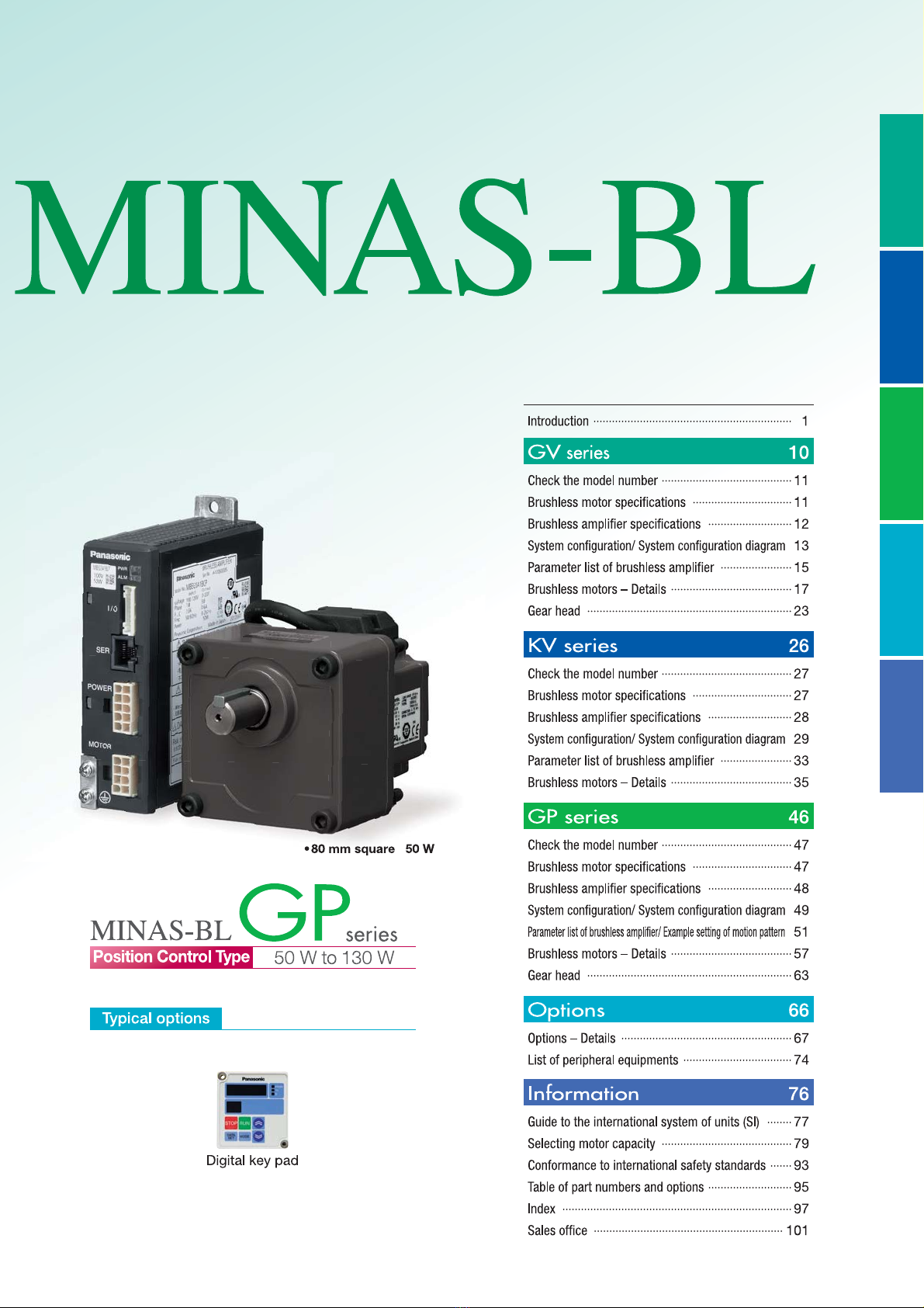
Panasonic MINAS-BL GV series User manual


KVseriesGVseries Options Information
GPseries


6


9


PPVTXDUH:
Contents
&KHFNWKHPRGHOQXPEHU
%UXVKOHVVPRWRUVSHFLILFDWLRQV
%UXVKOHVVDPSOLILHUVSHFLILFDWLRQV
6\VWHPFRQILJXUDWLRQ6\VWHPFRQILJXUDWLRQGLDJUDP
3DUDPHWHUOLVWRIEUXVKOHVVDPSOLILHU
%UXVKOHVVPRWRUV²'HWDLOV
KVseriesGVseries Options Information
GPseries

9
Brushless motor specifications
Item Specifications
'MBOHFTJ[F NNTR 6NNTR NNTR
.PUPSNPEFM/P *1
MBMS5AZBL
○
MBMS011BL
○
MBMS012BL
○
MBMS021BL
○
MBMS022BL
○
MBMS042BL
○
MBMS082BL
○
.PUPS SBUFE PVUQVU
8 1
7PMUBHF 7 GPS 1 GPS 1 GPS GPS 1 GPS GPS
3BUFE UPSRVF
/・N 16 61
4UBSUJOH UPSRVF*
/・N 1
3BUFE JOQVU DVSSFOU
"SNT 1 91 6
.PNFOU PG JOFSUJB PG
SPUPS ¨1¦ Lg・N 1 6
3BUJOH $POUJOVPVT
3BUFE SPUBUJPO TQFFE
*
SNJO
4QFFE DPOUSPM SBOHF
SNJO 1 UP
"NCJFOU UFNQFSBUVSF
UP + GSFF GSPN GSFF[JOH
* "NCJFOU UFNQFSBUVSF JT NFBTVSFE BU BEJTUBODF PG DN GSPN UIF NPUPS
"NCJFOU IVNJEJUZ UP 3) GSFF GSPN DPOEFOTBUJPO
"MUJUVEF -PXFS UIBO 1 N
7JCSBUJPO NTPS MFTT 9:; $FOUFS PG GSBNF
.PUPS JOTVMBUJPO DMBTT
1#
1SPUFDUJPO TUSVDUVSF *16**
/VNCFS PG QPMFT
.PUPS NBTT Lg 6 1
*1 4VGmY PG i○wJO UIF NPUPS NPEFM SFQSFTFOUT TIBQF PG TIBGU
*3FQSFTFOUBUJWF WBMVF
*.PUPS TIBGU TQFFE UP CF NVMUJQMJFE CZ UIF SFEVDUJPO SBUJP XIFO UIF HFBS IFBE JT VTFE
*&YDMVEJOH UIF TIBGU QBTTUISPVHI TFDUJPO BOE DBCMF FOE DPOOFDUPS
*5IFTF NPUPST DPOGPSN UP UIF UFTU DPOEJUJPOT TQFDJmFE JO &/ TUBOEBSET &/69&/6
%P OPU VTF UIFTF NPUPST JO BQQMJDBUJPO XIFSF XBUFS QSPPG QFSGPSNBODF JT SFRVJSFE TVDI BT DPOUJOVPVT XBTIEPXO PQFSBUJPO
Check the model number
<Motor> MBMS08 2BL ○
●Rated rotation speed
B: 3000 r/min
●Mounting method
L : Flange type
●Motor rated output
5A : 50 W
01 : 100 W
02 : 200 W
04 : 400 W
08 : 750 W
Type
●Motor specifications
〇: Refer to the table below.
●Input power supply
1 : 100 V
2 : 200 V
Z: 100 V/200 V
Oil seal without
with
A
C
Shaft
S
U
N
Q
Round D-cut
Keyway,
center tap

Brushless amplifier specifications (KV series)
Item Specifications
"NQMJGJFS NPEFM /P
MBEK5A1BCV MBEK5A5BCV MBEK011BCV MBEK015BCV MBEK021BCV MBEK025BCV MBEK043BCV MBEK083BCV
"QQMJDBCMF .PUPS *1
MBMS5AZBL
○
MBMS011BL
○
MBMS012BL
○
MBMS021BL
○
MBMS022BL
○
MBMS042BL
○
MBMS082BL
○
.PUPS SBUFE PVUQVU 8
1
*OQVU QPXFS TVQQMZ WPMUBHF
7
4JOHMF QIBTF
1 UP 1
4JOHMF
QIBTF
QIBTF
4JOHMF QIBTF
1 UP 1
4JOHMF
QIBTF
QIBTF
4JOHMF QIBTF
1 UP 1
4JOHMF
QIBTF
QIBTF
QIBTF
UP
UP UP UP
'SFRVFODZ )[ 6
3BUFE JOQVU DVSSFOU "
1 9 1 11 1
7PMUBHF UPMFSBODF ±1%
$POUSPM NFUIPE 4QFFE DPOUSPM CZ $4 TJHOBM 18. TJOF XBWF ESJWJOH TZTUFN
"NCJFOU UFNQFSBUVSF UP + GSFF GSPN GSFF[JOH
* "NCJFOU UFNQFSBUVSF JT NFBTVSFE BU BEJTUBODF PG DN GSPN UIF BNQMJGJFS
"NCJFOU IVNJEJUZ UP 3) GSFF GSPN DPOEFOTBUJPO
-PDBUJPO *OEPPS /P DPSSPTJWF HBT "QMBDF XJUIPVU HBSCBHF BOE EVTU
"MUJUVEF -PXFS UIBO 1 N
7JCSBUJPO 9 NTPS MFTT 1)[ UP 6)[
1SPUFDUJPO TUSVDUVSF $PPMJOH TZTUFN
&RVJWBMFOU UP *1 4FMG DPPMJOH
4UPSBHF UFNQFSBUVSF /PSNBM UFNQFSBUVSF
* 5FNQFSBUVSF XIJDI JT BDDFQUBCMF GPS BTIPSU UJNF TVDI BT EVSJOH USBOTQPSUBUJPO JT o UP 6 GSFF GSPN GSFF[JOH
4UPSBHF IVNJEJUZ /PSNBM IVNJEJUZ
3BUFE SPUBUJPO TQFFE SNJO
4QFFE DPOUSPM SBOHF 1 SNJO UP SNJO
4QFFE
GMVDUVBUJPO
GBDUPS
8JUI MPBE ± PS CFMPX BU UP 3BUFE UPSRVF 3BUFE SPUBUJPO TQFFE
8JUI WPMUBHF ± PS CFMPX BU TVQQMZ WPMUBHF ±1 SBUFE SPUBUJPO TQFFE
8JUI UFNQFSBUVSF
± PS CFMPX BU ¡$ UP ¡$ SBUFE SPUBUJPO TQFFE
"DDFMFSBUJPO %FDFMFSBUJPO UJNF
1 TFD UP TFD UJNF GPS DIBOHJOH 1 SNJO*
4UPQQJOH QSPDFEVSF 4MPXEPXO TUPQ 'SFFSVO TUPQ*
4QFFE TFUUJOH SNJO UP SNJO BOBMPHVF WPMUBHF 7UP 7 DPOTPMF "
SNJO UP SNJO 4FUUJOH TFMFDUJPO CZ QBSBNFUFS PO %JHJUBM LFZ QBE
4QFFE TFUUJOH SFTPMVUJPO "OBMPH BQQSPY 1 PG VQQFS TQFFE MJNJU %JHJUBM 1 SNJO
4QFFE TFUUJOH QSFDJTJPO
BU ¡$
"OBMPHVF ±PS CFMPX PG VQQFS TQFFE MJNJU ±9SNJO PS CFMPX BU VQQFS TQFFE MJNJU SNJO
<%JHJUBM 1 PS CFMPX PG VQQFS TQFFE MJNJU >
0QFSBUJPO NPEF TQFFE
4JHOBM JOQVU JOQVUT*SVO TUPQ $8 SVO $$8 SVO NVMUJ GVODUJPO CJU
4JHOBM PVUQVU PVUQVUT 0QFO DPMMFDUPS*5SJQ PVUQVU FUD
$PNNVOJDBUJPO
GVODUJPO
34 .BY 1 VOJUT 4FUUJOH PG QBSBNFUFS NPOJUPSJOH PG DPOUSPM DPOEJUJPO
$PNNVOJDBUJPO TQFFE $IPPTF GSPN CQT CQT 96 CQT
34 4FUUJOH PG QBSBNFUFS BOE NPOJUPSJOH PG DPOUSPM DPOEJUJPO BSF FOBCMFE XJUI DPNNFSDJBM 1$*
%JHJUBM LFZ QBE 4FUUJOH PG QBSBNFUFS NPOJUPSJOH PG DPOUSPM DPOEJUJPO*
1SPUFDUJWF GVODUJPO
8BSOJOH 6OEFSWPMUBHF*0WFSMPBE XBSOJOH TFUUJOH DIBOHF XBSOJOH
1SPUFDU 6OEFSWPMUBHF*0WFSMPBE 0WFSDVSSFOU 0WFSWPMUBHF 0WFSIFBU 0WFSTQFFE 4FOTPS FSSPS
34 DPNNVOJDBUJPO FSSPS &YUFSOBM GPSDFE USJQ FSSPS 6TFS QBSBNFUFS FSSPS $16 FSSPS
3FHFOFSBUJOH CSBLF
3FHFOFSBUJWF CSBLJOH SFTJTUPS DBO CF FYUFSOBMMZ DPOOFDUFE*
*OTUBOUBOFPVT CSBLJOH UPSRVF 1 $POUJOVPVT SFHFOFSBUJWF QPXFS 18
3FHFOFSBUJWF PQFSBUJPO XJUI XIJDI NPUPS TIBGU JT SPUBUFE CZ MPBE FH MPBE MPXFSJOH PQFSBUJPO TIPVME OPU CF DPOUJOVFE
1SPUFDUJPO MFWFM 0WFSMPBE QSPUFDUJPO 11 5JNF DIBSBDUFSJTUJDT 1 6TFD
"NQMJGJFS NBTT Lg 8 1 8 1 8UP 8
*1 4VGmY PG i○wJO UIF NPUPS NPEFM SFQSFTFOUT TIBQF PG TIBGU *$BO CF DIBOHFE GSPN 1"/"5&3. GPS #- PS %JHJUBM LFZ QBE
*1"/"5&3. GPS #- %PXOMPBE GSPN PVS XFC TJUF 1$ DPOOFDUJPO DBCMF %711 %JHJUBM LFZ QBE DPOOFDUJPO DBCMF %71*
JT SFRVJSFE *G ZPVS 1$ EPFT OPU IBWF 34 QPSU VTF 3464# DPOWFSUFS
*%JHJUBM LFZ QBE DPOOFDUJPO DBCMF %71* JT SFRVJSFE *6TF PQUJPOBM FYUFSOBM SFHFOFSBUJWF SFTJTUPS TPME TFQBSBUFMZ
<Brushless amplifier> MBEK083BCV
●Function 1
B: with circuit for regenerative resistor
●Motor rated output
5A: 50 W
01 : 100 W
02 : 200 W
04 : 400 W
08 : 750 W
Type
●Function 2
C: RS485 communication,
Signal input/Sink type (NPN transistor)
D: RS485 communication,
Signal input/Source type
(PNP transistor)
Source type made to order item.
Please contact us if you'd like detailed
information.
●Control mode
V: speed control
●Input power supply
1: Single phase AC100 V to 120 V
3: 3-phase AC200 V to 240 V
5: Single phase/ 3-phase AC200 V to 240 V
KVseriesGVseries Options Information
GPseries

1
System configuration (50 W, 100 W)
Power
supply
Rated
rotation
speed
(r/min)
output
(W)Motor
/PUF 1
Brushless
amplifier
Brushless amplifier
TVQQMJFE XJUI
QPXFS DBCMF
/PUF
Optional parts
External
regenerative
resistor
Noise filter Surge
absorber Reactor
Reference page
Q Q 1Q 6Q6Q
4JOHMF
QIBTF
1 7
MBMS5AZBL○MBEK5A1BCV MBEK5A1BCVC GPS 1 7
DV0P2890
GPS TJOHMF QIBTF
QPXFS TVQQMZ
DV0P4170
GPS TJOHMF QIBTF
QPXFS TVQQMZ
DV0P4190
GPS TJOHMF QIBTF
QPXFS TVQQMZ
DV0P227
1 MBMS011BL○MBEK011BCV MBEK011BCVC
4JOHMF
QIBTF
7
MBMS5AZBL○MBEK5A5BCV MBEK5A5BCVC
GPS 7
DV0PM20068
GPS TJOHMF QIBTF
QPXFS TVQQMZ
DV0P4170
GPS QIBTF
QPXFS TVQQMZ
DV0PM20042
GPS TJOHMF QIBTF
QPXFS TVQQMZ
DV0P4190
GPS QIBTF
QPXFS TVQQMZ
DV0P1450
GPS TJOHMF QIBTF
QPXFS TVQQMZ
DV0P227
GPS QIBTF
QPXFS TVQQMZ
DV0P220
1 MBMS012BL○MBEK015BCV MBEK015BCVC
/PUF 1
〇3FGFS UP UIF UBCMF CFMPX
/PUF 3FGFS UP Q GPS BQPXFS TVQQMZ DPOOFDUJOH DBCMF
5IJT QBSU OVNCFS JT UIF PSEFSJOH QBSU OVNCFS GPS UIF BNQMJmFS BOE QPXFS DBCMF OPU GPS PSEFSJOH BNQMJmFS POMZ
Shaft shape
Round Keyway,
center tap D-cut
0JM TFBM 8JUIPVU ASN
8JUI CUQ
* 8IFO JOTUBMMJOH UIF SFBDUPS SFGFS UP Q
* Be sure to use a set of matched components (power source, capacity, output, etc.)
* This motor is not provided with a holding brake. If it is used to drive a vertical shaft, the movable
section may fall down by its own weight as power is turned off.
■Options
Optional parts Parts number
Reference
page
Optional parts Parts number
Reference
page
.PUPS FYUFOTJPO DBCMF
1 NDV0PQ1000310
1 69
%JHJUBM LFZ QBE
DPOOFDUJPO DBCMF
1 NDV0P38310
1 6
NDV0PQ1000330 NDV0P38330
NDV0PQ1000350 NDV0P38350
1NDV0PQ10003A1 &YUFSOBM TQFFE TFUUFS DV0PM20078 1 1
1PXFS TVQQMZ DPOOFDUPS LJU DV0P2870 1 $POUSPM TJHOBM DBCMF NDV0PM20076 1
$POTPMF "*1 DV0P3500 1 6*0 DPOOFDUPS LJU DV0PM20070 1 1
$POTPMF "
DPOOFDUJPO DBCMF
1 NDV0PM2006910
1 6
1BOFM DPOOFDUPS LJU DV0P3610 1 1
NDV0PM2006930 1$ DPOOFDUJPO DBCMF*1 NDV0P4140 1
NDV0PM2006950 /PJTF GJMUFS GPS TJHOBM MJOF DV0P1460 1 6
%JHJUBM LFZ QBE*DV0P3510 1 6%*/ SBJM NPVOUJOH VOJU DV0P3811 1
* 'PS EFUBJMT PG DBCMF SFGFS UP Q 6UP
*1 8IFO VTJOH $POTPMF " UIF $POTPMF "DPOOFDUJPO DBCMF %71.69* JT SFRVJSFE
*8IFO VTJOH %JHJUBM LFZ QBE UIF %JHJUBM LFZ QBE DPOOFDUJPO DBCMF %71* JT SFRVJSFE
*8IFO DPOOFDUJOH 1$ UIF 1$ DPOOFDUJPO DBCMF %711 BOE UIF %JHJUBM LFZ QBE DPOOFDUJPO DBCMF %71* BSF SFRVJSFE
■Wiring equipment
4FMFDUJPO PG DJSDVJU CSFBLFS .$$# NBHOFUJD DPOUBDUPS BOE FMFDUSJD XJSF 5P DIFDL DPOGPSNJUZ XJUI JOUFSOBUJPOBM TUBOEBSET SFGFS
UP Q 9$POGPSNJUZ XJUI JOUFSOBUJPOBM TBGFUZ TUBOEBSET
Voltage Power capacity MCCB
Rated current
Magnetic contactor
Rated Current
(Contact composition)
Core of electric wire (mm2)
Main circuit, Grounding Control circuit
4JOHMF QIBTF 1 7
8 1 8" "
1+1B "8( 1"8(64JOHMF QIBTF 7
QIBTF 7
■Be sure to connect the earth terminal to ground.
*O XJSJOH UP QPXFS TVQQMZ PVUTJEF PG FRVJQNFOU GSPN .$$# VTF BO FMFDUSJD XJSF PG 16 NN EJBNFUFS NNPS NPSF CPUI GPS
NBJO DJSDVJU BOE HSPVOEJOH "QQMZ HSPVOEJOH DMBTT %1 ûPS CFMPX GPS HSPVOEJOH
●Selection of relay
"SFMBZ VTFE JO BDPOUSPM DJSDVJU FH BU UIF DPOUSPM JOQVU UFSNJOBM TIPVME CF TNBMM TJHOBM SFMBZ .JO HVBSBOUFFE DVSSFOU 1 N" PS MFTT
GPS QPTJUJWF DPOUBDU
&YBNQMF 1BOBTPOJD %4 /, PS )$ TFSJFT 0.30/ (" TFSJFT
●Selection of control circuit switch
8IFO VTJOH BTXJUDI JO QMBDF PG SFMBZ TFMFDU BTXJUDI SBUFE BU NJOVUF FMFDUSJD DVSSFOU UP BTTVSF QPTJUJWF DPOUBDU
&YBNQMF /JIPO ,BJIFJLJ *OE .1+(

System configuration diagram (50 W, 100 W)
KV series
Brushless amplifier
Motor extension
cable (Option)
(to 10 m).
KV series
Brushless motor
(Example 100 W)
(Example 100 W)
KV series
Brushless amplifier
Motor extension
cable (Option)
(to 10 m).
KV series
Brushless motor
Magnetic
contactor
(
Recommendation
)
Part
Reactor
(
Recommendation
)
Part
External
regenerative
resistor
(Option)
Noise filter
(Option)
MCCB
Molded case
(
circuit breaker
)
(
Recommendation
)
Part
AC Power
supply
Console A connection cable (Option)
Selection switch
of direction
Connect for
connector I/O
Console A
(Option)
Communication software
PANATERM for BL
(please download from our web site)
Change of parameter setting
monitor of a control state
Personal computer (Customer preparation)
PC connection cable (Option)
POWER
It cannot be used
simultaneously.
Digital key pad
connection
cable (Option)
Connector
for SER.
It cannot be used simultaneously.
Digital key pad (Option)
Digital display console.
It enables change of
parameter.
Can start/stop operation
from RUN/STOP key
RS485
Communication software
PANATERM for BL
(please download from our web site)
Change of parameter setting
monitor of a control state
Personal computer (Customer preparation)
PC connection cable (Option)
POWER
It cannot be used simultaneously.
02
Control signal cable
or I/O connector kit
External speed setting
9DULDEOHUHVLVWHUNї
B characteristic 1/4 W or more
(Option)
Change of
Direction
Run/Stop
command
10
Control signal cable
or I/O connector kit
10
1
01
+5V
FIN
GND
I3
I4
I5
I2
I1
Change of
Direction
Run/Stop
command
02
1
01
+5V
FIN
GND
I3
I4
I5
I2
I1
●Example of analog setting (Console A)
・Set the speed with the speed setting knob
(variable resistor).
・Start/stop the motor from the RUN/STOP switch.
・To change rotating direction, use the rotation
direction selector switch.
●When not using Console A
Motor controls such as
start/stop, direction change
and speed setting can be done
from external potentiometer
and switch through optional
control signal cable or I/O
connector kit.
●Example of digital setting
(Digital key pad)
'LJLWDOPRQLWRUVSHHGWRUTXHYROWDJH
7RVWDUWVWRSWKHPRWRUXVH5816723NH\
6HWFKDQJHSDUDPHWHUV
AC Power
supply
CW
CCW
Digital key pad
connection
cable (Option)
External
regenerative
resistor
(Option)
Magnetic
contactor
(
Recommendation
)
Part
Reactor
(
Recommendation
)
Part
MCCB
Molded case
(
circuit breaker
)
(
Recommendation
)
Part
It can be used simultaneously
connector I/O and digital key pad.
Power supply connection cable
Assemble the cable by using power supply connector kit
(p. 70 option) or chose appropriate product among
products listed on p. 13 or 74, which is to be delivered with
an accessory power cable.
Power supply connection cable
Assemble the cable by using power
supply connector kit (p. 70 option) or
chose appropriate product among
products listed on p. 13 or 74, which
is to be delivered with an accessory
power cable.
If your PC does not have RS232 port,
use RS232-USB converter.
If your PC does not have RS232 port,
use RS232-USB converter.
Noise filter
(Option)
External speed setting
9DULDEOHUHVLVWHUNї
B characteristic 1/4 W or more
(Option)
KVseriesGVseries Options Information
GPseries

System configuration (200 W to 750 W)
Power
supply
Rated
rotation
speed
(r/min)
output
(W)Motor
/PUF 1
Brushless
amplifier
Optional parts
External
regenerative
resistor
Noise filter Surge
absorber Reactor
Reference page
Q 1Q 6Q6Q
4JOHMF
QIBTF
1 7
MBMS021BL○MBEK021BCV GPS 1 7
DV0P2890
GPS TJOHMF QIBTF
QPXFS TVQQMZ
DV0P4170
GPS TJOHMF QIBTF
QPXFS TVQQMZ
DV0P4190
GPS TJOHMF QIBTF
QPXFS TVQQMZ
DV0P228
4JOHMF
QIBTF
7
MBMS022BL○MBEK025BCV
GPS 7
DV0PM20068
GPS TJOHMF QIBTF
QPXFS TVQQMZ
DV0P4170
GPS QIBTF
QPXFS TVQQMZ
DV0PM20042
GPS TJOHMF QIBTF
QPXFS TVQQMZ
DV0P4190
GPS QIBTF
QPXFS TVQQMZ
DV0P1450
GPS TJOHMF QIBTF
QPXFS TVQQMZ
DV0P227
GPS QIBTF
QPXFS TVQQMZ
DV0P220
QIBTF
7
MBMS042BL○MBEK043BCV GPS QIBTF
QPXFS TVQQMZ
DV0PM20042
GPS QIBTF
QPXFS TVQQMZ
DV0P1450
GPS QIBTF
QPXFS TVQQMZ
DV0P220
MBMS082BL○MBEK083BCV
/PUF 1
〇3FGFS UP UIF UBCMF CFMPX
Shaft shape
Round Keyway,
center tap D-cut
0JM TFBM 8JUIPVU ASN
8JUI CUQ
* 8IFO JOTUBMMJOH UIF SFBDUPS SFGFS UP Q
* Be sure to use a set of matched components (power source, capacity, output, etc.)
* This motor is not provided with a holding brake. If it is used to drive a vertical shaft, the movable
section may fall down by its own weight as power is turned off.
■Options
Optional parts Parts number
Reference
page
Optional parts Parts number
Reference
page
.PUPS FYUFOTJPO DBCMF
1 NDV0PQ1000310
1 69
%JHJUBM LFZ QBE
DPOOFDUJPO DBCMF
1 NDV0P38310
1 6
NDV0PQ1000330 NDV0P38330
NDV0PQ1000350 NDV0P38350
1NDV0PQ10003A1 &YUFSOBM TQFFE TFUUFS DV0PM20078 1 1
$POTPMF "*1 DV0P3500 1 6$POUSPM TJHOBM DBCMF NDV0PM20076 1
$POTPMF "
DPOOFDUJPO DBCMF
1 NDV0PM2006910
1 6
*0 DPOOFDUPS LJU DV0PM20070 1 1
NDV0PM2006930 1BOFM DPOOFDUPS LJU DV0P3610 1 1
NDV0PM2006950 1$ DPOOFDUJPO DBCMF*1 NDV0P4140 1
%JHJUBM LFZ QBE*DV0P3510 1 6/PJTF GJMUFS GPS TJHOBM MJOF DV0P1460 1 6
* 'PS EFUBJMT PG DBCMF SFGFS UP Q 6UP
*1 8IFO VTJOH $POTPMF " UIF $POTPMF "DPOOFDUJPO DBCMF %71.69* JT SFRVJSFE
*8IFO VTJOH %JHJUBM LFZ QBE UIF %JHJUBM LFZ QBE DPOOFDUJPO DBCMF %71* JT SFRVJSFE
*8IFO DPOOFDUJOH 1$ UIF 1$ DPOOFDUJPO DBCMF %711 BOE UIF %JHJUBM LFZ QBE DPOOFDUJPO DBCMF %71* BSF SFRVJSFE
■Wiring equipment
4FMFDUJPO PG DJSDVJU CSFBLFS .$$# NBHOFUJD DPOUBDUPS BOE FMFDUSJD XJSF 5P DIFDL DPOGPSNJUZ XJUI JOUFSOBUJPOBM TUBOEBSET SFGFS
UP Q 9$POGPSNJUZ XJUI JOUFSOBUJPOBM TBGFUZ TUBOEBSET
Voltage Power capacity MCCB
Rated current
Magnetic contactor
Rated Current
(Contact composition)
Core of electric wire (mm2)
Main circuit, Grounding Control circuit
4JOHMF QIBTF 1 7 8" "
1+1B "8(1 1"8(6
4JOHMF QIBTF 7
QIBTF 7 8 8
81"
■Be sure to connect the earth terminal to ground.
*O XJSJOH UP QPXFS TVQQMZ PVUTJEF PG FRVJQNFOU GSPN .$$# VTF BO FMFDUSJD XJSF PG 16 NN EJBNFUFS NNPS NPSF CPUI GPS
NBJO DJSDVJU BOE HSPVOEJOH "QQMZ HSPVOEJOH DMBTT %1 ûPS CFMPX GPS HSPVOEJOH
●Selection of relay
"SFMBZ VTFE JO BDPOUSPM DJSDVJU FH BU UIF DPOUSPM JOQVU UFSNJOBM TIPVME CF TNBMM TJHOBM SFMBZ .JO HVBSBOUFFE DVSSFOU 1 N" PS MFTT
GPS QPTJUJWF DPOUBDU
&YBNQMF 1BOBTPOJD %4 /, PS )$ TFSJFT 0.30/ (" TFSJFT
●Selection of control circuit switch
8IFO VTJOH BTXJUDI JO QMBDF PG SFMBZ TFMFDU BTXJUDI SBUFE BU NJOVUF FMFDUSJD DVSSFOU UP BTTVSF QPTJUJWF DPOUBDU
&YBNQMF /JIPO ,BJIFJLJ *OE .1+(

System configuration diagram (200 W to 750 W)
KV series
Brushless amplifier
Motor extension
cable (Option)
(to 10 m).
KV series
Brushless motor
KV series
Brushless amplifier
Motor extension
cable (Option)
(to 10 m).
KV series
Brushless motor
Magnetic
contactor
(
Recommendation
)
Part
Reactor
(
Recommendation
)
Part
External
regenerative
resistor
(Option)
Noise filter
(Option)
MCCB
Molded case
(
circuit breaker
)
(
Recommendation
)
Part
AC Power
supply
Console A connection cable (Option)
Selection switch
of direction
Connect for
connector I/O
Console A
(Option)
Communication software
PANATERM for BL
(please download from our web site)
Change of parameter setting
monitor of a control state
Personal computer (Customer preparation)
POWER
It cannot be used
simultaneously.
Digital key pad
connection
cable (Option)
Connector
for SER.
It cannot be used simultaneously.
Digital key pad (Option)
Digital display console.
It enables change of
parameter.
Can start/stop operation
from RUN/STOP key
RS485
Communication software
PANATERM for BL
(please download from our web site)
Change of parameter setting
monitor of a control state
Personal computer (Customer preparation)
POWER
It cannot be used simultaneously.
02
Control signal cable
or I/O connector kit
Change of
Direction
Run/Stop
command
10
Control signal cable
or I/O connector kit
10
1
01
+5V
FIN
GND
I3
I4
I5
I2
I1
Change of
Direction
Run/Stop
command
02
1
01
+5V
FIN
GND
I3
I4
I5
I2
I1
●Example of analog setting (Console A)
・Set the speed with the speed setting knob
(variable resistor).
・Start/stop the motor from the RUN/STOP switch.
・To change rotating direction, use the rotation
direction selector switch.
●When not using Console A
Motor controls such as
start/stop, direction change
and speed setting can be done
from external potentiometer
and switch through optional
control signal cable or I/O
connector kit.
●Example of digital setting
(Digital key pad)
'LJLWDOPRQLWRUVSHHGWRUTXHYROWDJH
7RVWDUWVWRSWKHPRWRUXVH5816723NH\
6HWFKDQJHSDUDPHWHUV
AC Power
supply
CW
CCW
Digital key pad
connection
cable (Option)
External
regenerative
resistor
(Option)
Magnetic
contactor
(
Recommendation
)
Part
Reactor
(
Recommendation
)
Part
MCCB
Molded case
(
circuit breaker
)
(
Recommendation
)
Part
It can be used simultaneously
connector I/O and digital key pad.
Power supply cable
(Customer preparation)
Please prepare cable of
0.75 mm2(AWG18).
Power supply cable
(Customer preparation)
Please prepare cable of
0.75 mm2(AWG18).
If your PC does not have RS232 port,
use RS232-USB converter.
If your PC does not have RS232 port,
use RS232-USB converter.
Noise filter
(Option)
PC connection cable (Option)
(Example 200 W)
(Example 200 W)
External speed setting
9DULDEOHUHVLVWHUNї
B characteristic 1/4 W or more
(Option)
External speed setting
9DULDEOHUHVLVWHUNї
B characteristic 1/4 W or more
(Option)
KVseriesGVseries Options Information
GPseries

Parameter list of brushless amplifier
Parameter
No. Parameter name Explanation Setting range
00 *OUFSOBM TQFFE
UI TQFFE %FTJSFE SVOOJOH TQFFE DBO CF TFU XJUI UIF %JHJUBM LFZ QBE SNJO UP 6QQFS TQFFE MJNJU
<.JOJNVN VOJU 1 SNJO>
01
to
07 1TU TQFFE UPUI TQFFE 4QFFE JO NVMUJTQFFE SVOOJOH DBO CF TFU SNJO UP 6QQFS TQFFE MJNJU
<.JOJNVN VOJU 1 SNJO>
10
11
1TU BDDFMFSBUJPO UJNF
OE BDDFMFSBUJPO UJNF
5IF DIBOHF GBDUPS PG PVUQVU TQFFE JO BDDFMFSBUJPO DBO CF EFUFS
NJOFE 4FU CZ UJNF GPS DIBOHJOH 1 SNJO
1 TFD UP TFD
UP TFD
*ODSFNFOUFE CZ 1 TFDPOE
TFD UP TFD
*ODSFNFOUFE CZ 1 TFDPOE
TFD UP TFD
*ODSFNFOUFE CZ 1 TFDPOE
12
13
1TU EFDFMFSBUJPO UJNF
OE EFDFMFSBUJPO UJNF
5IF DIBOHF GBDUPS PG PVUQVU TQFFE JO EFDFMFSBUJPO DBO CF EFUFS
NJOFE 4FU CZ UJNF GPS DIBOHJOH 1 SNJO
14
15
"DDFMFSBUJPO NPEF
TFMFDUJPO
%FDFMFSBUJPO NPEF
TFMFDUJPO
4USBJHIU MJOF BDDFMFSBUJPOEFDFMFSBUJPO BOE DVSWF 4TIBQF BD
DFMFSBUJPO BOE EFDFMFSBUJPO DBO CF DIPTFO JOEJWJEVBMMZ GPS BDDFM
FSBUJPO BOE EFDFMFSBUJPO
0Time 0Time 0Time
LINEAR
Rotation speed
Rotation speed
Rotation speed
“S” SHAPE-1 “S” SHAPE-2 4FMFDU 4TIBQF XIFO
i1 4QFFE DPNNBOE
TFMFDUJPOw
JT 1O-
16 4UPQ NPEF TFMFDUJPO :PV DBO TFMFDU IPX UP TUPQ UIF NPUPS XIFO TUPQ DPNNBOE JT JO
QVU GSFFSVO TUPQ PS TUPQ BGUFS EFDFMFSBUJPO
17 'SFFSVO XBJUJOH UJNF 8IFO UIF TUPQ NPEF JT TFU UP EFDFMFSBUJPO TUPQ UIF [FSP TQFFE
TFSWP MPDL UJNF BGUFS EFDFMFSBUJPO DBO CF BEKVTUFE
TFD UP 1 TFD
<.JOJNVN VOJU 1 TFD>
1A 7FMPDJUZ MPPQ
QSPQPSUJPOBM HBJO &OBCMFT TFUUJOH PG QSPQPSUJPOBM HBJO PG WFMPDJUZ BNQMJmFS UP 1
<.JOJNVN VOJU 1>
1b 7FMPDJUZ MPPQ
JOUFHSBUJPO HBJO &OBCMFT TFUUJOH PG JOUFHSBUJPO HBJO PG WFMPDJUZ BNQMJmFS UP 1
<.JOJNVN VOJU 1>
30 3VO DPNNBOE
TFMFDUJPO
3VO DPNNBOE DBO CF BQQMJFE UISPVHI %JHJUBM LFZ QBE JOQVU UFS
NJOBM iI1w iIw PS 34 DPNNVOJDBUJPO XIJDIFWFS TFMFDUFE
31 4QFFE DPNNBOE
TFMFDUJPO
:PV DBO DIPPTF XIFUIFS UP VTF i *OUFSOBM TQFFE UI TQFFEw
PS BOBMPH JOQVU UFSNJOBM GPS TQFFE DPNNBOE
32 0QFSBUJPO NPEF
TFMFDUJPO
1BSBNFUFS GPS DIPPTJOH PQFSBUJPO NPEF
Setting Operation
made
Function of signal input
I3I4I5
1TU TQFFE
PQFSBUJPO NPEF
'SFFSVO TUPQ
&YUFSOBM GPSDFE USJQ
OE "DD%FD UJNF
5SJQ SFTFU
OE TQFFE
PQFSBUJPO NPEF
4QFFE
TFUUJOH
UI TQFFE
PQFSBUJPO NPEF
4QFFE
TFUUJOH
4QFFE
TFUUJOH
UI TQFFE
PQFSBUJPO NPEF
4QFFE
TFUUJOH
4QFFE
TFUUJOH
4QFFE
TFUUJOH
33
34
35
36
I1IGVODUJPO TFMFDUJPO
IGVODUJPO TFMFDUJPO
IGVODUJPO TFMFDUJPO
IGVODUJPO TFMFDUJPO
4JHOBM JOQVU GVODUJPOT I1 UP IDBO CF JOEJWJEVBMMZ TFMFDUFE
'SFFSVO TUPQ
&YUFSOBM GPSDFE USJQ
OE "DD%FD UJNF
5SJQ SFTFU
3A -PXFS TQFFE MJNJU
8IFO TQFFE DPNNBOE
TFMFDUJPO JT TFU UP BOB
MPH TFU UIF NPUPS TQFFE
BU 7JOQVU
0.504.55V
Input
voltage
Speed instruction value
Upper
speed limit
Lower
speed limit
SNJO UP 6QQFS TQFFE MJNJU
<.JOJNVN VOJU 1 SNJO>
3b 6QQFS TQFFE MJNJU 6QQFS MJNJU PG NPUPS DPNNBOE TQFFE SNJO UP SNJO
<.JOJNVN VOJU 1 SNJO>
3C 5PSRVF MJNJU 6QQFS MJNJU PG NPUPS PVUQVU UPSRVF JT TFU UP 1
<.JOJNVN VOJU 1 >

6
+RZWRXVH'LJLWDONH\SDG
Turn on
power.
0RQLWRU
PRGH
GLJLW/('
5RWDWLRQVSHHG
6HWWLQJ6SHHG
,QWHUQDO'&YROWDJH
/RDGIDFWRU
7RUTXH
3RVVLEOHFDXVH
3DUDPHWHUYDOXH
2YHUORDGZDUQLQJGLVSOD\IODVKHV
GLJLW/('
3DUDPHWHUQXPEHU
5RWDWLRQGLUHFWLRQ
3DUDPHWHU
QXPEHU
PRGH
3UHVV
'$7$
6(7
3UHVV
3UHVV
02'(
3UHVV
02'(
3UHVV
02'(
or
6SHHGVHWWLQJFDQEHFKDQJHG
1XPHULFYDOXHLVVWRUHGWRPHPRU\XSRQ
H[LWLQJSDUDPHWHUVHWWLQJPRGH
3UHVV or 3UHVV or
6HOHFWDSDUDPHWHU
QXPEHU
3DUDPHWHU
VHWWLQJ
PRGH
3UHVV
'$7$
6(7
3UHVV
'$7$
6(7
6HOHFWDSDUDPHWHU
YDOXH
6WRUDJH*
6WRUDJH*
KVseriesGVseries Options Information
GPseries
Parameter
No. Parameter name Explanation Setting range
40
41
01 GVODUJPO TFMFDUJPO
0 GVODUJPO TFMFDUJPO
5IF UZQF PG TJHOBMT GSPN PVUQVU UFSNJOBMT i01wBOE i0w DBO CF
TFMFDUFE
* %P OPU VTF JU GPS QPTJUJPO EFUFDUPS BOE QPTJUJPOJOH
5SJQ 0/ 4QFFE JT SFBDIFE
UP BDPNNBOE WBMVF 0/
3VOOJOH 0/ 'SFF SVO 0/
$$8 SVO 0/ $8 SVO 0/
-PBE FYDFFET 1 0/
4QFFE QVMTF TJHOBM*
42
43
01 PVUQVU QPMBSJUZ TFMFDUJPO
0 PVUQVU QPMBSJUZ TFMFDUJPO
5IJT JT BGVODUJPO GPS JOWFSUJOH UIF QPMBSJUZ PG TJHOBM PVUQVU UFSNJ
OBM 01 BOE 0
44 4QFFE NBUDIJOH SBOHF i.BUDIJOH SBOHFw PG BSSJWJOH TJHOBM DBO CF BEKVTUFE SNJO UP 6QQFS TQFFE MJNJU
<.JOJNVN VOJU 1 SNJO>
45 0VUQVU QVMTF DPVOU
TFMFDUJPO
4FU UIF OVNCFS PG QVMTFT UP CF PVUQVU UP PVUQVU UFSNJOBMT i01wBOE i0w
t8IFO ZPV VTF JU JO NPSF UIBO SNJO DIPPTF WBMVFT MFTT UIBO 1
t%P OPU VTF iUIF TQFFE QVMTFw PG UIF PVUQVU TJHOBM QBSBNFUFS /P
GPS QPTJUJPO TFOTJOH BOE BQPTJUJPOJOH VTF
1 6 1
46 .POJUPS NPEF TFMFDUJPO :PV DBO DIPPTF EFTDSJQUJPO UP CF EJTQMBZFE PO EJHJU -&% XIFO
UVSOJOH PO QPXFS
3PUBUJPO TQFFE 4QFFE DPN
NBOE *OUFSOBM %$ WPMUBHF
-PBE GBDUPS 5PSRVF
47
48
/VNFSBUPS PG EJTQMBZ
NBHOJmDBUJPO GBDUPS
%FOPNJOBUPS PG EJTQMBZ
NBHOJmDBUJPO GBDUPS
#Z TFUUJOH UIF NVMUJQMZJOH GBDUPS PG BWBMVF EJTQMBZFE PO EJHJU
-&% UIF SPUBUJPO TQFFE PG HFBS PVUQVU TIBGU BOE DPOWFZPS TQFFE
DBO CF EJTQMBZFE
4A 5SJQ IJTUPSZ DMFBS 5SJQ IJTUPSZ DBO CF DMFBSFE
4b
to
4F
5SJQ IJTUPSZ 1
UP 5SJQ IJTUPSZ 5SJQ IJTUPSZ GPS UJNFT JO UIF QBTU JT TUPSFE
50 6OEFSWPMUBHF USJQ
TFMFDUJPO
:PV DBO TFMFDU XIFUIFS USJQQJOH PDDVST VQPO EFUFDUJPO PG VOEFS
WPMUBHF
51 3FUSJBM TFMFDUJPO "VUPNBUJD SFTFU JO USJQ USJQ SFUSJBM DBO CF TFU IFSF
52 3FUSJBM TUBSU UJNF :PV DBO TFU XBJUJOH UJNF VOUJM SFUSJBM PQFSBUJPO JT QFSGPSNFE BGUFS
USJQQJOH JT GPVOE
1 TFD UP 1 TFD
<.JOJNVN VOJU 1 SNJO>
54 1BSBNFUFS JOJUJBMJ[JOH 1BSBNFUFST DBO CF JOJUJBMJ[FE UP UIF GBDUPSZ EFGBVMU
57 1BSBNFUFS DPQZ 1BSBNFUFST DBO CF DPQJFE
5A 34 EFWJDF OVNCFS
4FU UIF EFWJDF OVNCFS PG "NQMJmFS JO DPNNVOJDBUJPO "NQMJmFS *%
5b 34 DPNNVOJDBUJPO
TQFFE 4FU UIF DPNNVOJDBUJPO TQFFE PG 34 DPNNVOJDBUJPO
5C 34 DPNNVOJDBUJPO
TUBOEBSE 4FU UIF DPNNVOJDBUJPO TUBOEBSE PG 34 DPNNVOJDBUJPO
5d 34 DPNNVOJDBUJPO
SFTQPOTF UJNF
:PV DBO TFU UIF TIPSUFTU UJNF OFDFTTBSZ UP TFU UIF 34 CVT UP
USBOTNJTTJPO NPEF UP SFTQPOTF VQPO SFDFJWJOH DPNNVOJDBUJPO EBUB
5E 34 SFUSZ UJNFT PG
DPNNVOJDBUJPO 4FU UIF SFUSZ UJNFT PG 34 DPNNVOJDBUJPO
5F 34 QSPUPDPM UJNFPVU :PV DBO TFU UIF QFSNJTTJCMF UJNF JOUFSWBM CFUXFFO TVDDFTTJWFMZ
SFDFJWFE DIBSBDUFS DPEFT

MINAS-BL KVseries
Motor
Overhung load (W)
L
L
2
Attachment side
Thrust load
(F)
* Before using, be sure to read “Instruction manual” to check precautions and correct procedure.
■Specification(For Common specification, see p. 27, 28)
* Starting torque: Representative value* SufmY of “○” in the motor model No. represents shape of shaft.
■Permissible shaft load
■Wiring diagram ■Speed-torque
characteristic
〈
%PUUFE MJOF TIPXT BDIBSBDUFSJTUJD DVSWF
XIFO TVQQMZ WPMUBHF ESPQT CZ 1
〉
Be sure to ground the grounding terminal.
,Q&DVHRI3KDVH9
*When you use single phase,
connect the main power between
L1 and L2 terminals.
02
Connector
for control
signals (I/O)
External speed setting
9DULDEOHUHVLVWHUNї
B characteristic 1/4 W
Change of
Direction
Run/Stop
command
10
1
01
+5V
FIN
GND
I3
I4
I5
I2
I1
Power
supply
input
L1
L2
L3
1
5
6
10
MCCB
(Molded case circuit breaker)
In wiring to power supply (outside of equipment) from MCCB, use an electric wire
of 1.6 mm diameter (2.0 mm2) or more both for main circuit and grounding. Apply
JURXQGLQJFODVV'їRUEHORZIRUJURXQGLQJ'RQRWWLJKWHQWKHJURXQGZLUHV
together, but connect them individually.
Grounding
Noise
filter
External
regenerative
resistor
Please refer to P.69 for the wiring
of the motor extension cable.
50 W 100 V/ 200 V
Torque
[N·m]
Continuous operation region
Instantaneous operation region
Rotation
speed
[r/min]
4000300020001000(100)
0.3
0.2
(0.25)
0.16
(0.12)
0.1
0
Rated
torque
[%]
* Derating curve
Ambient
temperature
>Ý&@
50
100
90
70
100203040
With oil seal
Without oil seal
Overhung load
(W)
Thrust load
(F)
Motor shaft
Output
69 N9 N
8
Model No. / Amplifier and Motor Rated
output
(W)
Input power supply for Amplifier Rated
torque
(N・m)
Starting
torque
(N・m)
Rated
speed
(r/min)
Maximum
rotation
speed
(r/min)
Size Brushless
Amplifier Motor Voltage
AC (V)
Allowed
range
(%)
Frequency
(Hz)
Rated input
current (A)
NN
TR
MBEK5A1BCV
MBMS5AZBL○50
4JOHMF QIBTF
1 UP 1
±16
1
16
MBEK5A5BCV
4JOHMF QIBTF
QIBTF
UP
4JOHMF QIBTF
QIBTF

<Round shaft type>
230+50
0
200+50
0
* Boss insert position (only with oil seal)
Motor connector
Sensor connector <D-cut specification>
36.2
<Keyway, center tap>
4-ø3.4
□38
(27)
(20)
ø45±0.20
(13)
24
97
72 25
48
20.8
36
26.5
ø30h7
ø8h6
1.5 or more*
25 7.5
7.5
20
90°±1°
25
14
12.5 3h9
M3 depth 6
(Under application)
Motor (dimensions) Unit mm
Brushless amplifier (dimensions)Unit mm
mass
KVseriesGVseries Options Information
GPseries
<Cautions> Dimensions are subject to change without notice. Contact us or a dealer for the latest information.
mass
0.37
kg
0.32
kg
38
mmsq.
50
W
(5.2)
10575
4.3
10
35
21
21
10
5.2
120
130
140
ø5.2
Name plate
Other manuals for MINAS-BL GV series
1
This manual suits for next models
2
Table of contents
Other Panasonic Engine manuals