manuals.online logo
Brands
  1. Home
  2. •
  3. Brands
  4. •
  5. Panasonic
  6. •
  7. Fan
  8. •
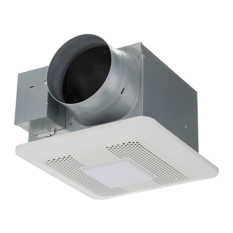
  9. Panasonic FV-07VB1 User manual

Panasonic FV-07VB1 User manual

GENERAL SAFETY INFORMATION -------------------------
2-3
7 V B A 1 A 4 2 0
FV-07VBA1A
b
(ST4.2X20)
(A) For housing can of model: FV-07VBA1A
4
5
Fig.3
INSTALLATION FOR FV-07VBA1(JOIST MOUNTING)
Thermally - protected
(114 Fuse in motor)
C
Thermally - protected
(11 s tor)
Fan body
Junction box
Black
Switch
I-Standard
II-Boost
Capacitor
Earth ground
AC120V 60Hz
Power supply
White
Live
Neutral
Motor
White
Red
Black Black
White
Green
Yellow Yellow
A
B
Fig.4
Switch
A
D
A
P
T
O
RJUNCTION
BOX
Fig.1
Tongue
Conduit
Junction
box
Earth ground
to green
Neutral to white
Live to black
Wire nut
Junction box cover
Fig.2
2. Install the ventilation duct and secure it with a clamp
and seal it with mastic or approved foil tape. A 4 inch
circular duct is needed to connect to the relevant
part of adapter. (Fig. 2)
Conduit
Junction box cover
4. Refer to wiring diagram.
Follow all the local electrical safety codes as well
as the National Electrical Code (NEC). Using UL
approved wire nuts, connect house power wires
to ventilating fan wires.
6. Affix the junction box cover to junction box.
If the knock-out hole is used B , this step
must be performed after step 8.
7. Insert the tongue on the bottom of the
junction box so that it is on the outside of
the fan housing.
8. Affix the junction box to the top of the
fan housing with screw (ST4.2X8). (Fig.4)
Before affixing screw (ST4.2X8), make
sure the tongue of the junction box is
clipped on fan housing correctly. (Fig.3)
Mount junction box cover carefully so
that lead wires are not pinched.
The clamps of the adaptor should b
clipped on fan housing correctly.
Install the adaptor and secure
v duct before installingentilation
junction box.
Mount junction box cover carefully so
that the lead wires are not pinched.
INSTALLATION FOR FV-07VBA1 (JOIST MOUNTING)
6. Select the air volume speed by adjusting the
switch. Factory setting is “I” (Standard) position; preseting
“II” (Boost) selects the high airflow position. (Fig. 4)
INSTALLATION FOR FV-07VBA1A (JOIST MOUNTING)
ST4.2X8 screw
Fig.3
A
Mount junction box cover carefully so
that the lead wires are not pinched.
1. Affix the fan housing to joist 3 long screws
(ST4.2X20) by affixing first 1 screw on the bottom
of the joist, hang up the fan housing through the
key hole, tighten the screw, then affix other
2 screws. (Fig. 1)
3. Remove screw ST4.2X8 from junction box cover
and secure conduit or strain to knock-out hole
( or ). (Fig. 3)
Junction box
cover
5. Affix the junction box cover to junction box with
ST4.2X8 screw.
IMPORTANT:
Remove the tape from adapter before
installation. As shown bellow:
Tape with
ST4.2X20 screws
Damper
Adapter
6
INSTALLATION FOR FV-07VBA1 CONTINUED
Fig.5
7 7/8 (200)
7 7/8 (200)
Ceiling
Housing can
7 7/8 (200)
7 7/8 (200)
Fig.7
The clamps of the adaptor should be clipped
on fan housing correctly.
Install the adaptor and secure ventilation
duct before installing junction box.
Fig.6
10. Finish ceiling work. Ceiling hole should be
aligned with the inside edge of the flange.
(Fig. 5)
After finishing the ceiling job, fill gap between flange and
ceiling with caulk or other sealant to prevent air leakage.
Fig.6
Fan housing
3 Long screws
(ST4.2X20)
Key hole
Stud
3 Long screws
(ST4.2X20)
Fan housing
Key hole
Stud
1. Affix the fan housing to stud with 3 long screws
(ST4.2X20) by affixing first 1 screw in front of the
stud, hang up the fan housing through the key
hole, tighten the screw, then affix other 2 screws.
(Fig. 6)
2. Install the ventilation duct and secure it with a clamp and seal it
with mastic or approved foil tape. A 4 inch circular duct is needed
to connect to the relevant part of adaptor. (Fig 2 of page 5)
5. Affix the junction box cover to junction box with
ST4.2X8 screw.
9. Select the air volume speed by adjusting the switch. Factory setting is "I" (Standard) position;
pressing "II" (Boost) s the high airflow position.elects (Fig.4 of page 5 )
10. Finish wall work. Wall hole should be aligned with the inside edge of the flange. (Fig.7)
Before affixing screw (ST4.2X8), make sure the tongue of the junction box is clipped on
fan housing correctly. (Fig.3 of page 5)
Mount junction box cover carefully so that lead wires are not pinched.
7. Finish the wall work. Ceiling hole should be aligned with
the inside edge of the flange. (Fig. 7)
3. Remove Junction box cover and secure conduit
or strainto junction box cover knock-out hole
( or ). (Fig. 3 of page 5)
B
A
6. Select the air volume speed by adjusting the switch.
Factory setting is “I” (Standard) position; preseting
“II” (Boost) selects the high airflow position.
(Fig. 3 of page 5)
INSTALLATION FOR FV-07VBA1A CONTINUED
INSTALLATION FOR FV-07VBA1(WALL MOUNTING)
7. Finish the wall work. Ceiling hole should be aligned with
the inside edge of the flange. (Fig. 5)
After finishing the wall job, fill gap between
flange and wall with caulk or other sealant
to prevent air leakage.
Housing can
Wall
3. Remove screws ST4.2X8 from Junction box cover
and secure conduit or strain to knock-out hole
( or ). (Fig. 3 of page 5)
4. Refer to wiring diagram.
Follow all the local electrical safety codes as well as the
National Electrical Code (NEC). Using UL approved
wire nuts, connect house power wires to ventilating
fan wires.
Mount junction box cover carefully so
that the lead wires are not pinched.
7. Finish the wall work. Ceiling hole should be aligned with
the inside edge of the flange. (Fig. 5)
7
2.Wash and clean grille assembly.
(Use non-abrasive kitchen detergent, wipe dry with
clean cloth.)(Fig.12)
3. Remove dust and dirt from fan body using a
vacuum cleaner. (Fig.13)
1. Remove grille assembly. (Squeeze mounting springs
and pull down carefully.)(Fig.11)
4. Using a cloth dampened with kitchen detergent,
remove any dirt from Fan Body. Wipe dry with
clean cloth. (Fig.14)
5. Replace grille assembly.
WARNING
CAUTION
Fig.12
Fig.13
Fig.14
Ceiling
Vacuum
cleaner
Ceiling
Glove
Fig.11
INSTALLATION FOR FV-07VBB1
3. Insert the grille assembly mounting springs into the
slots as shown and mount grille assembly to fan body .
(Fig.10) Fig.10
Grille assembly
Grille assembly
Mounting
spring
Slot
Slot
Glove
Glove
Mounting
spring
Fan body
Fig.9
Claw
Rib
Plug connector
Ceiling
2. Secure the blower / motor assembly with 2 screw
and connect the molex plug connector from the
blower to the junction box. (Fig.9)
Before turning on the fan, make sure the
connector is inserted at the correct position.
Failure to properly connect will result in fan not
working.(Fig.9)
The claw of connector must latch to the rib
completely.(Fig.9)
CAUTION
WARNING
The blower / motor assembly must be installed
into housing can tightly by the 2 screw . failure
to secure with screw will affect the grounding.
2 Screw
(ST4.2X8)
Blower / motor assembly
Adaptor
flanges
Ceiling
Fig.8
1. Insert the blower / motor assembly by sliding it into
adaptor flanges. Then press lock the blower / motor
assembly into the housing can until the blower
“clicks” into place for temporary fixation. (Fig.8)
0.7 1.3
1.5
1.5
P0519-0 07VBA1A420
FV-07VBA1
CUBIERTA POSTERIOR
DFHFG{|óÑ}??Ó
INFORMACI
SDF
XFGIJSEF3??{y
DESCRIPCIÓN -------------------------------------------------------------
INSTALACIÓN DEL FV-07VBA1A (MONTAJE EN VIGAS) ---------
INSTALACIÓN DEL FV-07VBA1A (MONTAJE EN PARED) ---------
INSTALACIÓN DEL FV-07VBB1 ----------------------------------------
GUÍA PRÁCTICA PARA LA INSTALACIÓN ----
7 V B A 1 A4 2 0
FV-07VBA1A FV-07VBA1A
(A) Para carcasa metálica del modelo FV-07VBA1A
Fig.1
3 Tornillos largos
(ST4.2X20)
Orificio
L
Abrazaderas
Abrazaderas
Viga
A
D
A
P
T
O
R
JUNCTION
BOX
Fig.2
A
D
A
P
T
O
R
JUNCTION
BOX
1
2
Adaptador
Fig.3
B
A
Conducto
Caja de
conexiones
Cable a tierra
con verde
Neutro con blanco
Polo vivo con negro
Empalmador
roscado
Tapa de la
caja de conexiones
Fig.4
A
D
A
P
T
O
RJUNCTION
BOX
Interruptor
(ST4.2X8)
Tornillo
Caja de conexiones
Carcasa del
ventilador
Carcasa del
ventilador
Cinta adhesiva o metálica
aprobada
Carcasa del
ventilador
Viga
Fig.1
Fig.2
Fig.4
A
D
A
P
T
O
RJUNCTION
BOX
AB
1. Remueva los tornillos que están adjuntados en
el adaptador. Fije la carcasa a la viga con los
3 tornillos largos (ST4.2X20) fijando un tornillo
en la parte inferior de la viga primeramente,
cuelgue la carcasa del ventilador por el orificio,
apriete el tornillo, y fije los otros 2 tornillos. (Fig. 1)
2. Instale el conducto de ventilación, asegúrelo
con una abrazadera y séllelo con masilla o una
cinta metalizada. Deberá usar un conducto
circular de 4 pulgadas para conectarlo a la
parte relevante del adaptador. (Fig 2)
3. Quite la tapa de la caja de conexiones y
coloque el conducto para cables de
alimentación en el orificio correspondiente
de la tapa de la caja de conexiones. ( y ). (Fig. 3)
4. Refiérase al diagrama de cableado que
figura a continuación. Cumpla con los
códigos locales sobre instalaciones eléctricas
y con el Código Nacional para las instalaciones
Eléctricas (”NEC”, por sus siglas en inglés). Use
empalmadores roscados aprobados por UL
para conectar los cables de suministro de
electricidad con los cables del ventilador.
5. Fije la tapa a la caja de conexiones.
Fig.3
Caja de
conexiones
Fig.3
AB
6. Seleccione el volumen de la velocidad del
aire con el interruptor de ajuste. El ajuste de
fábrica es la posición “I” (Estándar); si
presiona “II” (Aumento) se pone en la
posición de flujo de aire alto. (Fig. 4)
Vuelva a colocar la tapa de la caja de
conexiones cuidando de no atrapar los cables.
AB
1. Fije la carcasa a la viga con los 3 tornillos
largos (ST4.2X20) fijando un tornillo en la
parte inferior de la viga primeramente,
cuelgue la carcasa del ventilador por el orificio,
apriete el tornillo, y fije los otros 2 tornillos.
(Fig. 1)
Tapa de
conexiones
Fig.5
7 7/8 (200)
7 7/8 (200)
(MONTAJE DE PARED)
7 7/8 (200)
(
8
/
7
7)
0
0
2
Fig.7
Fig.6
Orificio
Taco
3 Tornillos largos
(ST4.2X20)
Carcasa del
ventilador
7. Termine el trabajo en la pared. El orificio en la pared debe estar alineado con el
borde interior del reborde. (Fig. 7)
Carcasa del ventilador
Orificio
Tres tornillos largos
(ST4.2X20)
Fig.6
1. Fije la carcasa del ventilador al taco con 3 tornillos
largos (ST4.2X20) fijando un tornillo en la parte
frontal del taco primeramente, cuelgue la carcasa
del ventilador a través del orificio y, a continuación,
apriete el tornillo, fije los otros 2 tornillos. (Fig. 6)
2. Instale el conducto de ventilación, asegúrelo con
una abrazadera y séllelo con masilla o una cinta
metalizada. Deberá usar un conducto circular de 4
pulgadas para conectarlo a la parte relevante del
adaptador. (Fig 2 de página 5)
3. Quite la tapa de la caja de conexiones y coloque el
conducto para cables de alimentación en el orificio
correspondiente de la tapa de la caja de conexiones.
( o ). (Fig. 3 de página 5)
4. Refiérase al diagrama de cableado que figura a
continuación. Cumpla con los códigos locales sobre
instalaciones eléctricas y con el Código Nacional
para las instalaciones Eléctricas (”NEC”, por sus siglas
en inglés). Use empalmadores roscados aprobados por
UL para conectar los cables de suministro de electricidad
con los cables del ventilador.
AB
5. Fije la tapa a la caja de conexiones.
Vuelva a colocar la tapa de la caja de conexiones cuidando de no atrapar los cables.
INSTALACIÓN DEL FV-07VBA1A (CONTINUACIÓN)
INSTALACIÓN DEL FV-07VBA1A (MONTAJE DE PARED)
Vigueta
7. Finalice el trabajo en el cielorraso. El orificio
del cielorraso debe quedar alineado con los
bordes internos de la brida. (Fig. 5)
AB
Fig.11
Rejilla
Ranura
Guante
Resorte de
montaje
Fig.12
Fig.13
Cielorraso
Aspiradora
Fig.14
Cielorraso
Guanta
Bridas del
adaptador
Cielorraso
Fig.8
Fig.9
Gancho
Costilla
Conector
Cielorraso
2 Tornillo
(ST4.2X8)
Fig.10
Rejilla
Resorte de
montaje
Ranura
Guante
Carcasa
0. 7 1.3
1.5
P0816-0 07VBA1M423
1.5
2019
2019

Other manuals for FV-07VB1

3

Other Panasonic Fan manuals

Panasonic FV-NLF46RES User manual

Panasonic

Panasonic FV-NLF46RES User manual

Panasonic FV-11VH1 User manual

Panasonic

Panasonic FV-11VH1 User manual

Panasonic FV-30BG3H User manual

Panasonic

Panasonic FV-30BG3H User manual

Panasonic FV-04VE1 User manual

Panasonic

Panasonic FV-04VE1 User manual

Panasonic FV-08VFL2 User manual

Panasonic

Panasonic FV-08VFL2 User manual

Panasonic 2006ML-04W-B20 User manual

Panasonic

Panasonic 2006ML-04W-B20 User manual

Panasonic FV-07VF1 Operation and maintenance manual

Panasonic

Panasonic FV-07VF1 Operation and maintenance manual

Panasonic FV-0810RS1 User manual

Panasonic

Panasonic FV-0810RS1 User manual

Panasonic F-M15EX User manual

Panasonic

Panasonic F-M15EX User manual

Panasonic WhisperGreen FV-08VKML3 User manual

Panasonic

Panasonic WhisperGreen FV-08VKML3 User manual

Panasonic FV-20CUT1 User manual

Panasonic

Panasonic FV-20CUT1 User manual

Panasonic F-M14HW User manual

Panasonic

Panasonic F-M14HW User manual

Panasonic FV-10VEC2R User manual

Panasonic

Panasonic FV-10VEC2R User manual

Panasonic F-25UGA User manual

Panasonic

Panasonic F-25UGA User manual

Panasonic FV-11VH1 User manual

Panasonic

Panasonic FV-11VH1 User manual

Panasonic FV-05-11VKL1 User manual

Panasonic

Panasonic FV-05-11VKL1 User manual

Panasonic F-30PLH User manual

Panasonic

Panasonic F-30PLH User manual

Panasonic FV-15AUL1 User manual

Panasonic

Panasonic FV-15AUL1 User manual

Panasonic F-M15AC User manual

Panasonic

Panasonic F-M15AC User manual

Panasonic F-M15EC User manual

Panasonic

Panasonic F-M15EC User manual

Panasonic EcoVent FV-07VBA1 User manual

Panasonic

Panasonic EcoVent FV-07VBA1 User manual

Panasonic Whisper Value-Lite FV-10VSL2 User manual

Panasonic

Panasonic Whisper Value-Lite FV-10VSL2 User manual

Panasonic F-M15F1 User manual

Panasonic

Panasonic F-M15F1 User manual

Panasonic RG-C811A User manual

Panasonic

Panasonic RG-C811A User manual

Popular Fan manuals by other brands

Aertesi SOFFIO Series Installation, use and maintenance manual

Aertesi

Aertesi SOFFIO Series Installation, use and maintenance manual

BLAUBERG Ventilatoren Iso user manual

BLAUBERG Ventilatoren

BLAUBERG Ventilatoren Iso user manual

HIDRIA 0310-4-0071 user guide

HIDRIA

HIDRIA 0310-4-0071 user guide

Harbor Breeze SARATOGA user manual

Harbor Breeze

Harbor Breeze SARATOGA user manual

Sulion 2181387 manual

Sulion

Sulion 2181387 manual

Kogan KADCPEDFANA user manual

Kogan

Kogan KADCPEDFANA user manual

Akerstedts FML instructions

Akerstedts

Akerstedts FML instructions

BREMMER TF-K2907 user manual

BREMMER

BREMMER TF-K2907 user manual

Hydro Crunch 6 INCH 2 SPEED CLIP FAN instruction manual

Hydro Crunch

Hydro Crunch 6 INCH 2 SPEED CLIP FAN instruction manual

Hunter Hartland installation manual

Hunter

Hunter Hartland installation manual

Master MF 30 DV User and Maintenance Book

Master

Master MF 30 DV User and Maintenance Book

NuAire MEVDC installation manual

NuAire

NuAire MEVDC installation manual

Draper 19406 quick start guide

Draper

Draper 19406 quick start guide

Field Controls FIELD DIRECT VENT SYSTEM REDUCING TEE manual

Field Controls

Field Controls FIELD DIRECT VENT SYSTEM REDUCING TEE manual

ICE AIR FCHC installation manual

ICE AIR

ICE AIR FCHC installation manual

Vent-Axia VASF100B Installation and wiring instructions

Vent-Axia

Vent-Axia VASF100B Installation and wiring instructions

Minka-Aire VINTAGE GYRO Instruction manual warranty certificate

Minka-Aire

Minka-Aire VINTAGE GYRO Instruction manual warranty certificate

Kompernass KH 1151 operating instructions

Kompernass

Kompernass KH 1151 operating instructions

manuals.online logo
manuals.online logoBrands
  • About & Mission
  • Contact us
  • Privacy Policy
  • Terms and Conditions

Copyright 2025 Manuals.Online. All Rights Reserved.