SALUPO SQ707.00 Manual

CODE
SQ707.xx
REV. 2
06/06/2018
INVERTER IRIS BLUE
MADE IN ITALY
MANUALE DI ISTRUZIONE E INSTALLAZIONE
INSTRUCTION AND INSTALLATION MANUAL
ITA/ENG
It is mandatory to connect the system ground cable to the panel.
In some cases, the connection fails, may invalidate the warranty.
È obbligatorio collegare il cavo di terra dell’impianto al quadro.
In alcuni casi, il mancato collegamento, può far decadere la garanzia.

1. Istruzioni generali per l’installazione...................
2. Avvertenze.........................................................
3. Caratteristiche generali .....................................
4. Caratteristiche elettriche e meccaniche.............
5. Schema di collegamento SQ707.xx....................
6. Programmazione...............................................
6.1 Programmazione marcia a secco..............
7. Parametri di default............................................
8. Esempio funzionale di un impianto idraulico
semplice............................................................
9. Dichiarazione di conformità..............................
2
INDICE
INDEX
General instructions for installing...................3
Warnings........................................................4
General characteristics..................................5
Electrical and mechanical characteristics......6
Wiring diagram SQ707.xx...............................7
Programming........................................10
Dry running programming........................13
Default parameters.......................................14
Functional exemple of a simple hydraulic
system.........................................................15
Declaration of conformity.............................16

Assicurarsi che la linea sia protetta, secondo le
normative, in funzione dell'applicazione.
Accertarsi che la potenza e la corrente di targa
del motore rispecchino i limiti di impiego del
quadro.
Installare il quadro in ambienti adatti al suo
grado di protezione IP54. Per il fissaggio
dell'involucro, utilizzare gli appositi fori già
presenti o predisposti sul fondo. Nell'effettuare
il fissaggio dell'involucro fare molta attenzione
a non toccare o danneggiare i vari componenti.
Eliminare qualsiasi tipo di impurità metallica e/o
plastica che dovesse casualmente cadere
all'interno dell'involucro (viti, rondelle,
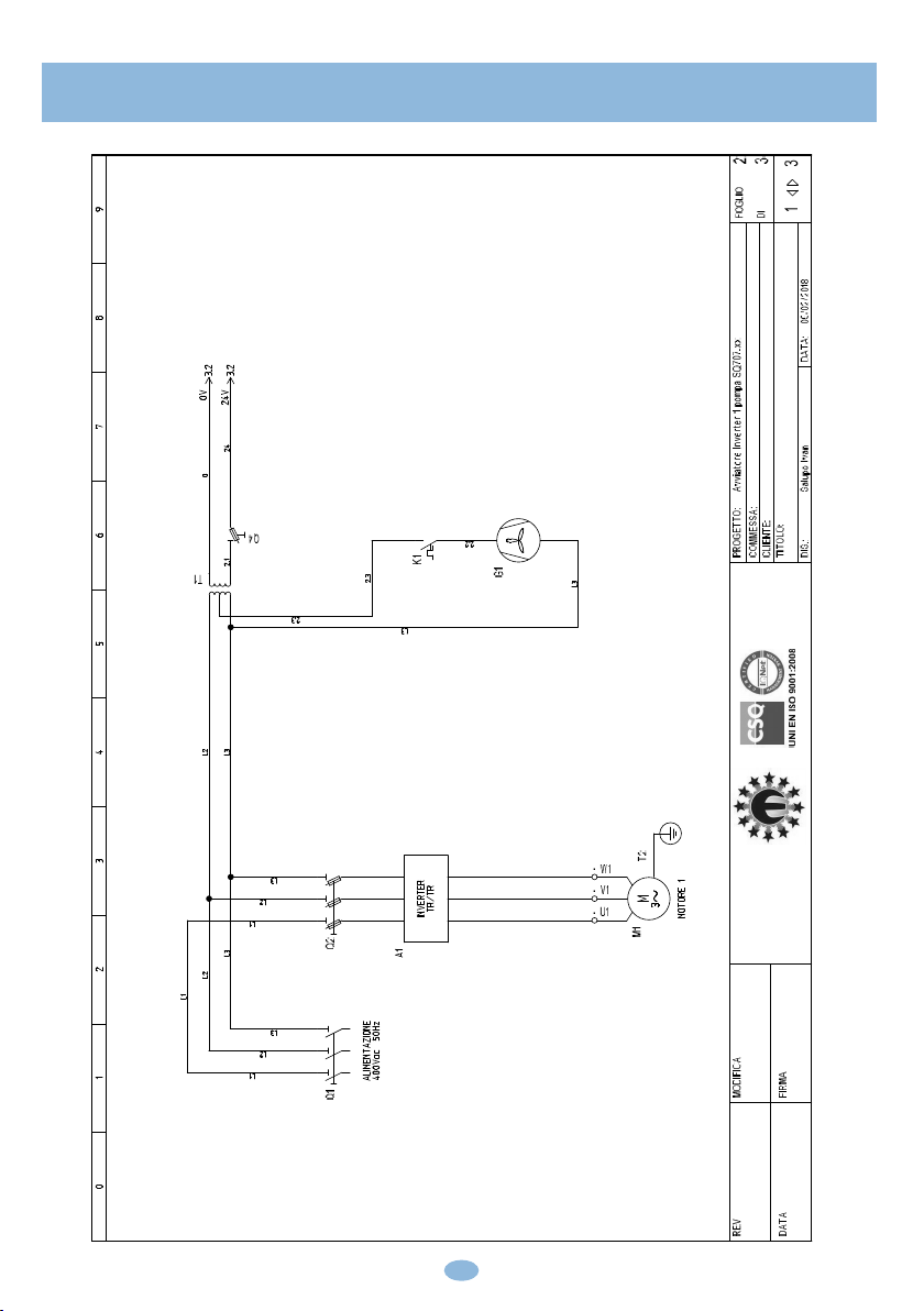
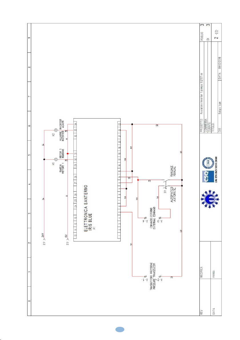
polvere…). Effettuare i collegamenti elettrici
rispettando gli schemi di collegamento.
Nel fissare i cavi sulle morsettiere, adoperare
attrezzi di giuste misure e dimensioni evitando
di danneggiare i morsetti metallici e le relative
sedi. Prima di qualsiasi operazione da
effettuare all'interno, escludere l'alimentazione
generale.
Le operazioni di regolazione all'interno del
quadro devono essere svolte da personale
qualificato. In caso di intervento delle protezioni
verificarne la causa prima del ripristino.
In caso di necessità sostituire i vari componenti
solo con altri aventi le stesse caratteristiche e
portate di quelli originali.
È compito dell'installatore verificare
l'apparecchiatura dopo l'installazione
nonostante questa sia già stata sottoposta
regolarmente a prove dal costruttore.
Il costruttore declina ogni responsabilità
per sinistri a cose o persone dovuti a
manomissioni delle apparecchiature da
parte di personale non autorizzato o da
carenze nella manutenzione e riparazione.
Make sure power supply is protected up to
standard depending on application. The power
of the motor has to be within the control panel's
limits of use.
Install the control panel in an environment
appropriate to its IP54 degree of protection.
In order to fix the box, use the appropriate holes
which are present or suggested on the bottom.
Pay particular attention to not touching or
damaging any components while fixing the box.
Eliminate whatever metal and/or plastic
impurity which could happen to fall inside the
box (screws, washers, dust…).
When connecting electric cables, follow the
wiring diagrams.
When fixing the cables in the terminal board
use tools of correct size to avoid damaging the
metal feed clamps and their sockets.
Before acting upon anything inside, disconnect
power supply. Regulation procedures must be
carried out by qualified personnel. In case
protections intervene verify the cause of the
problem before resetting.
If necessary substitute the various components
only with those having the same characteristics
and components as the originals.
It is the installer' s duty to verify the device
after the installation although it has already
u n d e r g o n e r e g u l a r t e s t i n g b y t h e
manufacturer.
The manufacturer is released from all
responsibilities for accidents to things or
people, which derive from misuse of the
devices by unauthorized personnel or from
lack of maintenance and repair.
1. ISTRUZIONI GENERALI PER L’INSTALLAZIONE
1. GENERAL INSTRUCTIONS FOR INSTALLING
3

2. AVVERTENZE
2. WARNINGS
4
SCOSSE ELETTRICHE
Rischio di scosse elettriche se non osservate quanto
prescritto.
ELECTRIC SHOCKS
Risk of electric shocks if not complied with the
requirements.
PERICOLO
Rischio di danni alle persone, e alle cose se non
osservate quanto prescritto.
DANGER
Risk of personal injury and property if not complied
with the requirements.
AVVERTENZA
Prima di installare e utilizzare il prodotto leggere
attentamente il presente manuale in tutte le sue parti.
L'installazione e la manutenzione devono essere
eseguite da personale qualificato nel rispetto delle
norme vigenti.
Il costruttore non risponde di danni provocati da un uso
improprio o proibito del quadro e declina ogni
responsabilità per danni provocati da una non corretta
installazione e manutenzione dell’impianto. L'uso di
ricambi non originali, manomissioni o usi impropri
fanno decadere la garanzia.
WARNING
Before installing and using the product read this book
in all its parts. Installation and maintenance must be
performed by qualified personnel in accordance with
current regulations.
The manufacturer will not be held responsible for any
damage caused by improper or prohibited use of this
control panel and is not responsible for any damages
caused by an incorrect installation or maintenance of
the plant. The use of non-original spare parts,
tempering or improper use, make the product warranty
null.
AVVERTENZA
Accertarsi che la potenza di targa del motore sia
all'interno dei limiti di impiego del quadro.
Installare il quadro in ambienti idonei al suo grado di
protezione IP54.
Per l'intervento all'interno del quadro usare attrezzi
adeguati per evitare danni alle morsettiere.
WARNING
Be sure that the power of the motor is within the control
panel range.
Install the control panel in an environment appropriate
to its IP54 degree of protection.
To operate inside the control panel use tools of correct
size to avoid damaging the sockets.
PERICOLO
Prima di ogni intervento accertarsi che il quadro sia
scollegato dall'alimentazione elettrica.
Non effettuare manovre con il quadro aperto.
Il quadro deve essere collegato ad un efficiente
impianto di terra.
Per il fissaggio del quadro usare gli appositi fori, non
danneggiare i componenti interni ed eliminare
eventuali detriti di lavorazione all'interno del quadro.
In caso di intervento delle protezioni eliminare la causa
del malfunzionamento prima di effettuare il ripristino.
DANGER
Before any intervention ensure that the control panel is
disconnected from the electricity supply.
Do not attempt operations when the control panel is
open.
The control panel must be connected to an efficient
earthing system.
In order to fix the box use the appropriate holes present
on the bottom, don't damage internal components and
eliminate any working debris inside the box.
In the case of protections eliminate the cause of the
malfunction before the restoration.

3. CARATTERISTICHE GENERALI
3. GENERAL CHARACTERISTICS
5
- Tensione di funzionamento 400Vac ±10% 50/60Hz
- Sezionatore generale con blocca porta
- Selettore per il funzionamento automatico - manuale
- Spia Led marcia
- Spia Led allarme inverter
- Display fronte quadro per la programmazione e la
visualizzazione dei parametri
- Fusibile di protezione circuito ausiliario
- Trasformatore per circuito ausiliario
- Fusibile di protezione inverter
- Inverter completo di kit remoto
- Funzioni principali per il sistema di pompaggio e
trattamento acque:
Controllo del livello Riempimento/Svuotamento
Doppia rampa iniziale
Controllo riempimento tubature
Fire mode (funzionamento forzato in caso di
allarme)
Sleep/wake up mode (prolunga il tempo di ritardo
pompa per far risparmiare energia)
Safe Torque Off (funzione per l'arresto a ruota
libera)
Funzionamento PID
- Ventilazione forzata completa di filtri
- Termostato per ventola
- Contenitore esterno in metallo IP54
- Temperatura d'impiego -5/+40°C
Ingressi/Uscite
- Ingresso 4-20mA
- Ingresso in bassissima tensione per comando esterno
Regolazioni
- Multilingua
- Potenza nominale motore
- Corrente nominale motore
- Soglia marcia a secco
Protezioni
- Marcia a secco con cosφ
- Controllo perdita di pressione
- Amperometrica
- Termica motore
- Sovraccarico motore
- Sovraccarico inverter
- Surriscaldamento inverter
- Tensione minima inverter
- Tensione massima inverter
- Operating voltage 400Vac ±10% 50/60Hz
- General disconnecting switch with door lock
- Selector switch for automatic - manual operation
- Running Led indicator
- Inverter alarm Led indicator
- Front display to program and visualize the parameters
- Auxiliary circuit protection fuse
- Transformer for auxiliary circuit
- Inverter protection fuse
- Inverter complete with remote kit
- Main functions for the pumping system and water
treatment:
Level control Filling/Emptying
Double initial ramp
Pipes filling control
Fire mode (forced operation in case of alarm)
Sleep/wake up mode (it prolongs the pump delay
time to save energy)
Safe Torque Off (function for the freewheel stop)
PID functioning
- Forced ventilation complete with filters
- Thermostat for fan
- External metal box IP54
- Operating temperature -5/+40°C
Inputs/Outputs
- Input 4-20mA
- Very low voltage input for external command
Adjustments
- Multilingual
- Motor rated power
- Motor rated current
- Dry running threshold
Protections
- Dry running with cosφ
- Loss of pressure control
- Amperometric
- Motor thermal
- Motor overload
- Inverter overload
- Inverter overheating
- Inverter minimum voltage
- Inverter maximum voltage

THREE-PHASE
CODE WEIGHT
A B CKW HP
POWER DIMENSIONS
Kg
4. CARATTERISTICHE ELETTRICHE E MECCANICHE
4. ELECTRICAL AND MECHANICAL CHARACTERISTICS
6
CURRENT
OPERATING
SQ707.00/01
SQ707.02
10,5
12,5
3/5,5
7,5
2,2/4
5,5
SQ707.03
SQ707.04
16,5
27
10
15
7,5
11
SQ707.05
SQ707.06
30
41
20
25
15
18,5
24
24
26
41
41
41
SQ707.07
SQ707.08
57
60
30
40
22
30
SQ707.09 80
50
37
41
43
91
400
600
250
400
600
250
400
600
250
600
800
250
600
800
250
600
800
250
250
600
800
600
800
250
800
1000
400
SQ707.10 88
60
45
SQ707.11
SQ707.12
120
135
75
100
55
75
100
110
120
SQ707.13
SQ707.14
195
215
125
150
92
110
SQ707.15 240
180
132
180
190
200
800
1200
400
800
1200
400
800
1200
400
500
800
1800
800
1800
500
800
1800
500
SQ707.16 300
220
160 210
800
1800
500

5. SCHEMA DI COLLEGAMENTO SQ707.xx
5. WIRING DIAGRAM SQ707.xx
7

8

9

Nella schermata seguente (fig. 1) è possibile
visualizzare le diverse unità di misura con il
seguente ordine:
Frequenza motore (0.0Hz);
Corrente assorbita (0.0A);
Pressione impianto (0.00bar);
Pressione di riferimento (3.00bar).
6. PROGRAMMAZIONE
6. PROGRAMMING
10
(Fig. 1)
Come si può vedere, la pressione di riferimento
è impostata di default a 3.00 bar. Questo
significa che quando la pressione di riferimento
arriverà a 3.00 bar, l'inverter comincerà a
modulare fino a quando supererà i 3.00 bar e
nello stesso tempo la frequenza del motore
arriverà alla percentuale di PID minimo (P237
default 70% = 35Hz). Dopo circa 20s l'inverter
si spegnerà in modo totalmente automatico. A
questo punto si ritroverà in una modalità
chiamata SLEEP e ripartirà nel momento in cui
la pressione dell'impianto scenderà al di sotto
della pressione di SETPOINT meno la
percentuale di risveglio (P237b default 5% =
0.5 bar).
Es. P237b = 5% = 0.5bar
PRef = 3.00bar
Soglia di accensione pompa = 3.00 - 0.5 =
2.5bar
In the following screen (fig.1) it’s possible to see
the different unit of measure with the following
order:
Motor frequency (0.0Hz);
Current consumption (0.0A);
Plant pressure (0.00bar);
Reference pressure (3.00bar).
As you can see, the pressure of reference will
be default to 3.00bar.
This means that, when the reference pressure
reaches 3.00 bar the inverter will start to
modulate until it exceeds 3.00 bar and in the
meanwhile the motor frequency will reaches
the percentage of minimum PID (P237 default
70% = 35Hz). After about 20 minutes the
inverter will turn off completely automatically.
At this point it will be in a mode called SLEEP
and will start when the system pressure will fall
below the SETPOINT pressure less the rate of
awakening (P237 default 5% = 0.5 bar).
Es. P237 b= 5%=0.5 bar
PRef= 3.00 bar
Pump ignition threshold = 3.00 - 0.5 = 2.5 bar

Per poter modificare la pressione di riferimento
e portarla ad esempio a 4.00 bar, non
bisognerà fare altro che cliccare, come nella
fig. 2, il pulsante “MENÙ”
11
(Figura 2)
e una volta che comparirà PRef (fig. 3) basterà
cliccare la freccia ▲ o ▼ per aumentare o
diminuire la pressione di riferimento.
Una volta impostata la pressione desiderata,
bisognerà premere il tasto ENTER e il
p a r a m e t r o v e r r à a u t o m a t i c a m e n t e
memorizzato.
(Fig. 3)
(Fig. 2)
In order to change the reference pressure and
carry it for example to 4.00 bar, you just have to
click on the “MENÙ” button as shown in fig.2
Once you see Pref (fig.3) just click on the arrow
▲or ▼ to increase or decrease the reference
pressure.
Once the desidered pressure is set, you will
need to press the ENTER key and the
parameter will automatically be stored.

Successivamente alla pressione di riferimento,
bisognerà programmare in modo particolare i
seguenti parametri:
C017 (potenza nominale motore 1);
C018 (corrente nominale motore 1).
Per fare questo, si dovrà cliccare il pulsante
“START-UP”, così facendo, comparirà una
schermata come quella della fig. 4.
12
(Fig. 4)
Per modificare i parametri descritti in
precedenza (C017 e C018), bisognerà cliccare
il tasto “ENTER” e spostarsi con la freccia ▲
nella schermata dove compare scritto
“C017…”, premere ENTER e con le frecce ▲ -
▼ impostare la potenza nominale del motore e
infine cliccare nuovamente ENTER per
memorizzare il parametro.
Subito dopo, con la freccia ▲, spostarsi nel
parametro “C018…” e ripetere la stessa
procedura che è stata descritta in precedenza
per la memorizzazione del parametro C017.
Per tornare al menù principale bisognerà
cliccare la freccia ▲ fino alla fine del menù
After having set the reference pressure, you
have to program in particular the following
parameters:
C017 (motor 1 rated power )
C018 (motor 1 rated current )
To do this, you will have to click the
"START-UP" key, in this way a screen like that
of fig.4 will appear.
To modify the parameters described in
precedence (C017 and C018), it will be
necessary to click the "ENTER" key and move
with the arrow ▲ in the screen where "C017 ..."
appears, then press ENTER and set the rated
motor power through the arrows ▲ -▼. Finally
click ENTER again to store the parameter.
At this point, move to the parameter "C018 ..."
through the ▲ arrow, and repeat the same
procedure described above for storing the
C017 parameter.
To return to the main menu you will need to
click the arrow ▲ until the end of the menu.

L'inverter Iris Blue può essere programmato
anche per intervenire quando il motore gira a
secco.
Di default già viene programmato, ma è bene
che una volta messo in funzione l'impianto si
vadano a rivedere alcuni parametri relativi a
questa funzione.
Di seguito sono riportati i parametri interessati
per questa funzione, essi si trovano nel menù
“PAR” all'interno del sottomenù
“CONTROLLO MARCIA A SECCO”:
P710b (cos φ Soglia marcia a secco a
frequenza bassa) = default 0.20;
P710d (cos φ Soglia marcia a secco a
frequenza alta) = default 0.20;
P712 (Tempo di intervento) = default 20 s;
P713 (Tempo di autoreset) = 0 s.
Prima di impostare i parametri P710b e P710d,
bisogna far partire l'inverter in modalità
MANUALE e una volta raggiunta la frequenza
di 50Hz, controllare il valore del cos φ misurato
nel menù “MEA” all'interno del sottomenù
“MISURE MOTORE” parametro “M027A” .
Individuato il valore, bisogna calcolarne il 30%
in meno e inserirlo nei parametri P710b e
P710d.
Es. M027A = 0.65
P710b e P710d =0.65 -[(0.65/100)*30] = 0.455
Per tornare al menù principale bisogna cliccare
due volte il tasto ESC e una volta il tasto MENÙ.
13
6.1 PROGRAMMAZIONE MARCIA A SECCO
6.1 DRY RUNNING PROGRAMMING
The Iris Blue inverter can be programmed
also to intervene in case of dry running.
By default it is already programmed but it is
recommended, after putting the system into
operation, to review some parameters related to
this function.
The parameters concerning this function are
shown below,you can find them in the menu
"PAR" inside the submenu "DRY RUNNING
CONTROL":
P710b (cos φ Dry running threshold at
low frequency) = default 0.20;
P710d (cos φ Dry running threshold at
high frequency) = default 0.20;
P712 (Intervention time) = default 20 s;
P713 (Autoreset time) = 0 s.
Before setting the parameters P710b and
P710d, you have to start the inverter in
MANUAL mode and once the frequency of 50Hz
is reached, check the value of the
cos φ measured in the "MEA" menu inside the
submenu "MOTOR MEASURES" parameter
“M027A".
Once the value has been identified, you need to
calculate the 30% less and enter it in parameters
P710b and P710d.
Ex. M027A = 0.65
P710b and P710d = 0.65 - [(0.65 / 100) * 30] =
0.455
To return to the main menu, click
twice the ESC key and once the MENU key.

P001 = engineering
P265 = Keypad
P266d = bar
P266e = 0
P266f = 10 bar
P267 = bar
P269 = SI
P009 = 3sec
P010 = 3sec
P018 = 1sec
P019 = 1sec
P020 = 60 %
P059 = 250ms
C013 = quadratica
C016 = …rpm
C017 = …kW
C018 = …. A
C144 = disabilitato
C265 = no declass
C291 = normale
C285 = tastiera
C288 = AIN1 5-6
P237 = 70%
P237a = err>P237b
P237b = 5%
P240 = 1.000
P242 = 500*Tc (ms)
P255 = 20s
P255a = 0%
P255b = 100%
P255c = 75% P237)
P255d = 78%
P257 = 0.100 Trasduttore 10 bar (0,160 16 bar)
P288 = digital
P289 = inverter run ok
P296 = true
P297 = digital
P298 = Inverter alarm
P305 = true
Programmazione uscita digitale software (pompa in manuale
a frequenza fissa 1500rpm)
P081 = 1500 RPM
P350 = DOUBLE DIGITAL
P351 = MDI 1
P352 = MDI4
C182= ENABLE
C149 = MPL1
C171 = MDI4
GESTIONE 3 SETPOINT DIFFERENTI DOVE E' PREVISTO
C188a = MDI4;
C188b = MDI7;
C188c = MDI8;
P081a = ….bar (primo riferimento setpoint);
P082a =… bar(secondo riferimento setpoint);
P084a = …..bar (terzo riferimento setpoint) ;
PROTEZIONE MARCIA A SECCO DOVE È RICHIESTA
P710 = Fattore di potenza (cosfi)
P710a = 0.00%fnom
P710b = 0.30
P710c = 100.00%fnom
P710d = 0.30
P712 = tempo intervento = 6s
P713 = tempo di autoreset 0 = (disattivato)
P714 = costante di tempo filtro grandezza = 300ms
P715 = input digitale per disable = disable
P716 = azione di intervento = allarme
M027A = schermata che visualizza il cosfi
Programmazione Allarme perdita di pressione
P720 = 0
P721 = corrisponde alla pressione minima in percentuale con la
scala del trasduttore.
P722 = Tempo di intervento = 30s
P723 = 1 Si verificherà l'allarme con il successivo blocco della
pompa
Es. Se si vuole far spegnere la pompa quando scende al di sotto
di 2.00 bar
Trasduttore 0 - 10 bar
P721 = 10 / 100 * 20 = 2 bar = 20%
Trasduttore 0 - 16 bar
P721 = 16 / 100 * 12.5 = 2 bar = 12.5%
M38U = visualizzare la pressione
7. PARAMETRI DI DEFAULT
7. DEFAULT PARAMETERS
14

8. ESEMPIO FUNZIONALE DI UN IMPIANTO IDRAULICO SEMPLICE
8. FUNCTIONAL EXEMPLE OF A SIMPLE HYDRAULIC SYSTEM
15

Il costruttore:
Salupo S.a.s.
Via Laganeto, 129
98070 Rocca di Capri Leone (ME)
Dichiara che:
i quadri inverter Inverter Iris Blue
sono conformi ai requisiti di protezione in
materia di sicurezza (bassa tensione) e di
compatibilità elettromagnetica specifici previsti
dalle Direttive della Comunità Europea
2006/95/C E E d e l 1 6 Gennaio 2007,
2004/108/CE del 10 Novembre 2007,
93/68/CEE del 22 Luglio 1993. Conformità
CEI EN60439-1, EN 61000-6-3, EN 61000-6-1
DIN VDE 0113/EN60204-1 / IEC 204-1.
The manufacturer:
Salupo S.a.s.
Via Laganeto, 129
98070 Rocca di Capri Leone (ME)
Declares that:
the Inverter Iris Blue control panels
com pl y w i th the s pe cif i c prot ection
prerequisites concerning both safety (low
voltage) and the electromagnetic compatibility
provided for by the European Community laws
2006/95/CEE of 16th January 2007,
2004/108/CE of 10th November 2007,
93/68/CEE of 22th July 1993. Compliance
CEI EN60439-1, EN 61000-6-3, EN 61000-6-1
DIN VDE 0113/EN60204-1 / IEC 204-1.
9. DICHIARAZIONE DI CONFORMITÁ
9. DECLARATION OF CONFORMITY
16
SALUPO S.A.S.
Responsabile Ufficio Tecnico
P.I. Salupo Ivan
SALUPO S.A.S.
Technical Dep. Manager
P.I. Salupo Ivan

________________________________________________
________________________________________________
________________________________________________
________________________________________________
________________________________________________
________________________________________________
________________________________________________
________________________________________________
________________________________________________
________________________________________________
________________________________________________
________________________________________________
________________________________________________
________________________________________________
________________________________________________
________________________________________________
________________________________________________
________________________________________________
17
NOTE

________________________________________________
________________________________________________
________________________________________________
________________________________________________
________________________________________________
________________________________________________
________________________________________________
________________________________________________
________________________________________________
________________________________________________
________________________________________________
________________________________________________
________________________________________________
________________________________________________
________________________________________________
________________________________________________
________________________________________________
________________________________________________
18
NOTE

________________________________________________
________________________________________________
________________________________________________
________________________________________________
________________________________________________
________________________________________________
________________________________________________
________________________________________________
________________________________________________
________________________________________________
________________________________________________
________________________________________________
________________________________________________
________________________________________________
________________________________________________
________________________________________________
________________________________________________
________________________________________________
19
NOTE

SALUPO
Via Laganeto, 129
98070 Rocca di Caprileone (ME) ITALY
Tel.:+39 - (0) 941 - 950216
Fax:+39 - (0) 941 - 958777
www.salupoquadri.com
[email protected]e-mail:
UNI EN ISO 9001:2008
This manual suits for next models
17
Table of contents
Other SALUPO Inverter manuals
Popular Inverter manuals by other brands

Samil Power
Samil Power SolarLake 5500TL-PM manual

UNIRAC
UNIRAC SOLARMOUNT ASCENDER 2-ROW ELEVATED installation guide

Solar Technology
Solar Technology SolarMate ARENALight SMAL001 user manual

Sunerg Solar Energy
Sunerg Solar Energy XMCH66400BW+H installation manual

Hyundai Electric
Hyundai Electric N800 Series installation manual

JALpower
JALpower JSI-10KTL owner's manual