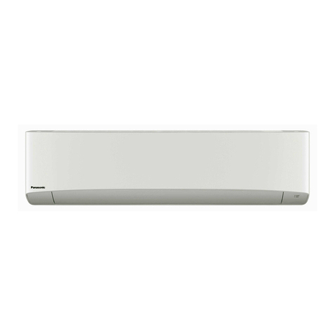
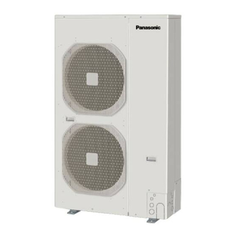
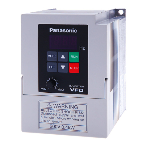
Panasonic S-200PE2E5 Manual

85464849294004 REFERENCE NO. SM830194-04
TECHNICAL DATA& SERVICE MANUAL
Outdoor UnitIndoor Unit
S-200PE1E8A, S-200PE1E8, S-250PE1E8
Type E1
S-200PE2E5, S-250PE2E5
Type E2
U-200PE1E8, U-250PE1E8
SM830194-11CE
SM830194-04_Single_BigPAC.indb 1 2014/10/31 13:33:22

i
IMPORTANT!
Please Read Before Starting
This air conditioner must be installed by the sales dealer
or installer.
This information is provided for use only by authorized
persons.
For safe installation and trouble-free operation, you must:
●Carefully read this instruction booklet before beginning.
●Follow each installation or repair step exactly as shown.
●This air conditioner shall be installed in accordance with
National Wiring Regulations.
●Pay close attention to all warning and caution notices
given in this manual.
WARNING
This symbol refers to a hazard or unsafe
practice which can result in severe
personal injury or death.
CAUTION
This symbol refers to a hazard or unsafe
practice which can result in personal injury
or product or property damage.
If Necessary, Get Help
These instructions are all you need for most installation
sites and maintenance conditions. If you require help for a
special problem, contact our sales/service outlet or your
certified dealer for additional instructions.
In Case of Improper Installation
The manufacturer shall in no way be responsible for
improper installation or maintenance service, including
failure to follow the instructions in this document.
SPECIAL PRECAUTIONS
WARNING
WARNING When Wiring
WARNING
Risk of Electric Shock
ELECTRICAL SHOCK CAN
CAUSE SEVERE PERSONAL
INJURY OR DEATH. ONLY A
QUALIFIED, EXPERIENCED
ELECTRICIAN SHOULD
ATTEMPT TO WIRE THIS
SYSTEM.
•Donotsupplypowertotheunituntil
all wiring and tubing are completed or
reconnected and checked.
•Highlydangerouselectricalvoltagesare
used in this system.
Carefully refer to the wiring diagram and
these instructions when wiring. Improper
connections and inadequate grounding
can cause accidental injury or death.
•Connectallwiringtightly.Loosewiring
may cause overheating at connection
points and a possible fire hazard.
•Provide a power outlet to be used
exclusively for each unit.
•Provide a power outlet exclusively for
each unit, and full disconnection means
having a contact separation in all poles
must be incorporated in the fixed wiring
in accordance with the wiring rules.
•To prevent possible hazards from
insulation failure, the unit must be
grounded.
•This equipment is strongly recommended
to be installed with Earth Leakage
Circuit Breaker (ELCB) or Residual
Current Device (RCD). Otherwise, it may
cause electrical shock and fire in case
of equipment breakdown or insulation
breakdown.
When Transporting
Be careful when picking up and moving
the indoor and outdoor units. Get a partner
to help, and bend your knees when lifting
to reduce strain on your back. Sharp
edges or thin aluminum fins on the air
conditioner can cut your fingers.
When Installing…
Select an installation location which is
rigid and strong enough to support or hold
the unit, and select a location for easy
maintenance.
…In a Room
Properly insulate any tubing run inside a
room to prevent “sweating” that can cause
dripping and water damage to walls and
floors.
WARNING
CAUTION
Keep the fire alarm and
the air outlet at least
1.5 m away from the unit.
…In Moist or Uneven Locations
Use a raised concrete pad or concrete
blocks to provide a solid, level foundation
for the outdoor unit. This prevents water
damage and abnormal vibration.
…In an Area with High Winds
Securely anchor the outdoor unit down
with bolts and a metal frame. Provide a
suitable air baffle.
II_780020_EU_L.indb 2 2014/7/2 12:57:42
…In a Snowy Area (for Heat Pump-
type Systems)
Install the outdoor unit on a raised
platform that is higher than drifting snow.
Provide snow vents.
…At least 2.5 m
Indoor unit of this air conditioner shall be
installed in a height of at least 2.5 m.
…In laundry rooms
Do not install in laundry rooms. Indoor
unit is not drip proof.
When Connecting Refrigerant Tubing
WARNING
WARNING
•
When performing piping work do not
mix air except for specified refrigerant
(R410A) in refrigeration cycle. It
causes capacity down, and risk of
explosion and injury due to high
tension inside the refrigerant cycle.
• Refrigerantgasleakagemaycausefire.
• Donotaddorreplacerefrigerant
other than specified type. It may
cause product damage, burst and
injury, etc.
• Ventilatetheroomwell,intheevent
that is refrigerant gas leaks during
the installation. Be careful not to allow
contact of the refrigerant gas with a
flame as this will cause the generation
of poisonous gas.
• Keepalltubingrunsasshortas
possible.
• Usetheflaremethodforconnecting
tubing.
• Applyrefrigerantlubricanttothe
matching surfaces of the flare and union
tubes before connecting them, then
tighten the nut with a torque wrench for
a leak-free connection.
• Checkcarefullyforleaksbeforestarting
the test run.
• Donotleakrefrigerantwhilepiping
work for an installation or re-installation,
and while repairing refrigeration parts.
Handle liquid refrigerant carefully as it
may cause frostbite.
When Servicing
• TurnthepowerOFFatthemain
power box (mains) before opening
the unit to check or repair electrical
parts and wiring.
• Keepyourfingersandclothingaway
from any moving parts.
• Cleanupthesiteafteryoufinish,
remembering to check that no metal
scraps or bits of wiring have been left
inside the unit being serviced.
WARNING
WARNING
• Thisproductmustnotbe
modified or disassembled under
any circumstances. Modified or
disassembled unit may cause fire,
electric shock or injury.
• Donotcleaninsidetheindoorand
outdoor units by users. Engage
authorized dealer or specialist for
cleaning.
• Incaseofmalfunctionofthis
appliance, do not repair by yourself.
Contact the sales dealer or service
dealer for repair.
WARNING
CAUTION
• Donottouchtheairinletorthe
sharp aluminum fins of the
outdoor unit. You may get injured.
• Ventilateanyenclosedareaswhen
installing or testing the refrigeration
system. Escaped refrigerant gas,
on contact with fire or heat, can
produce dangerously toxic gas.
• Confirmafterinstallationthatno
refrigerant gas is leaking. If the gas
comes in contact with a burning
stove, gas water heater, electric
room heater or other heat source,
it can cause the generation of
poisonous gas.
Others
WARNING
CAUTION
• Donotsitorstepontheunit,you
may fall down accidentally.
• Donottouchtheairinletorthe
sharp aluminum fins of the
outdoor unit. You may get injured.
• Donotstickanyobjectintothe
FAN CASE.
You may be injured and the unit
may be damaged.
II_780020_EU_L.indb 3 2014/7/2 12:57:43
SM830194-04_Single_BigPAC.indb 2 2014/10/31 13:33:23

ii
IMPORTANT!
Please Read Before Starting
This air conditioner must be installed by the sales dealer
or installer.
This information is provided for use only by authorized
persons.
For safe installation and trouble-free operation, you must:
●Carefully read this instruction booklet before beginning.
●Follow each installation or repair step exactly as shown.
●This air conditioner shall be installed in accordance with
National Wiring Regulations.
●Pay close attention to all warning and caution notices
given in this manual.
WARNING
This symbol refers to a hazard or unsafe
practice which can result in severe
personal injury or death.
CAUTION
This symbol refers to a hazard or unsafe
practice which can result in personal injury
or product or property damage.
If Necessary, Get Help
These instructions are all you need for most installation
sites and maintenance conditions. If you require help for a
special problem, contact our sales/service outlet or your
certified dealer for additional instructions.
In Case of Improper Installation
The manufacturer shall in no way be responsible for
improper installation or maintenance service, including
failure to follow the instructions in this document.
SPECIAL PRECAUTIONS
WARNING
WARNING When Wiring
WARNING
Risk of Electric Shock
ELECTRICAL SHOCK CAN
CAUSE SEVERE PERSONAL
INJURY OR DEATH. ONLY A
QUALIFIED, EXPERIENCED
ELECTRICIAN SHOULD
ATTEMPT TO WIRE THIS
SYSTEM.
•Donotsupplypowertotheunituntil
all wiring and tubing are completed or
reconnected and checked.
•Highlydangerouselectricalvoltagesare
used in this system.
Carefully refer to the wiring diagram and
these instructions when wiring. Improper
connections and inadequate grounding
can cause accidental injury or death.
•Connectallwiringtightly.Loosewiring
may cause overheating at connection
points and a possible fire hazard.
•Provide a power outlet to be used
exclusively for each unit.
•Provide a power outlet exclusively for
each unit, and full disconnection means
having a contact separation in all poles
must be incorporated in the fixed wiring
in accordance with the wiring rules.
•To prevent possible hazards from
insulation failure, the unit must be
grounded.
•This equipment is strongly recommended
to be installed with Earth Leakage
Circuit Breaker (ELCB) or Residual
Current Device (RCD). Otherwise, it may
cause electrical shock and fire in case
of equipment breakdown or insulation
breakdown.
When Transporting
Be careful when picking up and moving
the indoor and outdoor units. Get a partner
to help, and bend your knees when lifting
to reduce strain on your back. Sharp
edges or thin aluminum fins on the air
conditioner can cut your fingers.
When Installing…
Select an installation location which is
rigid and strong enough to support or hold
the unit, and select a location for easy
maintenance.
…In a Room
Properly insulate any tubing run inside a
room to prevent “sweating” that can cause
dripping and water damage to walls and
floors.
WARNING
CAUTION
Keep the fire alarm and
the air outlet at least
1.5 m away from the unit.
…In Moist or Uneven Locations
Use a raised concrete pad or concrete
blocks to provide a solid, level foundation
for the outdoor unit. This prevents water
damage and abnormal vibration.
…In an Area with High Winds
Securely anchor the outdoor unit down
with bolts and a metal frame. Provide a
suitable air baffle.
II_780020_EU_L.indb 2 2014/7/2 12:57:42
…In a Snowy Area (for Heat Pump-
type Systems)
Install the outdoor unit on a raised
platform that is higher than drifting snow.
Provide snow vents.
…At least 2.5 m
Indoor unit of this air conditioner shall be
installed in a height of at least 2.5 m.
…In laundry rooms
Do not install in laundry rooms. Indoor
unit is not drip proof.
When Connecting Refrigerant Tubing
WARNING
WARNING
•
When performing piping work do not
mix air except for specified refrigerant
(R410A) in refrigeration cycle. It
causes capacity down, and risk of
explosion and injury due to high
tension inside the refrigerant cycle.
• Refrigerantgasleakagemaycausefire.
• Donotaddorreplacerefrigerant
other than specified type. It may
cause product damage, burst and
injury, etc.
• Ventilatetheroomwell,intheevent
that is refrigerant gas leaks during
the installation. Be careful not to allow
contact of the refrigerant gas with a
flame as this will cause the generation
of poisonous gas.
• Keepalltubingrunsasshortas
possible.
• Usetheflaremethodforconnecting
tubing.
• Applyrefrigerantlubricanttothe
matching surfaces of the flare and union
tubes before connecting them, then
tighten the nut with a torque wrench for
a leak-free connection.
• Checkcarefullyforleaksbeforestarting
the test run.
• Donotleakrefrigerantwhilepiping
work for an installation or re-installation,
and while repairing refrigeration parts.
Handle liquid refrigerant carefully as it
may cause frostbite.
When Servicing
• TurnthepowerOFFatthemain
power box (mains) before opening
the unit to check or repair electrical
parts and wiring.
• Keepyourfingersandclothingaway
from any moving parts.
• Cleanupthesiteafteryoufinish,
remembering to check that no metal
scraps or bits of wiring have been left
inside the unit being serviced.
WARNING
WARNING
• Thisproductmustnotbe
modified or disassembled under
any circumstances. Modified or
disassembled unit may cause fire,
electric shock or injury.
• Donotcleaninsidetheindoorand
outdoor units by users. Engage
authorized dealer or specialist for
cleaning.
• Incaseofmalfunctionofthis
appliance, do not repair by yourself.
Contact the sales dealer or service
dealer for repair.
WARNING
CAUTION
• Donottouchtheairinletorthe
sharp aluminum fins of the
outdoor unit. You may get injured.
• Ventilateanyenclosedareaswhen
installing or testing the refrigeration
system. Escaped refrigerant gas,
on contact with fire or heat, can
produce dangerously toxic gas.
• Confirmafterinstallationthatno
refrigerant gas is leaking. If the gas
comes in contact with a burning
stove, gas water heater, electric
room heater or other heat source,
it can cause the generation of
poisonous gas.
Others
WARNING
CAUTION
• Donotsitorstepontheunit,you
may fall down accidentally.
• Donottouchtheairinletorthe
sharp aluminum fins of the
outdoor unit. You may get injured.
• Donotstickanyobjectintothe
FAN CASE.
You may be injured and the unit
may be damaged.
II_780020_EU_L.indb 3 2014/7/2 12:57:43
SM830194-04_Single_BigPAC.indb 3 2014/10/31 13:33:23
iii
2. The standards for minimum room volume are as follows.
(1)No partition (shaded portion)
(2)When there is an effective opening with the adjacent room
for ventilation of leaking refrigerant gas (opening without
a door, or an opening 0.15% or larger than the respective
floor spaces at the top or bottom of the door).
(3) If an indoor unit is installed in each partitioned room and
the refrigerant tubing is interconnected, the smallest room
of course becomes the object. But when mechanical
ventilation is installed interlocked with a gas leakage
detector in the smallest room where the density limit is
exceeded, the volume of the next smallest room becomes
the object.
3. The minimum indoor floor space compared with the
amount of refrigerant is roughly as follows: (When the
ceiling is 2.7 m high)
40.5
54.0
27.0
13.5
0.0 20100304060708090 10050
67.5
81.0
94.5
108.0
121.5
135.0
148.5
162.0
175.5
189.0
202.5
216.0
229.5
243.0
256.0
270.0
m2m3
15
10
5
0
20
25
30
35
40
45
50
55
60
65
70
75
80
85
90
95
100
105
110
115
120
125
283.5
297.0
310.5
324.0
337.5
kg
Check of Density Limit
The room in which the air conditioner is to be installed
requires a design that in the event of refrigerant gas
leaking out, its density will not exceed a set limit.
The refrigerant (R410A), which is used in the air conditioner,
is safe, without the toxicity or combustibility of ammonia, and
is not restricted by laws imposed to protect the ozone layer.
However, since it contains more than air, it poses the risk of
suffocation if its density should rise excessively. Suffocation
from leakage of refrigerant is almost non-existent. With the
recent increase in the number of high density buildings,
however, the installation of multi air conditioner systems is
on the increase because of the need for effective use of floor
space, individual control, and energy conservation by curtailing
heat and carrying power, etc.
Most importantly, the multi air conditioner system is able
to replenish a large amount of refrigerant compared to
conventional individual air conditioners. If a single unit of the
multi air conditioner system is to be installed in a small room,
select a suitable model and installation procedure so that if the
refrigerant accidentally leaks out, its density does not reach the
limit (and in the event of an emergency, measures can be made
before injury can occur).
In a room where the density may exceed the limit, create an
opening with adjacent rooms, or install mechanical ventilation
combined with a gas leak detection device. The density is as
given below.
Total amount of refrigerant (kg)
Min. volume of the indoor unit installed room (m3)
< Density limit (kg/m3)
The density limit of refrigerant which is used in multi air
conditioners is 0.3 kg/m3(ISO 5149).
NOTE
1. If there are 2 or more refrigerating systems in a single
refrigerating device, the amount of refrigerant should be as
charged in each independent device.
For the amount of charge in this example:
The possible amount of leaked refrigerant gas in rooms A,
B and C is 10 kg.
The possible amount of leaked refrigerant gas in rooms D,
E and F is 15 kg.
e.g., charged
amount (10 kg)
Indoor unit
Outdoor unit
e.g., charged
amount (15 kg)
Room A Room B Room C Room D Room E Room F
Outdoor unit
Refrigerant tubing
Indoor unit
Mechanical ventilation device – Gas leak detector
Refrigerant tubing
Outdoor unit
Indoor unit
Very
small
room
Small
room
Medium
room
Large room
Range below the
density limit of
0.3 kg/m³
(Countermeasures
not needed)
Range above the
density limit of 0.3
kg/m³
(Countermeasures
needed)
Total amount of refrigerant
Min. indoor volume
Min. indoor floor area
(when the ceiling is 2.7 m high)
SM830194-04_Single_BigPAC.indb 4 2014/10/31 13:33:23

iv
—— CONTENTS ——
Section 1. SPECIFICATIONS .................................................................................................
1-1. Unit Specifications ...............................................................................................................
1-2. Major Component Specifications .......................................................................................
1-3. Other Component Specifications .....................................................................................
1-4. Dimensional Data ...............................................................................................................
1-5. Refrigerant Flow Diagram .................................................................................................
1-6. Operating Range ................................................................................................................
1-1
2-1
3-1
1-14
1-16
1-21
1-24
1-25
1-26
1-29
1-34
1-68
1-76
1-78
3-2
3-4
1-7
1-2
1-7. Capacity Correction Graph According to Temperature Condition ................................
1-8. Noise Criterion Curves ......................................................................................................
1-9. ELECTRICAL WIRING.........................................................................................................
1-10. Installation Instructions ...................................................................................................
1-13. How to select AHU system ..............................................................................................
Section 2. TEST RUN .............................................................................................................
Section 3. ELECTRICAL DATA ..............................................................................................
3-2. Indoor Units (Electric Wiring Diagram, Schematic Diagram) ..........................................
3-1. Outdoor Units (Electric Wiring Diagram, Schematic Diagram) .......................................
4-1
4-2
4-8
Section 4. PROCESS AND FUNCTIONS................................................................................
4-2. Outdoor Unit Control PCB....................................................................................................
4-134-6. Indoor Unit Control PCB Switches and Functions ..........................................................
4-1. Control Functions ................................................................................................................
5-1
5-2
5-4
Section 5. SERVICE PROCEDURES......................................................................................
5-2. Contents of LED Display on the Outdoor Unit Control PCB.............................................
5-55-3. Symptoms and Parts to Inspect ..........................................................................................
5-85-4. Details of Alarm Messages ..................................................................................................
5-145-5. Table of Thermistor Characteristics .................................................................................
5-155-6. How to Remove the Compressor ......................................................................................
5-165-7. How to Remove the Electrical Component Box ..............................................................
5-175-8. Symptom: Thermostat in OFF continues or cycles OFF & ON too frequently .............
5-1. Meaning of Alarm Messages ...............................................................................................
2-2
2-22-2. Caution...................................................................................................................................
2-22-3. Test Run Procedure..............................................................................................................
2-32-4. Items to Check Before the Test Run...................................................................................
2-32-5. Test Run Using the Remote Controller...............................................................................
2-32-6. Precautions............................................................................................................................
2-42-7. Table of Self-Diagnostic Functions and Corrections.........................................................
2-52-8. System Control......................................................................................................................
2-82-9. Test Run Procedure..............................................................................................................
2-92-10. Items to Check Before the Test Run..................................................................................
2-92-11. Preparation for Test Run....................................................................................................
2-102-12. Test Run.............................................................................................................................
2-102-13. Precautions........................................................................................................................
2-112-14. Table of Self-Diagnostic Functions and Corrections.....................................................
2-122-15. System Control..................................................................................................................
2-1. Preparing for Test Run ........................................................................................................
Indoor Units (Type E2, E1)
2-152-16. Caution...............................................................................................................................
2-162-17. Test Run Procedure..........................................................................................................
2-172-18. Items to Check Before the Test Run...............................................................................
2-172-19. Test Run Using the Remote Controller...........................................................................
2-172-20. Table of Self-Diagnostic Functions and Corrections....................................................
2-182-21. Automatic Address Setting..............................................................................................
2-222-22. Caution for Pump Down...................................................................................................
Indoor Units (Type E2, E1) (for Link Wiring)
4-94-3. Outdoor Unit Filter PCB FIL-C906VH8.................................................................................
4-104-4. Outdoor Unit HIC Board HIC-C906VH8..............................................................................
4-114-5. Outdoor Unit Control PCB (CR-C906VH8P)......................................................................
1-11. HOW TO PROCESS TUBING ...........................................................................................
1-12. LEAK TEST, EVACUATION AND ADDITIONAL REFRIGERANT CHARGE ..................
SM830194-04_Single_BigPAC.indb 5 2014/10/31 13:33:23

v
—— CONTENTS ——
Section 1. SPECIFICATIONS .................................................................................................
1-1. Unit Specifications ............................................................................................................... 1-2
1-2. Major Component Specifications .......................................................................................
1-3. Other Component Specifications .......................................................................................
1-4. Dimensional Data ...............................................................................................................
1-5. Refrigerant Flow Diagram .................................................................................................
1-6. Operating Range ................................................................................................................
1-1
2-1
3-1
1-8
1-10
1-13
1-13
1-14
1-15
1-18
1-22
1-42
1-47
3-2
3-4
1-4
1-7. Capacity Correction Graph According to Temperature Condition ................................
1-8. Noise Criterion Curves ......................................................................................................
1-9. ELECTRICAL WIRING.........................................................................................................
1-10. Installation Instructions ...................................................................................................
1-11. HOW TO PROCESS TUBING ...........................................................................................
1-12. LEAK TEST, EVACUATION AND ADDITIONAL REFRIGERANT CHARGE ..................
Section 2. TEST RUN .............................................................................................................
Section 3. ELECTRICAL DATA ..............................................................................................
3-2. Indoor Units (Electric Wiring Diagram, Schematic Diagram) ..........................................
3-1. Outdoor Units (Electric Wiring Diagram, Schematic Diagram) .......................................
4-1
4-2
4-8
Section 4. PROCESS AND FUNCTIONS................................................................................
4-2. Outdoor Unit Control PCB....................................................................................................
4-134-6. Indoor Unit Control PCB Switches and Functions ..........................................................
4-1. Control Functions ................................................................................................................
5-1
5-2
5-4
Section 5. SERVICE PROCEDURES......................................................................................
5-2. Contents of LED Display on the Outdoor Unit Control PCB.............................................
5-55-3. Symptoms and Parts to Inspect ..........................................................................................
5-85-4. Details of Alarm Messages ..................................................................................................
5-145-5. Table of Thermistor Characteristics .................................................................................
5-155-6. How to Remove the Compressor ......................................................................................
5-165-7. How to Remove the Electrical Component Box ..............................................................
5-175-8. Symptom: Thermostat in OFF continues or cycles OFF & ON too frequently .............
5-1. Meaning of Alarm Messages ...............................................................................................
7-1
7-2
7-3
Section 7. REMOTE CONTROLLER FUNCTIONS SECTION...............................................
7-2. List of Simple Setting Items.................................................................................................
7-47-3. Detailed Settings Function ..................................................................................................
7-57-4. List of Detailed Setting Items ..............................................................................................
7-97-5. Simple Setting Items ............................................................................................................
7-117-6. Detailed Setting Items ........................................................................................................
7-147-7. Remote Controller Servicing Functions ..........................................................................
7-147-8. Test Run Function ..............................................................................................................
7-1. Simple Settings Function ....................................................................................................
8-1
8-2
8-2
Section 8. HOW TO INSTALL THE WIRELESS REMOTE CONTROLLER RECEIVER.......
8-2. Warning about Installing Remote Controls.........................................................................
8-1. Warning about Installation of Receivers ............................................................................
6-1
6-2
6-2
Section 6. OUTDOOR UNIT MAINTENANCE REMOTE CONTROL.....................................
6-2. Functions...............................................................................................................................
6-36-3. Normal Display Operations and Functions .......................................................................
6-66-4.
Monitoring Operations: Display of Indoor Unit and Outdoor Unit Sensor Temperatures
.....
6-76-5.
Monitoring the Outdoor Unit Alarm History: Display of Outdoor Unit Alarm History
..........
6-76-6. Settings Modes: Setting the Outdoor Unit EEPROM ........................................................
6-1. Overview ...............................................................................................................................
Warning
2-2
2-22-2. Caution...................................................................................................................................
2-22-3. Test Run Procedure..............................................................................................................
2-32-4. Items to Check Before the Test Run...................................................................................
2-32-5. Test Run Using the Remote Controller...............................................................................
2-32-6. Precautions............................................................................................................................
2-42-7. Table of Self-Diagnostic Functions and Corrections (E1 Type).......................................
2-52-8. System Control......................................................................................................................
2-82-9. Test Run Procedure..............................................................................................................
2-92-10. Items to Check Before the Test Run..................................................................................
2-92-11. Preparation for Test Run....................................................................................................
2-102-12. Test Run.............................................................................................................................
2-102-13. Precautions........................................................................................................................
2-112-14. Table of Self-Diagnostic Functions and Corrections.....................................................
2-122-15. System Control..................................................................................................................
2-1. Preparing for Test Run ........................................................................................................
E1 Type
2-152-16. Caution...............................................................................................................................
2-162-17. Test Run Procedure..........................................................................................................
2-172-18. Items to Check Before the Test Run...............................................................................
2-172-19. Test Run Using the Remote Controller...........................................................................
2-172-20. Table of Self-Diagnostic Functions and Corrections (E1 Type)...................................
2-182-21. Automatic Address Setting..............................................................................................
2-212-22. Automatic Address Setting..............................................................................................
2-232-23. Caution for Pump Down...................................................................................................
E1 Type (for Link Wiring)
8-3
8-5
8-3
8-4. Installing Batteries................................................................................................................
8-58-5. Setting the Current Time.......................................................................................................
8-58-6. Operation................................................................................................................................
8-68-7. Timer Operation.....................................................................................................................
8-78-8. Adjusting the Wind Direction...............................................................................................
8-78-9. Operating Multiple In/Outdoor Units Simultaneously (Group Control)............................
8-78-10. Using the Remote Control..................................................................................................
8-88-11. For Best Results..................................................................................................................
8-88-12. Addresses............................................................................................................................
8-98-13. Emergency Operation.........................................................................................................
8-98-14. Miscellaneous Settings.......................................................................................................
8-108-15. Before Requesting Service...............................................................................................
8-108-16. How to Install the Wireless Remote Controller Receiver...............................................
8-3. Names and Functions ..........................................................................................................
Optional Controller (Remote Controller)...............................................................................
4-94-3. Outdoor Unit Filter PCB FIL-C906VH8.................................................................................
4-104-4. Outdoor Unit HIC Board HIC-C906VH8..............................................................................
4-114-5. Outdoor Unit Control PCB (CR-C906VH8P)......................................................................
SM830194-04_Single_BigPAC.indb 6 2014/10/31 13:33:24

1-1
1
1
1. SPECIFICATIONS
1-1. Unit Specifications.....................................................................................................
1-7
1-2
1-34
1-29
1-26
1-25
1-24
1-21
1-16
1-2.Major Component Specifications .............................................................................
1-141-3. Other Component Specifications ...........................................................................
Outdoor Unit
Indoor Unit
5. Dimensions of Wind-proof Duct .........................................................................................................
1. Tubing Length ....................................................................................................................................
2. Check of limit density .........................................................................................................................
3. SELECTING THE INSTALLATION SITE .......................................................................................... 1-41
1-44
1-50
1-51
1-54
1-34
1-37
8. SELECTING THE INSTALLATION SITE .......................................................................................... 1-55
1-68
1-76
1-78
4. Dimensions of Air-Discharge Chamber..............................................................................................
6. Dimensions of Snow-proof Duct.........................................................................................................
7. HOW TO INSTALL THE OUTDOOR UNIT .......................................................................................
9. HOW TO INSTALL THE INDOOR UNIT ............................................................................................1-56
1-4. Dimensional Data .....................................................................................................
1-5. Refrigerant Flow Diagram .......................................................................................
1-6. Operating Range ......................................................................................................
1-7. Capacity Correction Graph According to Temperature Condition .....................
1-8. Noise Criterion Curves ............................................................................................
1-9. ELECTRICAL WIRING..............................................................................................
1-10. Installation Instructions ..........................................................................................
1-11. HOW TO PROCESS TUBING ...................................................................................
1-12. LEAK TEST, EVACUATION AND ADDITIONAL REFRIGERANT CHARGE ..........
1-13. How to select AHU system ......................................................................................
Sec1.indd 1 2014/11/07 10:27:48

1-2
1
1
*1: In case it is necessary to indicate the air flow volume in (l/s), the value in (m3/min.) shall be multiplied by 16.7 and rounded down the decimal point.
*2:
If the EUROVENT Certified models can be operated under the “extra-low” temperature condition, -7°C dry bulb and -8°C wet-bulb temperatures with rated voltage
230 V shall be used.
*3: Network Impedance shall be applicable for EUROPE and CHINA models.
*4: The annual consumption is calculated by multiplying the input power at 230 V (400 V) by an average of 500 hours per year in cooling mode.
*5: EER and COP classification is at 230 V (400 V) only in accordance with EU directive 2002/31/EC.
*6:
SEER and SCOP classification is at 230V(400V) only in accordance with EN-14825. For heating, SCOP indicates the value of only Average heating season,
Other fiche data indicates in an attached sheet.
Single-Type
1-1. Unit Specifications
High Static Pressure Ducted Type S-200PE2E5 / U-200PE1E8
INDOOR MODEL
MODEL
MODEL
MODEL
S-200PE2E5
-
PANEL
U-200PE1E8OUTDOOR
Branch pipe
ISO13253 / EN14511 / EN12102PERFORMANCE TEST CONDITION
POWER SUPPLY 3ø 50Hz1ø 50Hzø, Hz
V 220 230 240 380 400 415 Min Max
C
O
O
L
I
N
G
CAPACITY 22.46.019.519.519.5kW
7640020500
25.06.0
8530020500
66500 66500 66500BTU/h
CURRENT A
kW
BTU/h
A
INPUT POWER W
1.95
305
1.90
305
1.85
305
9.90
6.115K
9.50
6.115K
9.15
6.115K
6.420K 6.420K 6.420K-
-
TOTAL W
TOTAL W
ANNUAL CONSUMPTION
TOTAL kWh *4 --
--
--
--
--
--
--
--
-3210--
EER/EER CLASS
TOTAL(W/W)
*
5/("A"~"G")
TOTAL(W/W)
*
5/("A"~"G")
- - -
- - -
- - -
- - -
---
---
- -
-
-
- - -
- - -
3.04 3.04/B 3.04
Erp
*6
Pdsign
SEER
kW
Pdsign kW
(W/W)
(W/W)
Annual consumption
kWh
--Class
Annual consumption
kWh
Class
POWER FACTOR % 94 93 93
- - -
- - -
POWER FACTOR % 94 93 92
NOISE INDOOR
(H/M/L)
43/41/38dB-A
Power Level dB
dB-A
Power Level dB
75/73/70
NOISE OUTDOOR
(H/L)
57/-
72/-
43/41/38
Power Level dB
dB-A
dB-A
Power Level dB
75/73/70
57/-
72/-
H
E
A
T
I
N
G
CAPACITY 22.4
76400
CURRENT 1.95
INPUT POWER W 305
22.4
76400
1.95
305
22.4
76400
1.95
305
9.70
6.015k
9.35
6.015k
9.05
6.015k
6.320k-
COP/COP CLASS - 3.54
6.320k
- 3.54/B
6.320k
- 3.54
Erp
*6
Tbivalen °C
SCOP
-- ----
-- ----
-- ----
-- ----
-- ----
NOISE INDOOR
(H/M/L)
⁄⁄-
-
NOISE OUTDOOR
(H/L)
⁄⁄-
-
EXTRA LOW TEMP
Total CAPACITY(kW)/INPUTPOWER(W)/COP
-
MAX CURRENT(A)/MAX INPUT POWER(W) 6.90/1.27k 6.60/1.27k 6.30/1.27k 12.5/7.60k 12.5/7.60k 12.5/7.60k
STARTING CURRENT(A)/COMP OUTPUT(W) 9.90/4.2k 9.90/4.2k 9.90/4.2k
--NETWORK IMPEDANCE (ΩMAX.) *3
⁄
⁄
⁄
120×2560FM OUTPUT (W)
-(23.3)11.1L/h(Pt/h)EMUL
OVLAVOMERERUTSIOM
External static pressure
Pa
60
I/D AIR
FLOW
COOL m3/min (m3/h) (H/M/L)
m3/min (m3/h) (H/M/L)
m3/min (m3/h)
m3/min (m3/h)
56/51/44 (3360/3060/2640)
56/51/44 (3360/3060/2640)
HEAT
O/D AIR
FLOW
COOL (7740)129
HEAT (7740)129
REFRIGERANT TYPE, AMOUNT g(oz) /(187.0)5.30kR410A
P
R
O
D
I
M
/1526 (60-3/32)479 (18-27/32)HIEGHT : H mm(inch) ID/OD
WIDTH : W mm(inch) ID/OD
DEPTH : D mm(inch) ID/OD
HIEGHT : H mm ID/OD
WIDTH : W mm ID/OD
DEPTH : D mm ID/OD
/940 (37-1/32)1453 (57-7/32)
/340 (13-3/8)1205 (47-7/16)
P
A
C
D
I
M
/1676 (65-31/32)
1076 (42-3/8)
614 (24-3/16)
/1536 (60-15/32)
/420 (16-17/32)1339 (52-23/32)
MASS (NET) kg(lb) ID/OD /118 (260)100 (221)
(GROSS) kg(lb) ID/OD /128 (282)132 (291)
2 (3)4 (5)LAYERS LIMIT ID/OD (actually)
Operation
Condition
C°64~C°51-C°23~C°81Cool (DBT)
C°42~C°02-C°03~C°61Heat (DBT)
P
I
P
I
N
G
PIPE DIAMETER mm (inch)
(Liquid)ø9.52(3/8) (Gas)ø25.4(1)
(Liquid)&(Gas)brazing connection. 7.5(24.6)
(Liquid)flared type,(Gas)brazing connection, 7.5(24.6)
(Liquid)ø9.52(3/8) (Gas)ø25.4(1)
CONNECT METHOD, STD LENGTH m (ft)
PIPE LENGTH RANGE m (ft)
~~5〜100m (16.4〜328.0)
I/D&O/D HEIGHT DIFFERENCE m (ft)
30 (OD located lower) / 30 (OD located higher) (98.4/98.4)
ADD GAS AMOUNT
g
/m (oz/ft)
(Liquid)ø9.52(3/8) : 40 (0.430)
PIPE LENGTH FOR ADDITIONAL GAS m (ft)
30 (98.4)
1
*1: In case it is necessary to indicate the air flow volume in (l/s), the value in (m3/min.) shall be multiplied by 16.7 and rounded down the decimal point.
*2:
If the EUROVENT Certified models can be operated under the “extra-low” temperature condition, -7°C dry bulb and -8°C wet-bulb temperatures with rated voltage
230 V shall be used.
*3: Network Impedance shall be applicable for EUROPE and CHINA models.
*4: The annual consumption is calculated by multiplying the input power at 230 V (400 V) by an average of 500 hours per year in cooling mode.
*5: EER and COP classification is at 230 V (400 V) only in accordance with EU directive 2002/31/EC.
*6:
SEER and SCOP classification is at 230V(400V) only in accordance with EN-14825. For heating, SCOP indicates the value of only Average heating season,
Other fiche data indicates in an attached sheet.
Single-Type
High Static Pressure Ducted Type S-250PE2E5 / U-250PE1E8
INDOOR MODEL
MODEL
MODEL
MODEL
S-250PE2E5
-
-
PANEL
U-250PE1E8OUTDOOR
Branch pipe
ISO13253 / EN14511 / EN12102PERFORMANCE TEST CONDITION
POWER SUPPLY 3ø 50Hz1ø 50Hzø, Hz
V 220 230 240 380 400 415 Min Max
C
O
O
L
I
N
G
CAPACITY 22.46.025.025.025.0kW
7640020500
25.06.0
8530020500
85300 85300 85300BTU/h
CURRENT A
kW
BTU/h
A
INPUT POWER W
3.30
560
3.20
560
3.10
560
9.90
6.115K
9.50
6.115K
9.15
6.115K
6.420K 6.420K 6.420K-TOTAL W
TOTAL W
ANNUAL CONSUMPTION
TOTAL kWh *4 --
--
--
--
--
--
--
--
-3210--
EER/EER CLASS
TOTAL(W/W)
*
5/("A"~"G")
TOTAL(W/W)
*
5/("A"~"G")
- - -
- - -
- - -
- - -
---
---
- -
-
-
- - -
- - -
3.04 3.04/B 3.04
Erp
*6
Pdsign
SEER
kW
Pdsign kW
(W/W)
(W/W)
Annual consumption
kWh
--Class
Annual consumption
kWh
Class
POWER FACTOR % 94 93 93
- - -
- - -
POWER FACTOR % 94 93 92
NOISE INDOOR
(H/M/L)
47/45/42dB-A
Power Level dB
dB-A
Power Level dB
79/77/74
NOISE OUTDOOR
(H/L)
57/-
72/-
47/45/42
Power Level dB
dB-A
dB-A
Power Level dB
79/77/74
57/-
72/-
H
E
A
T
I
N
G
CAPACITY 28.0
95500
CURRENT 3.30
INPUT POWER W 560
28.0
95500
3.20
560
28.0
95500
3.10
560
9.70
6.015k
9.35
6.015k
9.05
6.015k
6.320k-
COP/COP CLASS - 3.54
6.320k
- 3.54/B
6.320k
- 3.54
Erp
*6
Tbivalen °C
SCOP
-- ----
-- ----
-- ----
-- ----
-- ----
NOISE INDOOR
(H/M/L)
⁄⁄-
-
NOISE OUTDOOR
(H/L)
⁄⁄-
-
EXTRA LOW TEMP
Total CAPACITY(kW)/INPUTPOWER(W)/COP
-
MAX CURRENT(A)/MAX INPUT POWER(W) 7.30/1.66k 7.30/1.74k 7.30/1.81k 12.5/7.60k 12.5/7.60k 12.5/7.60k
STARTING CURRENT(A)/COMP OUTPUT(W) 9.90/4.2k 9.90/4.2k 9.90/4.2k
--NETWORK IMPEDANCE (ΩMAX.) *3
⁄
⁄
⁄
120×2750FM OUTPUT (W)
-(29.2)13.9L/h(Pt/h)EMU
LOVLAVOMERERUTSIOM
External static pressure
Pa
I/D AIR
FLOW
COOL m3/min (m3/h) (H/M/L)
m3/min (m3/h) (H/M/L)
m3/min (m3/h)
m3/min (m3/h)
72/63/53 (4320/3780/3180)
72
72/63/53 (4320/3780/3180)HEAT
O/D AIR
FLOW
COOL (7740)129
HEAT (7740)129
REFRIGERANT TYPE, AMOUNT g(oz) /(187.0)5.30kR410A
P
R
O
D
I
M
/1526 (60-3/32)479 (18-27/32)HIEGHT : H mm(inch) ID/OD
WIDTH : W mm(inch) ID/OD
DEPTH : D mm(inch) ID/OD
HIEGHT : H mm ID/OD
WIDTH : W mm ID/OD
DEPTH : D mm ID/OD
/940 (37-1/32)1453 (57-7/32)
/340 (13-3/8)1205 (47-7/16)
P
A
C
D
I
M
/1676 (65-31/32)
1076 (42-3/8)
614 (24-3/16)
/1536 (60-15/32)
/420 (16-17/32)1339 (52-23/32)
MASS (NET) kg(lb) ID/OD /118 (260)104 (230)
(GROSS) kg(lb) ID/OD /128 (282)136 (300)
2 (3)4 (5)LAYERS LIMIT ID/OD (actually)
Operation
Condition
C°64~C°51-C°23~C°81Cool (DBT)
C°42~C°02-C°03~C°61Heat (DBT)
P
I
P
I
N
G
PIPE DIAMETER mm (inch)
(Liquid)ø12.7(1/2) (Gas)ø25.4(1)
(Liquid)&(Gas)brazing connection. 7.5(24.6)
(Liquid)flared type,(Gas)brazing connection, 7.5(24.6)
(Liquid)ø12.7(1/2) (Gas)ø25.4(1)
CONNECT METHOD, STD LENGTH m (ft)
PIPE LENGTH RANGE m (ft)
~~5〜100m (16.4〜328.0)
I/D&O/D HEIGHT DIFFERENCE m (ft)
30 (OD located lower) / 30 (OD located higher) (98.4/98.4)
ADD GAS AMOUNT
g
/m (oz/ft)
(Liquid)ø12.7(1/2) : 40 (0.430)
PIPE LENGTH FOR ADDITIONAL GAS m (ft)
30 (98.4)
Sec1.indd 2 2014/11/07 10:27:48

1-3
1
1
1
*1: In case it is necessary to indicate the air flow volume in (l/s), the value in (m3/min.) shall be multiplied by 16.7 and rounded down the decimal point.
*2:
If the EUROVENT Certified models can be operated under the “extra-low” temperature condition, -7°C dry bulb and -8°C wet-bulb temperatures with rated voltage
230 V shall be used.
*3: Network Impedance shall be applicable for EUROPE and CHINA models.
*4: The annual consumption is calculated by multiplying the input power at 230 V (400 V) by an average of 500 hours per year in cooling mode.
*5: EER and COP classification is at 230 V (400 V) only in accordance with EU directive 2002/31/EC.
*6:
SEER and SCOP classification is at 230V(400V) only in accordance with EN-14825. For heating, SCOP indicates the value of only Average heating season,
Other fiche data indicates in an attached sheet.
Single-Type
High Static Pressure Ducted Type S-250PE2E5 / U-250PE1E8
INDOOR MODEL
MODEL
MODEL
MODEL
S-250PE2E5
-
-
PANEL
U-250PE1E8OUTDOOR
Branch pipe
ISO13253 / EN14511 / EN12102PERFORMANCE TEST CONDITION
POWER SUPPLY 3ø 50Hz1ø 50Hzø, Hz
V 220 230 240 380 400 415 Min Max
C
O
O
L
I
N
G
CAPACITY 22.46.025.025.025.0kW
7640020500
25.06.0
8530020500
85300 85300 85300BTU/h
CURRENT A
kW
BTU/h
A
INPUT POWER W
3.30
560
3.20
560
3.10
560
9.90
6.115K
9.50
6.115K
9.15
6.115K
6.420K 6.420K 6.420K-TOTAL W
TOTAL W
ANNUAL CONSUMPTION
TOTAL kWh *4 --
--
--
--
--
--
--
--
-3210--
EER/EER CLASS
TOTAL(W/W)
*
5/("A"~"G")
TOTAL(W/W)
*
5/("A"~"G")
- - -
- - -
- - -
- - -
---
---
- -
-
-
- - -
- - -
3.04 3.04/B 3.04
Erp
*6
Pdsign
SEER
kW
Pdsign kW
(W/W)
(W/W)
Annual consumption
kWh
--Class
Annual consumption
kWh
Class
POWER FACTOR % 94 93 93
- - -
- - -
POWER FACTOR % 94 93 92
NOISE INDOOR
(H/M/L)
47/45/42dB-A
Power Level dB
dB-A
Power Level dB
79/77/74
NOISE OUTDOOR
(H/L)
57/-
72/-
47/45/42
Power Level dB
dB-A
dB-A
Power Level dB
79/77/74
57/-
72/-
H
E
A
T
I
N
G
CAPACITY 28.0
95500
CURRENT 3.30
INPUT POWER W 560
28.0
95500
3.20
560
28.0
95500
3.10
560
9.70
6.015k
9.35
6.015k
9.05
6.015k
6.320k-
COP/COP CLASS - 3.54
6.320k
- 3.54/B
6.320k
- 3.54
Erp
*6
Tbivalen °C
SCOP
-- ----
-- ----
-- ----
-- ----
-- ----
NOISE INDOOR
(H/M/L)
⁄⁄-
-
NOISE OUTDOOR
(H/L)
⁄⁄-
-
EXTRA LOW TEMP
Total CAPACITY(kW)/INPUTPOWER(W)/COP
-
MAX CURRENT(A)/MAX INPUT POWER(W) 7.30/1.66k 7.30/1.74k 7.30/1.81k 12.5/7.60k 12.5/7.60k 12.5/7.60k
STARTING CURRENT(A)/COMP OUTPUT(W) 9.90/4.2k 9.90/4.2k 9.90/4.2k
--NETWORK IMPEDANCE (ΩMAX.) *3
⁄
⁄
⁄
120×2750FM OUTPUT (W)
-(29.2)13.9L/h(Pt/h)EMU
LOVLAVOMERERUTSIOM
External static pressure
Pa
I/D AIR
FLOW
COOL m3/min (m3/h) (H/M/L)
m3/min (m3/h) (H/M/L)
m3/min (m3/h)
m3/min (m3/h)
72/63/53 (4320/3780/3180)
72
72/63/53 (4320/3780/3180)HEAT
O/D AIR
FLOW
COOL (7740)129
HEAT (7740)129
REFRIGERANT TYPE, AMOUNT g(oz) /(187.0)5.30kR410A
P
R
O
D
I
M
/1526 (60-3/32)479 (18-27/32)HIEGHT : H mm(inch) ID/OD
WIDTH : W mm(inch) ID/OD
DEPTH : D mm(inch) ID/OD
HIEGHT : H mm ID/OD
WIDTH : W mm ID/OD
DEPTH : D mm ID/OD
/940 (37-1/32)1453 (57-7/32)
/340 (13-3/8)1205 (47-7/16)
P
A
C
D
I
M
/1676 (65-31/32)
1076 (42-3/8)
614 (24-3/16)
/1536 (60-15/32)
/420 (16-17/32)1339 (52-23/32)
MASS (NET) kg(lb) ID/OD /118 (260)104 (230)
(GROSS) kg(lb) ID/OD /128 (282)136 (300)
2 (3)4 (5)LAYERS LIMIT ID/OD (actually)
Operation
Condition
C°64~C°51-C°23~C°81Cool (DBT)
C°42~C°02-C°03~C°61Heat (DBT)
P
I
P
I
N
G
PIPE DIAMETER mm (inch)
(Liquid)ø12.7(1/2) (Gas)ø25.4(1)
(Liquid)&(Gas)brazing connection. 7.5(24.6)
(Liquid)flared type,(Gas)brazing connection, 7.5(24.6)
(Liquid)ø12.7(1/2) (Gas)ø25.4(1)
CONNECT METHOD, STD LENGTH m (ft)
PIPE LENGTH RANGE m (ft)
~~5〜100m (16.4〜328.0)
I/D&O/D HEIGHT DIFFERENCE m (ft)
30 (OD located lower) / 30 (OD located higher) (98.4/98.4)
ADD GAS AMOUNT
g
/m (oz/ft)
(Liquid)ø12.7(1/2) : 40 (0.430)
PIPE LENGTH FOR ADDITIONAL GAS m (ft)
30 (98.4)
Sec1.indd 3 2014/11/07 10:27:48

1-4
1
1
1Single-Type
High Static Pressure Ducted Type S-200PE1E8A / U-200PE1E8
MODEL No.
POWER SOURCE
Indoor Unit
Outdoor Unit
Indoor Unit
Outdoor Unit
PERFORMANCE
Capacity [min~max]
Air circulation (Hi / Me / Lo)
Heating
21.8 [6.0~22.4]
74,400 [20,500~76,400]
–
Cooling
20.0 [6.0~22.4]
68,200 [20,500~76,400]
11.1Moisture removal (High)
kW
BTU / h
m3/ h
Liters / h
Pa (mmAq)External static pressure (High)
ELECTRICAL RATINGS
Voltage ratings
Available voltage range
Running amperes*
Max–Running amperes**
Power input
C.O.P
415
9.3
–
6.21
3.51
–
400
9.5
–
6.15
3.54B
–
380
9.8
–
6.09
3.58
–
415
11.5
–
7.70
2.60
–
400
11.8
–
7.64
2.62D
–
380
12.2
–
7.58
2.64
–
V
V
A
A
kW
W / W
AMax.Starting amperes
FEATURES
Controls / Thermostat control
Timer
Fan speeds Indoor / Outdoor
Airflow direction (Indoor)
Air filter
Remote controller (Option)
Refrigerant control
Drain pump (Drain connection)
Compressor
Operation sound Indoor - Hi / Me / Lo dB-A
dB-A 5757Outdoor - Hi
Color
(Approximate value)
Indoor
342~456(Outdoor) 198~264(Indoor)
Microprocessor / I.C.thermostat
ON / OFF 72-hours
3 and Automatic control / Variable
–
Field supply
Wired: CZ-RTC2 / Wireless: CZ-RWSC2
–
25A Male screw (No Drain Pump)
Rotary
51 / 50 / 49
–
Munsell 1Y 8.5 / 0.5Outdoor
REFRIGERANT TUBING
Limit of tubing length
Limit of tubing length at shipment
Limit of elevation difference
between the two units
100 (328)
5~30(16~98)
Outdoor unit is higher than indoor unit: 30 (98)
Outdoor unit is lower than indoor unit: 30 (98)
Refrigerant tube
outer diameter
Liquid tube
Gas tube
m (ft.)
m (ft.)
m (ft.)
mm (in.)
mm (in.)
mm (in.)
mm (in.)
mm (in.)
kgRefrigerant amount at shipment
DIMENSIONS & WEIGHT
Unit dimensions
Height
Width
Depth
Package dimensions
Height
Width
Depth
mm (in.)
mm (in.)
mm (in.)
kg(lb.)
kg(lb.)
Net weight
Shipping weight
m3(cu.ft)Shipping volume
1
–
Indoor unit
9.52 (3 / 8)
25.4 (1)*
Indoor unit
479 (18-55 / 64)
1,428 (56-7 / 32)
1,230 (48-27 / 64)
619 (24-3 / 8)
1,536 (60-15 / 32)
1,339 (52-23 / 32)
120 (265)
144 (317)
1.273 (44.9)
1
Outdoor unit
9.52 (3 / 8)
25.4 (1)*
R410A - 5.3
Outdoor unit
1526 (60-5 / 64)
940 (37-1 / 64)
340 (13-25 / 64)
1676 (65-63 / 64)
1076 (42-23 / 64)
420 (16-17 / 32)
118 (260)
128 (282)
0.757 (26.7)
NOTEDATA SUBJECT TO CHANGE WITHOUT NOTICE.
*1 There are two types of supplied tubings. The one tubing port ø19.05 (flare process) is connected to the flared connection of the gas port
side’s service valve. The other “L” shaped tubing port is brazed in connection after cutting the tube at the proper length.
Then make a brazing connection to the main tubing (ø25.4).
Cooling:
Rating conditions (*): Indoor air temperature 27°C DB/19°C WB, Outdoor air temperature 35°C DB
Full load conditions (**): Indoor air temperature 32°C DB/23°C WB, Outdoor air temperature 43°C DB
Heating:
Rating conditions (*): Indoor air temperature 20°C DB, Outdoor air temperature 7°C DB/6°C WB
Full load conditions (**): Indoor air temperature 24°C DB, Outdoor air temperature 24°C DB/15.5°C WB
4,320 / 4,200 / 3,960
216 (22): at shipment 235 (24): using the booster cable
U-200PE1E8
220-230-240V, 50Hz, single-phase
380-400-415V, 50/60Hz, 3-phase
S-200PE1E8A
Sec1.indd 4 2014/11/07 10:27:49

1-5
1
1
Single-Type
High Static Pressure Ducted Type S-200PE1E8 / U-200PE1E8
MODEL No. Indoor Unit
Outdoor Unit
POWER SOURCE Indoor Unit
Outdoor Unit
PERFORMANCE
Capacity [min~max] kW
BTU / h
Cooling
20.0 [6.0~22.4]
68,200 [20,500~76,400]
Heating
22.4 [6.0~25.0]
76,400 [20,500~85,300]
Air circulation (Hi / Me / Lo) m3/ h3,360 / 3,190 / 2,980
–11.1Liters / hMoisture removal (High)
176 (18)Pa (mmAq)External static pressure (High)
ELECTRICAL RATINGS
VVoltage ratings
342~456(Outdoor) 198~264(Indoor)VAvailable voltage range
ARunning amperes*
AMax–Running amperes**
kWPower input
400
11.0
–
7.12
2.81W / WC.O.P
415
9.8
–
6.53
3.43
–
400
10.1
–
6.50
3.45
–
380
10.4
–
6.47
3.46
–
415
10.7
–
7.15
2.80
––
380
11.4
–
7.09
2.82
–AMax.Starting amperes
FEATURES
Controls / Thermostat control
Timer
Fan speeds Indoor / Outdoor
Airflow direction (Indoor)
Air filter
Remote controller (Option)
Refrigerant control
Drain pump (Drain connection)
Compressor
Operation sound
Indoor - Hi / Me / Lo
dB-A
dB-A 5757Outdoor - Hi
Color
(Approximate value)
Indoor
Microprocessor / I.C.thermostat
ON / OFF 72-hours
3 and Automatic control / Variable
–
Field supply
Wired: CZ-RTC2 / Wireless: CZ-RWSC2
–
25A Male screw (No Drain Pump)
Rotary
48 / 47 / 46
–
Munsell 1Y 8.5 / 0.5Outdoor
REFRIGERANT TUBING Indoor unit Outdoor unit
Limit of tubing length
Limit of tubing length at shipment
Limit of elevation difference
between the two units m (ft.)
m (ft.)
m (ft.) 100 (328)
5~30(16~98)
Outdoor unit is higher than indoor unit: 30 (98)
Outdoor unit is lower than indoor unit: 30 (98)
Refrigerant tube
outer diameter
Liquid tube mm (in.)
Gas tube mm (in.)
kgRefrigerant amount at shipment
DIMENSIONS & WEIGHT
Unit dimensions
Height mm (in.)
Width mm (in.)
Depth mm (in.)
Package dimensions
Height mm (in.)
Width mm (in.)
Depth mm (in.)
kg(lb.)
kg(lb.)
Net weight
Shipping weight
mShipping volume 3 (cu.ft)
9.52 (3 / 8)
25.4 (1)*1
–
Indoor unit
467 (18-12 / 32)
1,428 (56-7 / 32)
1,230 (48-14 / 32)
614 (24-11 / 64)
1,536 (60-15 / 32)
1,339 (52-23 / 32)
110 (243)
134 (295)
1.268 (44.8)
9.52 (3 / 8)
25.4 (1)*1
R410A - 5.3
Outdoor unit
1526 (60-5 / 64)
940 (37-1 / 64)
340 (13-25 / 64)
1676 (65-63 / 64)
1076 (42-23 / 64)
420 (16-17 / 32)
118 (260)
128 (282)
0.757 (26.7)
NOTE DATA SUBJECT TO CHANGE WITHOUT NOTICE.
*1 There are two types of supplied tubings. The one tubing port ø19.05 (flare process) is connected to the flared connection of the gas port
side’s service valve. The other “L” shaped tubing port is brazed in connection after cutting the tube at the proper length.
Then make a brazing connection to the main tubing (ø25.4).
Cooling:
Rating conditions (*): Indoor air temperature 27°C DB/19°C WB, Outdoor air temperature 35°C DB
Full load conditions (**): Indoor air temperature 32°C DB/23°C WB, Outdoor air temperature 43°C DB
Heating:
Rating conditions (*): Indoor air temperature 20°C DB, Outdoor air temperature 7°C DB/6°C WB
Full load conditions (**): Indoor air temperature 24°C DB, Outdoor air temperature 24°C DB/15.5°C WB
U-200PE1E8
220-230-240V, 50/60Hz, single-phase
380-400-415V, 50/60Hz, 3-phase
S-200PE1E8
Sec1.indd 5 2014/11/07 10:27:49

1-6
1
1
Single-Type
High Static Pressure Ducted Type S-250PE1E8 / U-250PE1E8
–
57
Indoor unit
12.7 (1 / 2)
25.4 (1)
–
Indoor unit
467 (18-12 / 32)
1,428 (56-7 / 32)
1,230 (48-14 / 32)
614 (24-11 / 64)
1,536 (60-15 / 32)
1,339 (52-23 / 32)
120 (256)
144 (317)
1.268 (44.8)
Outdoor unit
1526 (60-5 / 64)
940 (37-1 / 64)
340 (13-25 / 64)
1676 (65-63 / 64)
1076 (42-23 / 64)
420 (16-17 / 32)
128 (282)
138 (304)
0.757 (26.7)
NOTE DATA SUBJECT TO CHANGE WITHOUT NOTICE.
*1 There are two types of supplied tubings. The one tubing port ø19.05 (flare process) is connected to the flared connection of the gas port
side’s service valve. The other “L” shaped tubing port is brazed in connection after cutting the tube at the proper length.
Then make a brazing connection to the main tubing (ø25.4).
Cooling:
Rating conditions (*): Indoor air temperature 27°C DB/19°C WB, Outdoor air temperature 35°C DB
Full load conditions (**): Indoor air temperature 32°C DB/23°C WB, Outdoor air temperature 43°C DB
Heating:
Rating conditions (*): Indoor air temperature 20°C DB, Outdoor air temperature 7°C DB/6°C WB
Full load conditions (**): Indoor air temperature 24°C DB, Outdoor air temperature 24°C DB/15.5°C WB
MODEL No. Indoor Unit
Outdoor Unit
POWER SOURCE Indoor Unit
Outdoor Unit
PERFORMANCE
Capacity [min~max] kW
BTU / h
Air circulation (Hi / Me / Lo) m3/ h
Liters / hMoisture removal (High)
Pa (mmAq)External static pressure (High)
ELECTRICAL RATINGS
VVoltage ratings
VAvailable voltage range
ARunning amperes*
AMax–Running amperes**
kWPower input
W / WC.O.P
AMax.Starting amperes
FEATURES
Controls / Thermostat control
Timer
Fan speeds Indoor / Outdoor
Airflow direction (Indoor)
Air filter
Remote controller (Option)
Refrigerant control
Drain pump (Drain connection)
Compressor
Operation sound
Indoor - Hi / Me / Lo
dB-A
dB-AOutdoor - Hi
Color
(Approximate value)
Indoor
Outdoor
REFRIGERANT TUBING
Limit of tubing length
Limit of tubing length at shipment
Limit of elevation difference
between the two units m (ft.)
m (ft.)
m (ft.)
Refrigerant tube
outer diameter
Liquid tube mm (in.)
Gas tube mm (in.)
kgRefrigerant amount at shipment
DIMENSIONS & WEIGHT
Unit dimensions
Height mm (in.)
Width mm (in.)
Depth mm (in.)
Package dimensions
Height mm (in.)
Width mm (in.)
Depth mm (in.)
kg(lb.)
kg(lb.)
Net weight
Shipping weight
mShipping volume 3 (cu.ft)
25.0 [6.0~28.0]
85,300 [20,500~95,500]
13.9
Cooling
28.0 [6.0~31.5]
95,500 [20,500~107,500]
–
Heating
14.8
–
9.55
2.62
–
400
12.3
–
8.26
3.39
–
415
12.6
–
8.20
3.41
–
400
13.1
–
8.14
3.44
–
380
14.3
–
9.61
2.60
–
415
15.3
–
9.49
2.63
–
380
S-250PE1E8
U-250PE1E8
4,320 / 4,200 / 3,960
216 (22): at shipment 235 (24): using the booster cable
ON / OFF 72-hours
–
Field supply
–
51 / 50 / 49
220-230-240V, 50/60Hz, single-phase
380-400-415V, 50/60Hz, 3-phase
342~456(Outdoor) 198~264(Indoor)
Microprocessor / I.C.thermostat
3 and Automatic control / Variable
Wired: CZ-RTC2 / Wireless: CZ-RWSC2
25A Male screw (No Drain Pump)
Rotary
Munsell 1Y 8.5 / 0.5
Outdoor unit is higher than indoor unit: 30 (98)
Outdoor unit is lower than indoor unit: 30 (98)
100 (328)
5~30(16~98)
58
Outdoor unit
12.7 (1 / 2)
R410A - 6.5
25.4 (1)*1
11-2. Major Component Specifications
(A) Indoor Units
High Static Pressure Ducted Type S-200PE2E5
MODEL No.
Source
Controller P.C.B. Ass'y
Fan (Number...diameter) mm
Fan motor
WModel...Nominal output
Power source
rpmNo. of pole...r.p.m. (230V, High)
Coil resistance
(Ambient temperature 20°C) Ω
VAC, µFRun capacitor
Electronic expansion valve
Coil
Coil resistance (at 20°C) Ω
Valve body
Heat exchanger
Coil
mmRows...fin pitch
mFace area 2
S-200PE2E5
220 - 230 - 240V, single-phase, 50Hz
CR-280ME2E5
SIROCCO (2...ø250)
DMUB6D1AC...560W
DMUB6D2AC...560W
100 - 391 VDC
8P...860
–
–
–
–
–
Aluminium plate fin / Copper tube
3...1.8
0.648
Sec1.indd 6 2014/11/07 10:27:49

1-7
1
1
11-2. Major Component Specifications
(A) Indoor Units
High Static Pressure Ducted Type S-200PE2E5
MODEL No.
Source
Controller P.C.B. Ass'y
Fan (Number...diameter) mm
Fan motor
WModel...Nominal output
Power source
rpmNo. of pole...r.p.m. (230V, High)
Coil resistance
(Ambient temperature 20°C) Ω
VAC, µFRun capacitor
Electronic expansion valve
Coil
Coil resistance (at 20°C) Ω
Valve body
Heat exchanger
Coil
mmRows...fin pitch
mFace area 2
S-200PE2E5
220 - 230 - 240V, single-phase, 50Hz
CR-280ME2E5
SIROCCO (2...ø250)
DMUB6D1AC...560W
DMUB6D2AC...560W
100 - 391 VDC
8P...860
–
–
–
–
–
Aluminium plate fin / Copper tube
3...1.8
0.648
Sec1.indd 7 2014/11/07 10:27:49

1-8
1
1
1
(A) Indoor Units
High Static Pressure Ducted Type S-250PE2E5
MODEL No.
Source
Controller P.C.B. Ass'y
Fan (Number...diameter) mm
Fan motor
WModel...Nominal output
Power source
rpmNo. of pole...r.p.m. (230V, High)
Coil resistance
(Ambient temperature 20°C) Ω
VAC, µFRun capacitor
Electronic expansion valve
Coil
Coil resistance (at 20°C) Ω
Valve body
Heat exchanger
Coil
mmRows...fin pitch
mFace area 2
S-250PE2E5
220 - 230 - 240V, single-phase, 50Hz
CR-280ME2E5
SIROCCO (2...ø250)
DMUB8D1AC...560W
DMUB8D2AC...560W
100 - 391 VDC
8P...1020
–
–
–
–
–
Aluminium plate fin / Copper tube
4...1.8
0.648
1
(A) Indoor Units
High Static Pressure Ducted Type S-200PE1E8A
MODEL No.
Source
Controller P.C.B. Ass'y
Fan (Number...diameter) mm
Fan motor
WModel...Nominal output
Power source
rpmNo. of pole...r.p.m. (230V, High)
Coil resistance
(Ambient temperature 20°C) Ω
BRN – WHT
WHT – VLT
VLT – ORG
: 6.159
: 1.08
: 0.77
ORG – YEL
YEL – BLK
BLK – PNK
: 0.87
: 2.87
: 5.98
Safety device
Operating temperature Open °C
Close °C
VAC, µFRun capacitor
Electronic expansion valve
Coil
Coil resistance (at 20°C) Ω
Valve body
Heat exchanger
Coil
mmRows...fin pitch
mFace area 2
S-200PE1E8A
220 - 230 - 240V, single-phase, 50Hz
CR-UXRP71B-P (Microprocessor)
Centrifugal (2...ø250)
KFC4X-401B3P...400W
220 - 230 - 240V, single-phase, 50Hz
4P...1,211
130 ± 5
(115 ± 5)
450 VAC, 5.0 µF
–
–
–
Aluminium plate fin / Copper tube
3...2.0
0.655
Sec1.indd 8 2014/11/07 10:27:49

1-9
1
1
1
(A) Indoor Units
High Static Pressure Ducted Type S-200PE1E8A
MODEL No.
Source
Controller P.C.B. Ass'y
Fan (Number...diameter) mm
Fan motor
WModel...Nominal output
Power source
rpmNo. of pole...r.p.m. (230V, High)
Coil resistance
(Ambient temperature 20°C) Ω
BRN – WHT
WHT – VLT
VLT – ORG
: 6.159
: 1.08
: 0.77
ORG – YEL
YEL – BLK
BLK – PNK
: 0.87
: 2.87
: 5.98
Safety device
Operating temperature Open °C
Close °C
VAC, µFRun capacitor
Electronic expansion valve
Coil
Coil resistance (at 20°C) Ω
Valve body
Heat exchanger
Coil
mmRows...fin pitch
mFace area 2
S-200PE1E8A
220 - 230 - 240V, single-phase, 50Hz
CR-UXRP71B-P (Microprocessor)
Centrifugal (2...ø250)
KFC4X-401B3P...400W
220 - 230 - 240V, single-phase, 50Hz
4P...1,211
130 ± 5
(115 ± 5)
450 VAC, 5.0 µF
–
–
–
Aluminium plate fin / Copper tube
3...2.0
0.655
Sec1.indd 9 2014/11/07 10:27:49

1-10
1
1
(A) Indoor Units
High Static Pressure Ducted Type S-200PE1E8
MODEL No.
Source
Controller P.C.B. Ass'y
Fan (Number...diameter) mm
Fan motor
WModel...Nominal output
Power source
rpmNo. of pole...r.p.m. (230V, High)
Coil resistance
(Ambient temperature 20°C) Ω
BRN – WHT: 13.75
WHT – VLT : 4.47
VLT – ORG: 1.20
ORG – YEL : 2.21
YEL – BLK : 10.33
BLK – PNK : 12.90
Safety device
Operating temperature Open °C
Close °C
VAC, µFRun capacitor
Electronic expansion valve
Coil
Coil resistance (at 20°C) Ω
Valve body
Heat exchanger
Coil
mmRows...fin pitch
mFace area 2
S-200PE1E8
220 - 230 - 240V, single-phase, 50/60Hz
CR-UXRP71B-P (Microprocessor)
Centrifugal (2...ø220)
KFC4X-201B5P...180W
220 - 230 - 240V, single-phase, 50Hz
4P...1,012
130 ± 5
(115 ± 5)
450 VAC, 7.0 µF
–
–
–
Aluminium plate fin / Copper tube
3...2.0
0.540
Sec1.indd 10 2014/11/07 10:27:50

1-11
1
1
(A) Indoor Units
High Static Pressure Ducted Type S-250PE1E8
BRN – WHT: 6,159
WHT – VLT : 1.08
VLT – ORG: 0.77
ORG – YEL : 0.87
YEL – BLK: 2.87
BLK – PNK: 5.98
MODEL No.
Source
Controller P.C.B. Ass'y
Fan (Number...diameter) mm
Fan motor
WModel...Nominal output
Power source
rpmNo. of pole...r.p.m. (230V, High)
Coil resistance
(Ambient temperature 20°C) Ω
Safety device
Operating temperature Open °C
Close °C
VAC, µFRun capacitor
Electronic expansion valve
Coil
Coil resistance (at 20°C) Ω
Valve body
Heat exchanger
Coil
mmRows...fin pitch
mFace area 2
S-250PE1E8
220 - 230 - 240V, single-phase, 50Hz
CR-UXRP71B-P (Microprocessor)
Centrifugal (2...ø250)
–
–
–
KFC4X-401B3P...400W
220 - 230 - 240V, single-phase, 50Hz
4P...1,211
130 ± 5
(115 ± 5)
450 VAC, 5.0 µF
Aluminium plate fin / Copper tube
3...2.0
0.655
Sec1.indd 11 2014/11/07 10:27:50

1-12
1
1
(B) Outdoor Units
U-200PE1E8
MODEL No.
Source
Controller P.C.B. Ass'y
Control circuit fuse
Compressor
Model....number
Source
WNominal output
ccCompressor oil
Coil resistance
(Ambient temperature 25°C) ΩC – R : 0.552 R – S : 0.552
C – S : 0.552
Safety control
Overload relay models
Operation temperature Open °C
Close °C
WCrank case heater
Refrigerant amount at shipment kg
High pressure switch
Set pressure MPaOFF 4.15 0
– 0.15
3.15 ± 0.3MPa ON
Fan
mmNumber...diameter
m3 / hAir circulation
Fan speeds (Max.)
Fan motor
Model No.
Source
No. of pole
WNominal output
Safety device
Operating temperature Open °C
Close °C
VAC, µF
Heat exchanger
Coil
mmRows...fin pitch
m2
U-200PE1E8
380-400-415V, 3-phase, 50/60Hz
CR-C906VH8P (Microprocessor)
20A
C-9RVN273H0K
246V (DC) / 3-phase / 60Hz (Inverter drive)
4,200
1,400
Discharge temperature control
–
–
25
R410A - 5.3
2...ø490
7,740
~860 rpm (Inverter drive control)
SIC-71FW-D8120
~280V / 3-phase
8
120
–
–
–
–
Aluminium plate fin / Copper tube
2...1.4
1.27Face area
Run capacitor
Sec1.indd 12 2014/11/07 10:27:50

1-13
1
1
(B) Outdoor Units
U-250PE1E8
C – R : 0.608 R – S : 0.608
C – S : 0.608
MODEL No.
Source
Controller P.C.B. Ass'y
Control circuit fuse
Compressor
Model....number
Source
WNominal output
ccCompressor oil
Coil resistance
(Ambient temperature 25°C) Ω
Safety control
Overload relay models
Operation temperature Open °C
Close °C
WCrank case heater
Refrigerant amount at shipment kg
High pressure switch
Set pressure MPaOFF
MPa ON
Fan
mmNumber...diameter
m3 / hAir circulation
Fan speeds (Max.)
Fan motor
Model No.
Source
No. of pole
WNominal output
Safety device
Operating temperature Open °C
Close °C
VAC, µF
Heat exchanger
Coil
mmRows...fin pitch
m2
Face area
Run capacitor
U-250PE1E8
380-400-415V, 3-phase, 50/60Hz
CR-C906VH8P (Microprocessor)
20A
282V (DC) / 3-phase / 60Hz (Inverter drive)
5,500
1,900
–
–
25
R410A - 6.5
2...ø490
7,080
~860 rpm (Inverter drive control)
SIC-71FW-D8120
~280V / 3-phase
8
120
–
–
–
–
3...1.4
1.27
C-9RVN393H0U
Discharge temperature control
Aluminium plate fin / Copper tube
4.15 0
– 0.15
3.15 ± 0.3
Sec1.indd 13 2014/11/07 10:27:50

1-14
1
1
1-3. Other Component Specifications
Outdoor Units U-200PE1E8
MODEL No. Outdoor Unit
Power Transformer
Rated
VAC, HzSource
Secondary
Coil resistance Ω
Thermistor (Coil / Air sensor): TH1, TH2, TH3, TH4
Resistance kΩ –10°C: 23.7±5% 20°C: 6.5±5%
–5°C:18.8±5% 30°C: 4.4±5%
0°C: 15.0±5% 40°C: 3.1±5%
5°C: 12.1±5% 45°C: 2.6±5%
10°C: 9.7±5% 50°C: 2.1±5%
Thermistor (Discharge gas sensor): TH5
Resistance kΩ 60°C:12.4±5% 90°C: 4.6±5%
70°C: 8.7±5%100°C: 3.4±7%
75°C: 7.4±5%110°C: 2.5±7%
80°C: 6.3±5%120°C: 1.9±7%
85°C: 5.3±5%130°C: 1.5±7%
Relay (Comp. Magnetic Contactor)
VACCoil rated
VAC, AContact rating
Coil resistance (at 20°C) Ω
Sol-Control-Valve
4 way valve
4 way valve
Electro magnetic coil
Thermal cut off temperature
Sol-control-valve
Magnetic coil
U-200PE1E8
–
–
–
–
–
–
KTM-35D-S1, DTN-C532G3H
CM-12
–
–
–
UKV-25D18
STF-0401G
STF-01AI518A1, AC 220-240 V, 50Hz / 60Hz
UKV-A053 (062), DC 12V
Sec1.indd 14 2014/11/07 10:27:50
Other manuals for S-200PE2E5
3
This manual suits for next models
6
Table of contents
Other Panasonic Inverter manuals

Panasonic
Panasonic VF200 User manual

Panasonic
Panasonic VF0 Series User manual

Panasonic
Panasonic AMK3000P22 User manual

Panasonic
Panasonic S-200PE2E5 Manual

Panasonic
Panasonic VF0 Series 400V class User manual

Panasonic
Panasonic S-200PE2E5 Manual

Panasonic
Panasonic M1S Series User manual

Panasonic
Panasonic Urban Multi MX1 Series User manual

Panasonic
Panasonic M2X Series User manual

Panasonic
Panasonic U-200PE1E8 Manual