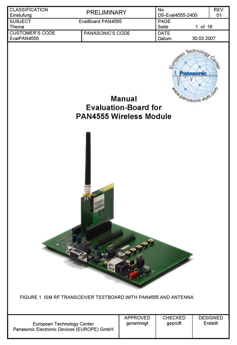
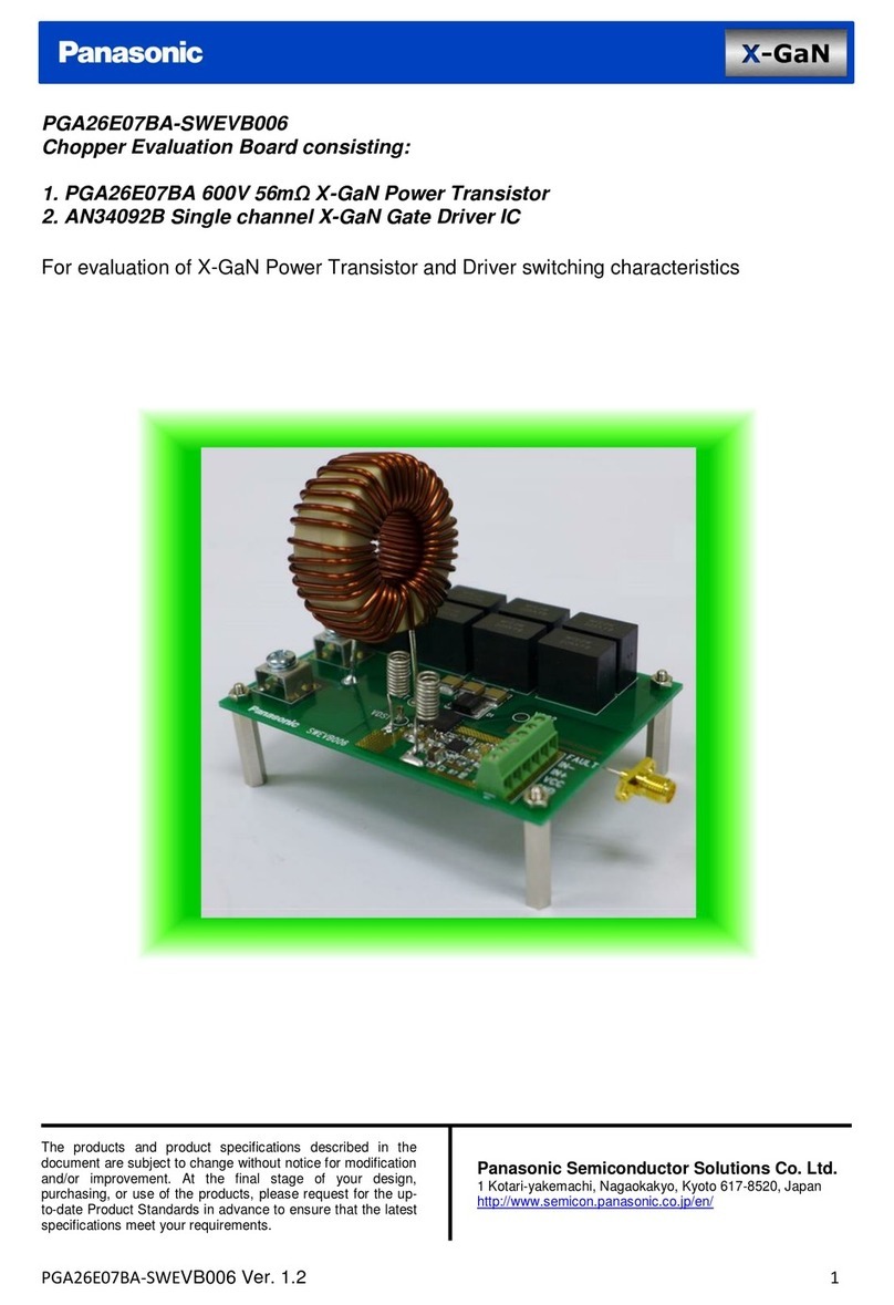
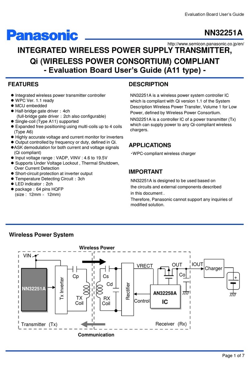
Panasonic PAN9420 User manual

PAN9420
Quick Start Guide
Rev. 1.0
Wireless Modules

PAN9420 Quick Start Guide
Quick Start Guide Rev. 1.0 Page 2
By purchasing any of the products described in this document, the customer accepts the document's
validity and declares their agreement and understanding of its contents and recommendations. Panasonic
Industrial Devices Europe GmbH (Panasonic) reserves the right to make changes as required at any time
without notification.
© Panasonic Industrial Devices Europe GmbH 2018.
All rights reserved.
This Quick Start Guide does not neither implicit nor explicit claim to be complete and free of mistakes.
The information contained herein is presented only as guidance for this Product use. No responsibility,
implicit or explicit is assumed by Panasonic for any infringement of patents or any other intellectual
property rights of third parties that may result from the use of this Product. No license to any intellectual
property right is granted by this document, whether express or implied, by estoppel or otherwise.
Description of hardware, software, and other information in this document is only intended to illustrate the
functionality of the referred Panasonic product. It should not be construed as guaranteeing specific
functionality of the product as described or suitable for a particular application.
Any provided (source) code shall not be used or incorporated into any products or systems whose
manufacture, use or sale is prohibited under any applicable laws or regulations.
Any outlined or referenced (source) code within this document is provided on an “as is” basis without any
right to technical support or updates and without warranty of any kind on a free of charge basis according
to § 516 German Civil Law (BGB) including without limitation, any warranties or conditions of title, non-
infringement, merchantability, or fitness for a particular purpose. Customer acknowledges that
(source) code may bear defects and errors.
The third-party tools mentioned in this document are offered by independent third-party providers who are
solely responsible for these products. Panasonic has no responsibility whatsoever for the performance,
product descriptions, specifications, referenced content, or any and all claims or representations of these
third-party providers. Panasonic makes no warranty whatsoever, neither express nor implied, with respect
to the goods, the referenced contents, or any and all claims or representations of the third-party providers.
To the maximum extent allowable by Law Panasonic assumes no liability whatsoever including without
limitation, indirect, consequential, special, or incidental damages or loss, including without limitation loss of
profits, loss of opportunities, business interruption, and loss of data.
PAN9420 Quick Start Guide
Quick Start Guide Rev. 1.0 Page 3
Table of Contents
1About This Document.........................................................................................................................4
1.1 Purpose and Audience ..............................................................................................................4
1.2 Revision History.........................................................................................................................4
1.3 Use of Symbols .........................................................................................................................4
1.4 Related Documents...................................................................................................................5
2Introduction.........................................................................................................................................6
2.1 What is in the Box......................................................................................................................6
2.2 Additional Equipment.................................................................................................................9
3PAN9420 Overview ...........................................................................................................................10
3.1 Features ..................................................................................................................................10
3.2 Interacting with the Evaluation Kit............................................................................................10
3.3 Powering the Evaluation Kit.....................................................................................................11
4First Time Set Up ..............................................................................................................................14
4.1 Powering..................................................................................................................................14
4.2 Connecting the Evaluation Kit..................................................................................................15
5Navigating the PAN9420 Web Server..............................................................................................22
5.1 Web Server Default Home Page .............................................................................................22
5.2 Web-App Page........................................................................................................................23
6Further Information...........................................................................................................................26
6.1 Contact Us...............................................................................................................................26
6.2 Product Information .................................................................................................................26

PAN9420 Quick Start Guide
Quick Start Guide Rev. 1.0 Page 4
1 About This Document
1.1 Purpose and Audience
The purpose of this document is to allow new users to promptly orient themselves with the
PAN9420 Evaluation Kit, as well as speedily being able to start evaluating and using it.
In this document the PAN9420 Wi-Fi module is synonymously referred to as “PAN9420” or “the
module” and the PAN9420 Evaluation Kit as “Eval Kit” or “the Kit”.
The document is intended for design engineers and application engineers who plan to integrate
the PAN9420 into their product. However, it is generally useful for anyone wanting to
understand the setup of the Evaluation Kit.
1.2 Revision History
Revision
Date
Modifications/Remarks
1.0
15 June 2018
Initial version 1.0
1.3 Use of Symbols
Symbol
Description
Note
Indicates important information for the proper use of the product.
Non-observance can lead to errors.
Attention
Indicates important notes that, if not observed, can put the product’s functionality
at risk.
Tip
Indicates useful information designed to facilitate working with the software.
[chapter number]
[chapter title]
Cross reference
Indicates cross references within the document.
Example:
Description of the symbols used in this document 1.3 Use of Symbols.
Requirement
Indicates a requirement that must be met before the corresponding tasks can be
completed.
Result
Indicates the result of a task or the result of a series of tasks.

PAN9420 Quick Start Guide
Quick Start Guide Rev. 1.0 Page 5
Symbol
Description
This font
GUI text
Indicates fixed terms and text of the graphical user interface.
Example:
Click Save.
Menu > Menu item
Path
Indicates a path, e.g. to access a dialog.
Example:
In the menu, select File > Setup page.
This font
File names, messages, user input
Indicates file names or messages and information displayed on the screen or to
be selected or entered by the user.
Examples:
pan1760.c contains the actual module initialization.
The message Failed to save your data is displayed.
Enter the value Product 123.
[ Key ]
Key
Indicates a key on the keyboard, e.g. [ F10 ].
1.4 Related Documents
[1] Panasonic. PAN9420 Communication Specification Firmware V1.1.X.X
[2] Panasonic. PAN9420 Product Specification
Please refer to the Panasonic website for the most updated and more related documents and
tools.

PAN9420 Quick Start Guide
Quick Start Guide Rev. 1.0 Page 6
2 Introduction
2.1 What is in the Box
The PAN9420 Evaluation Kit comes with the following three components:
The Mother Board (MB)
The PAN9420ETU (Easy To Use) –Mounted on the MB
USB Type-B cable
For any further supportive documentation, please use the QR Code on
the Box or please refer to the link in 6.2 Product Information.

PAN9420 Quick Start Guide
Quick Start Guide Rev. 1.0 Page 7
2.1.1 The Mother Board (MB)
The MB consists of the following features and parts:
Two USB Type-B receptacles
oUSB0: Provides 5V power via USB and the command UART0
oUSB1: Data UART1 (Netcat, Webcat, UDP etc.)
Jumpers
oJP2, JP6 and JP7, Set power source
oJP5 UART0 (RX and TX)
oJP1 UART1 (RX, TX, CTS and RTS)
Switches
oS1: Factory Reset (if held for 10 seconds will invoke)
oS2: Not Connected
oS3: WAKE_UP0
oS4: WAKE_UP1
Optional External 5V power supply via X2 and X3
Figure 1: The Evaluation Kit Motherboard (MB)

PAN9420 Quick Start Guide
Quick Start Guide Rev. 1.0 Page 8
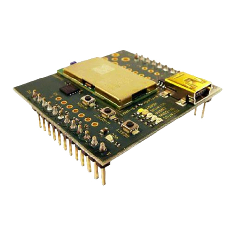
2.1.2 The PAN9420 ETU
The PAN9420ETU is a daughter board with the module mounted on it. It offers access to:
GPIOs, LEDs, U.Fl connector (for external antenna) and an Antenna Selector Switch. Please
see Figure 2: The Evaluation Kit ETU below.
Figure 2: The Evaluation Kit ETU
The ETU comes pre-mounted on the motherboard and can be swapped with other
daughterboards. You can order the ETU by itself.
2.1.3 USB Type-B Cable
The USB Type-B cable is provided to connect the Eval Kit to your PC or Laptop. The cable is
used for data transfer as well as providing the Evaluation Kit with 5V DC, which can be sourced
from your PC or alternatively from an external power source such as a portable power bank.
Figure 3: USB Type-B Cable

PAN9420 Quick Start Guide
Quick Start Guide Rev. 1.0 Page 9
2.2 Additional Equipment
To interact with the PAN9420 Evaluation Kit, you will also need:
A Desktop or Laptop (PC) with a USB port, and the following Software Tools:
oA Browser such as: Chrome, Firefox, etc.
oA Terminal such as: PuTTY, TeraTerm, HTerm, etc.
oPanasonic’s WIFIgurator - An integrated SW tool for the PAN9420 Eval Kit.
Alternatively, you can use a smart device such as a smartphone or a tablet.
Using a smart device will limit you to an OTA (Over The Air) wireless
connectivity as described in 3.2.2 Wireless.
For the most comprehensive evaluation capabilities, you will need to use a PC.
2.2.1 The WIFIgurator
The WIFIgurator is a handy evaluation tool for Windows OS only, provided by Panasonic.
To use the WIFIgurator, please follow the next steps:
1. Download the ZIP file from the download section.
Europe:
https://pideu.panasonic.de/products/wireless-modules/wifi/PAN9420-Fully-Embedded-
Stand-Alone-Wi-Fi-Module.html
North America:
https://na.industrial.panasonic.com/products/wireless-connectivity/wi-fi-
modules/embedded-wi-fi
2. Extract the ZIP file.
3. Run WIFIgurator.exe from the extracted directory (see Figure 4 below).
Figure 4: WIFIgurator Directory

PAN9420 Quick Start Guide
Quick Start Guide Rev. 1.0 Page 10
3 PAN9420 Overview
3.1 Features
The PAN9420 is an all-inclusive, embedded Wi-Fi module. It contains an integrated IoT-ready
web-stack that offers and provides many key IoT features.
For detailed and up-to-date list and description of all available features, please read the
PAN9420 Communication Specification available in the download section on our
website:
Europe:
https://pideu.panasonic.de/products/wireless-modules/wifi/PAN9420-Fully-Embedded-Stand-
Alone-Wi-Fi-Module.html
North America:
https://na.industrial.panasonic.com/products/wireless-connectivity/wi-fi-modules/embedded-wi-fi
3.2 Interacting with the Evaluation Kit
The PAN9420 Eval Kit is an evaluation and design platform for the PAN9420 Module. There are
two optional methods to interact with the PAN9420 using the Evaluation Kit:
3.2.1 Wired
This method uses the provided USB ports with USB0 for commands and USB1 for data. Using
this scheme, you will also need to use the Terminal program and the WIFIgurator. You will be
able to:
Interact with the various SW modules provided by the integrated stack
oIssue commands
oReceive acknowledgment (and Error codes)
Stream data
Upload new:
oWeb server content
oServer and Client certificates
oClient private keys
oConfiguration files
3.2.2 Wireless
This method is using the Wi-Fi connection and allows the user to access the web server, and
interact with its content. You can still interact with the stack, given that the webserver provides a
command interface to the stack.
Please note that the two methods are distinct, and complementary to each other, yet, they
share some limited overlapped functionality.

PAN9420 Quick Start Guide
Quick Start Guide Rev. 1.0 Page 11
3.3 Powering the Evaluation Kit
3.3.1 General
To power up the evaluation kit, please choose between the following two methods
1. External Power
Use X2 and X3 to provide 5V power from an external source. An external source can be
a battery or a Power Supply. This method allows users to perform some power
measurements.
The power provided to the board must be 5V DC.
2. USB connection
a. Connect the MB’s USB0 Port to your Computer’s USB-Port.
b. Alternatively, a portable power-bank which provides 5V can be used to power
up the Eval Kit.
Using USB0 to power up the Eval Kit is the recommended method.
On the PAN9420 Evaluation Kit:
USB0 is connected to the PAN9420’s UART0.
UART0 is primarily utilized to send commands to, and receive
acknowledgments between the PAN9420 and the Host.
USB1 is connected to the PAN9420’s UART1.
UART1 is employed by the following SW Modules to stream data:
oNetcat
oWebcat
oUDP
oHTTP client
oMQTT client
oFirmware update
oCMD to BIN UART tunneling

PAN9420 Quick Start Guide
Quick Start Guide Rev. 1.0 Page 12
3.3.2 Proper Jumpers Setup
Prior to applying power to the evaluation kit, please make sure that all the
jumpers on the Motherboard are set properly.
In the picture below (circled in Red) are all related jumpers.
Figure 5: MB Jumpers Location
Please refer to Figure 5 above, as well to the pictures provided below.
Powering the kit using USB0:
JP4 Pin 1 connected to Pin 2
JP6 Pin 1 connected to Pin 2
JP7 connected
Powering the kit using X2 and X3:
JP4Pin 2 connected to Pin 3
JP6 Pin 1 connected to Pin 2
JP7 connected

PAN9420 Quick Start Guide
Quick Start Guide Rev. 1.0 Page 13
UART0 Jumpers:
JP5 1 connected across
2 connected across
UART1 Jumpers:
JP1 1 connected across
2 connected across
3 connected across
4 connected across

PAN9420 Quick Start Guide
Quick Start Guide Rev. 1.0 Page 14
4 First Time Set Up
4.1 Powering
As mentioned above, to connect to and communicate with the Evaluation Kit and the PAN9420,
you will need a PC with your choice of OS. Additionally, you will need the following tools to be
installed on it:
A browser
A Terminal program to send and receive datagrams
Alternatively, or additionally to the Terminal you will need the WIFIgurator
Please choose your preferred powering method as per 3.3 Powering the Evaluation Kit
above.
Once power is applied, the Eval Kit will power on and go through initialization. The boot and
initialization takes a few seconds.
The subsequent LEDs on the ETU will light up as follows:
1. VCC Constantly on
2. READY Constantly on
3. MSTATUS Blinking
WSTATUS might be blinking periodically, which indicates the modules
scanning process.
Please see below illustration of the LED position:
Figure 6: ETU LED position

PAN9420 Quick Start Guide
Quick Start Guide Rev. 1.0 Page 15
4.2 Connecting the Evaluation Kit
As mentioned above in 3.2 Interacting with the Evaluation Kit there are two optional methods
to connect and interact with the PAN9420, please choose your preferred method, and use the
following to interact with the PAN9420.
4.2.1 Wired –Connecting through USB0 and a Terminal Program
Simply connect the provided USB Type-B cable to USB0 of the MB and to a port in your
computer.
In the very first time connecting the USB0 of the MB to your PC, and given
that the FTDI driver is NOT pre-installed on your machine, you will be asked to
install the FTDI drivers.
After successfully installing the FTDI driver, your PC will enumerate two virtual COM ports. One
is for JTAG-via-USB (mostly it is the lowest COM number of the two) and the other one is
connected to PAN9420’s UART0 (mostly it is the highest COM number of the two).
On a Windows machine, use the device manager to discern which COM number corresponds to
UART0. After connecting the evaluation kit to your PC, in device manager > ports, you should
see two COM ports (see below). Generally, the port with the highest number of the two
corresponds with UART0. In the example below, you will use COM19.
Figure 7: Device Manager and virtual COM ports
To test the Command Interface via USB0 you could use any terminal program, Panasonic’s
terminal program of choice is HTerm.

PAN9420 Quick Start Guide
Quick Start Guide Rev. 1.0 Page 16
Default configuration for UART0 and UART1:
Baud rate: 115200
Data bits: 8
Parity bit: none
Stop bits: 1
UART0 does not utilize any flow control.
UART1 utilizes HW flow control (RTS/CTS). To achieve maximal throughput,
flow control for UART1 is required.
If successfully connected, try to send the command get system firmware using your
Terminal Program of choice, to request the firmware version of the module.
A command MUST BE followed by CR (Carriage Return) and LF (Line Feed)
as described in the communication specification. You can set your terminal to
issue them automatically.
You might also need to set the terminal’s echo.
If you did not use HTerm before, please note:
If you are new to HTerm, please do not use the ASend button.
To invoke a command in Hterm –
Type it in
Press [Enter] on your keyboard
Figure 8: Invoking a command in HTerm

PAN9420 Quick Start Guide
Quick Start Guide Rev. 1.0 Page 17
The response from the PAN9420 should be received like in the received window of the HTerm-
based example below:
Figure 9: Terminal Set Up and Response

PAN9420 Quick Start Guide
Quick Start Guide Rev. 1.0 Page 18
4.2.2 Wired –Connecting through USB0 and the WIFIgurator
An alternative to using a Terminal Program is using the WIFIgurator provided by Panasonic.
The WIFIgurator incorporates Terminal like capabilities, along with an easy-to-use GUI.
As in 4.2.1 Wired –Connecting through USB0 and a Terminal Program, connect the MB’s
USB0 to your PC’s USB port using the provided USB Type-B cable.
From the WIFIgurator’s directory (see 2.2 Additional Equipment), double-click the executable
WIFIgurator.exe.
Figure 10: WIFIgurator Directory
You will see the WIFIgurator’s GUI along with the Welcome Page.
Figure 11: WIFIgurator Welcome

PAN9420 Quick Start Guide
Quick Start Guide Rev. 1.0 Page 19
To start the program, read the general Terms and Conditions, then click on the Accept and
Start button. In order to read out the modules firmware, MAC address, serial number, radio
version, bootloader version and hardware revision, perform the following steps:
1. On the top, choose the corresponding COM port. It is the same as used in 4.2.1
Wired –Connecting through USB0 and a Terminal Program.
2. Click the Connect button.
Figure 12: WIFIgurator connection
3. Lastly click on the Read Out button.
4. You should see a response in the Communication part of the GUI:
Figure 13: WIFIgurator Reading Info

PAN9420 Quick Start Guide
Quick Start Guide Rev. 1.0 Page 20
Using the WIFIgurator you will be able to
Issue commands and see the response
Easily and using the GUI, set major key features
Convert your HTML code to a firmware update file (.fwu)
Load the firmware onto the module
4.2.3 Wireless –Connecting through Wi-Fi
To connect to the PAN9420 through Wi-Fi, all you need to do, is to apply power to the
Evaluation Kit (see 3.3 Powering the Evaluation Kit).
Once the board is powered and initialized, activate the WLAN Network Manager on your PC or
Smart Device.
In Windows based machines, it is mostly on the bottom right corner of the screen.
Your device will scan for new wireless Access Points (APs):
Look for the SSID PAN9420_AP.
Connect to PAN9420_AP.
The standard connection is protected with a WPA2 key. When prompted to enter a
password, please enter the default password: PAN_9420.
Figure 14: Wi-Fi connection
Other manuals for PAN9420
2
Table of contents
Other Panasonic Motherboard manuals

Panasonic
Panasonic PAN4570 User manual

Panasonic
Panasonic NN32251A User manual

Panasonic
Panasonic PAN9320ETU User manual

Panasonic
Panasonic PAN9520 User manual

Panasonic
Panasonic Grid-EYE User manual

Panasonic
Panasonic Grid-EYE User manual

Panasonic
Panasonic AN33014UA User manual

Panasonic
Panasonic NN30320A User manual

Panasonic
Panasonic EVB-NN30312A User manual

Panasonic
Panasonic AN30182A-EVB User manual