Panasonic PAN9520 User manual

Wireless Connectivity
PAN9520 ETU
EasyToUse Evaluation Tool
User Guide
Rev. 1.0

PAN9520 ETU Evaluation Tool
User Guide Rev. 1.0 Page 2 of 35
Overview
The PAN9520 ETU is an evaluation board for the
PAN9520 embedded Wi-Fi module based on the
Espressif®ESP32-S2.
PAN9520 Features
•Embedded 2.4 GHz Wi-Fi 802.11 b/g/n module
•Xtensa®single-core 32-bit LX7 microprocessor,
up to 240 MHz
•Chip internal 128 kB ROM, 320 kB SRAM, and
16 kB low power SRAM
•Integrated QSPI Flash and PSRAM (a variety of
memory densities are available)
•Ultra-Low Power (ULP) co-processor usable in
deep sleep mode
•All security features required for WPA2 and
WPA3 personal
•Espressif IoT Development Framework (ESP-IDF)
with a multitude of examples available for
software development
•Supports 20 MHz and 40 MHz bandwidths in
2.4 GHz band with data rates up to 150 Mbps
•Simultaneous support for Infrastructure Station,
SoftAP, and promiscuous modes
•802.11mc Fine Time Measurement (FTM)
•36× programmable GPIOs with a rich set of
alternative functionalities
PAN9520 Characteristics
•Surface Mount Type (SMT):
24 mm × 13 mm × 3.1 mm
•Tx power: up to 19.5 dBm at IEEE 802.11b
1 Mbps
•Rx sensitivity: of -97 dBm at IEEE 802.11b 1 Mbps
•Power supply: 3 V to 3.6 V
•Current consumption: 260 mA Tx (average at 11b,
11 Mbps), 76 mA Rx (40 MHz channel), 310 mA Tx
peak
•Deep sleep mode: <100 µA typical power
consumption (RTC timer only and VDD_SPI
disconnected)
•Wide temperature range from -40 °C to 85 °C
Evaluation Tool Features
•Arduino Interface configurable as shield or board
•All GPIO break out
•FTDI FT2232 USB to dual interface
–USB to JTAG
–USB to UART0
•FTDI FT232 USB to UART1 interface
•Peripherals are deactivatable for low power
applications
•4× user Buttons, 3× user LEDs
•Module native USB interface
•Camera interface
•Contains module variant ENW49D01A1KF with
4 MB of QSPI Flash and 2 MB of QSPI PSRAM
Block Diagram
User Interfaces
Buttons
LEDs
USB HUB
FT232
USB to UART1
FT2232
USB to JTAG
USB to UART0
Current
Measurement
Arduino
Interface GPIO Breakout Camera
Interface
PAN9520
PAN9520 ETU
Easy-To-Use Evaluation Board
USB
Module Native
USB
Debugging/UART
Current Measurement
Connector
Arduino
Pin Header
Breakout Pin
Headers
Camera
Connector

PAN9520 ETU Evaluation Tool
User Guide Rev. 1.0 Page 3 of 35
By purchase of any of the products described in this document the customer accepts the document's
validity and declares their agreement and understanding of its contents and recommendations. Panasonic
Industrial Devices Europe GmbH (Panasonic) reserves the right to make changes as required at any time
without notification.
© Panasonic Industrial Devices Europe GmbH 2021.
This document is copyrighted. Reproduction of this document is permissible only if reproduction is without
alteration and is accompanied by all associated warranties, conditions, limitations, and notices. Do not
disclose it to a third party.
All rights reserved.
This User Guide does not lodge the claim to be complete and free of mistakes.
The information contained herein is presented only as guidance for Product use. No responsibility is
assumed by Panasonic for any infringement of patents or any other intellectual property rights of third
parties that may result from the use of Product. No license to any intellectual property right is granted by
this document, whether express or implied, by estoppel or otherwise.
Description of hardware, software, and other information in this document is only intended to illustrate the
functionality of the referred Panasonic product. It should not be construed as guaranteeing specific
functionality of the product as described or suitable for a particular application.
Any provided (source) code shall not be used or incorporated into any products or systems whose
manufacture, use or sale is prohibited under any applicable laws or regulations.
Any outlined or referenced (source) code within this document is provided on an “as is” basis without any
right to technical support or updates and without warranty of any kind on a free of charge basis according
to § 516 German Civil Law (BGB) including without limitation, any warranties or conditions of title, non
infringement, merchantability, or fitness for a particular purpose. Customer acknowledges that (source)
code may bear defects and errors.
The third party tools mentioned in this document are offered by independent third party providers who are
solely responsible for these products. Panasonic has no responsibility whatsoever for the performance,
product descriptions, specifications, referenced content, or any and all claims or representations of these
third party providers. Panasonic makes no warranty whatsoever, neither express nor implied, with respect
to the goods, the referenced contents, or any and all claims or representations of the third party providers.
To the maximum extent allowable by Law Panasonic assumes no liability whatsoever including without
limitation, indirect, consequential, special, or incidental damages or loss, including without limitation loss of
profits, loss of opportunities, business interruption, and loss of data.
PAN9520 ETU Evaluation Tool
User Guide Rev. 1.0 Page 4 of 35
Table of Contents
1About This Document.........................................................................................................................5
1.1 Purpose and Audience ..............................................................................................................5
1.2 Revision History.........................................................................................................................5
1.3 Use of Symbols .........................................................................................................................5
1.4 Related Documents...................................................................................................................6
2Overview..............................................................................................................................................7
3PAN9520 ETU......................................................................................................................................8
3.1 Block Diagram...........................................................................................................................8
3.2 Board Overview.........................................................................................................................8
3.3 Powering Options ....................................................................................................................11
3.4 Default Boot Mode...................................................................................................................13
3.5 Breakout Pin Header ...............................................................................................................14
3.6 User LEDs...............................................................................................................................16
3.7 User Buttons............................................................................................................................16
3.8 Arduino Interface .....................................................................................................................17
3.9 Arduino Board/Shield Configuration ........................................................................................19
3.10 Current Measurement..............................................................................................................20
3.11 USB-IO Switch.........................................................................................................................21
3.12 I²C Pull-Up Resistors...............................................................................................................21
3.13 Camera Interface.....................................................................................................................22
3.14 Disabling Peripherals...............................................................................................................26
3.15 PAN9520 RF Switch (SPDT) Control.......................................................................................27
3.16 Overview: Interfaces’ Pin Assignment .....................................................................................28
3.17 Software Development ............................................................................................................29
4Contact Details..................................................................................................................................35
4.1 Contact Us...............................................................................................................................35
4.2 Product Information .................................................................................................................35

PAN9520 ETU Evaluation Tool 1 About This Document
User Guide Rev. 1.0 Page 5 of 35
1 About This Document
1.1 Purpose and Audience
This User Guide is intended to give a detailed description of the Easy-To-Use (ETU) evaluation
board components and functionalities.
It is intended for hardware design, application, and Original Equipment Manufacturers (OEM)
engineers.
The product is referred to as “the PAN9520 ETU” or “the ETU” within this document.
1.2 Revision History
Revision
Date
Modifications/Remarks
1.0
2021-06-21
First version
1.3 Use of Symbols
Symbol
Description
Note
Indicates important information for the proper use of the product.
Non-observance can lead to errors.
Attention
Indicates important notes that, if not observed, can put the product’s functionality
at risk.
Tip
Indicates useful information designed to facilitate working with the module and
software.
[chapter number]
[chapter title]
Cross reference
Indicates cross references within the document.
Example:
Description of the symbols used in this document 1.3 Use of Symbols.
✓
Requirement
Indicates a requirement that must be met before the corresponding tasks can be
completed.
➔
Result
Indicates the result of a task or the result of a series of tasks.
This font
GUI text
Indicates fixed terms and text of the graphical user interface.
Example:
Click Save.
Other manuals for PAN9520
1
Table of contents
Other Panasonic Motherboard manuals

Panasonic
Panasonic AN30182A-EVB User manual

Panasonic
Panasonic PGA26E07BA-SWEVB006 User manual

Panasonic
Panasonic Grid-EYE User manual

Panasonic
Panasonic NN32251A User manual

Panasonic
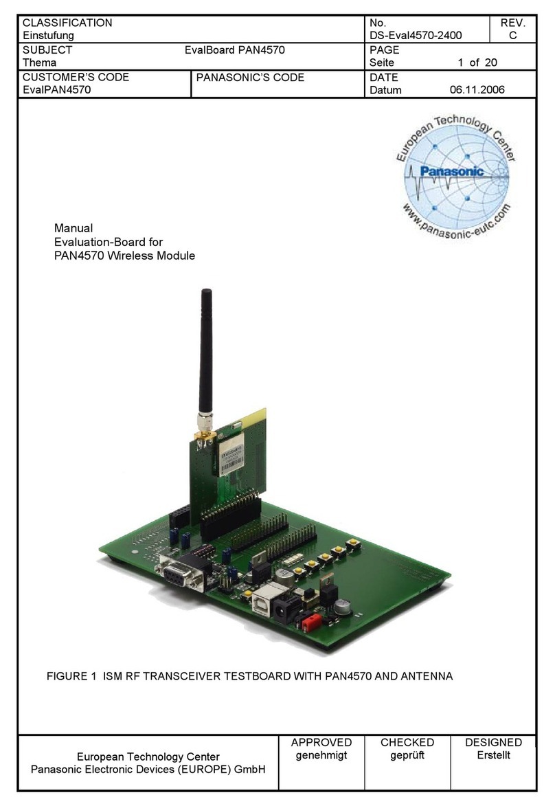
Panasonic PAN4570 User manual

Panasonic
Panasonic AN33014UA User manual

Panasonic
Panasonic PAN9420 User manual

Panasonic
Panasonic PAN9320ETU User manual

Panasonic
Panasonic Grid-EYE User manual

Panasonic
Panasonic EVB-NN30312A User manual