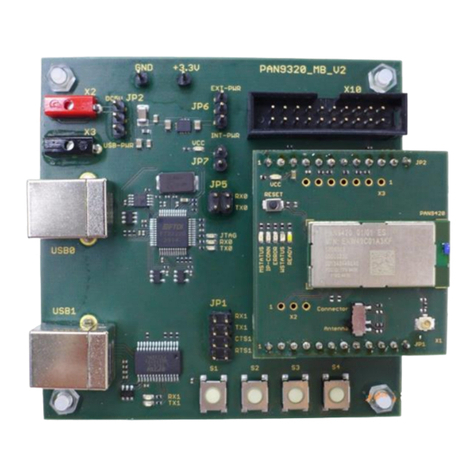
Panasonic PAN1311/21 USB User manual

No.
DS-PAN1311/21USB
REV.
1.1
PAGE
1 of 11
Quick Start Guide
Evaluation Board (EVB) PAN1311/21 USB
DATE
15.09.2011
PANASONIC ELECTRONIC DEVICES EUROPE
GmbH
DESIGNED
Erstellt
IW
Quick Start Guide
Evaluation Board (EVB) PAN1311/21 USB

No.
DS-PAN1311/21USB
REV.
1.1
PAGE
2 of 11
Quick Start Guide
Evaluation Board (EVB) PAN1311/21 USB
DATE
15.09.2011
PANASONIC ELECTRONIC DEVICES EUROPE
GmbH
DESIGNED
Erstellt
IW
1. CONTENT
1. Content...................................................................................................................................2
2. Introduction ............................................................................................................................3
2.1 Related documents...............................................................................................................3
4. Functional overview................................................................................................................3
5. Connection setup ...................................................................................................................4
5.1 Software start and navigation ...............................................................................................4
5.2 Port configuration .................................................................................................................5
5.3 Firmware handling................................................................................................................6
5.4 Command tab navigation......................................................................................................7
5.5 Creating a connection...........................................................................................................8
6. Schematic ..............................................................................................................................9
7. Document Information ..........................................................................................................10
8. General Information..............................................................................................................11
8.1 Waiver................................................................................................................................11
9. Life Support Policy ...............................................................................................................11

No.
DS-PAN1311/21USB
REV.
1.1
PAGE
3 of 11
Quick Start Guide
Evaluation Board (EVB) PAN1311/21 USB
DATE
15.09.2011
PANASONIC ELECTRONIC DEVICES EUROPE
GmbH
DESIGNED
Erstellt
IW
2. INTRODUCTION
This document should provide the minimum knowledge needed to establish a simple
connection between two PAN1321ETU USB Evaluation Boards (EVB) using Infineon
eBMU_SPP_Toolbox software. For this limited information is granted. To learn about all
aspects of the software please refer to the related documents listed below.
2.1 RELATED DOCUMENTS
For further information on Infineon eBMU_SPP_Toolbox software and it’s implemented AT
command set please refer to:
•PAN13x1_ReleaseNote_SPP_AT_SW08_V1.8_RN_Rev1.0_DRAFT
•PAN13x1_ReleaseNote_SPP_AT_SW21_V2.1_RN_Rev1.0_DRAFT -iPhone version
•PAN13x1_SPP_AT_UserManual_SoftwareDescription_Rev5.0 DRAFT
•PAN1321_AN_DesignGuide_Rev2 1
•User's_Manual_PAN1311_V20.xx_Rev1.1
•User's_Manual_PAN1321_V20.xx_Rev3.1
4. FUNCTIONAL OVERVIEW
The figure below shows an overview of the Evaluation Board. If there is the need to connect
your µController to the EVB please de-solder R1, R2, R3, R4.
For more details please refer also to the schematic in chapter Schematic.
Figure 2 : Evaluation Board Overview
Hardware
Reset
UART to USB
Converter Section
For interfaces
description refer to
schematic
Power Supply
section

No.
DS-PAN1311/21USB
REV.
1.1
PAGE
4 of 11
Quick Start Guide
Evaluation Board (EVB) PAN1311/21 USB
DATE
15.09.2011
PANASONIC ELECTRONIC DEVICES EUROPE
GmbH
DESIGNED
Erstellt
IW
5. CONNECTION SETUP
This chapter describes how to use the eBMU_SPP_Toolbox software in order to send simple
data packages from one EVB to the other.
5.1 SOFTWARE START AND NAVIGATION
Browse to the folder where the eBMU_SPP_Toolbox.exe file is located and start it. The user
interface (figure 2) is shown.
Figure 4 : Toolbox start up screen

No.
DS-PAN1311/21USB
REV.
1.1
PAGE
5 of 11
Quick Start Guide
Evaluation Board (EVB) PAN1311/21 USB
DATE
15.09.2011
PANASONIC ELECTRONIC DEVICES EUROPE
GmbH
DESIGNED
Erstellt
IW
5.2 PORT CONFIGURATION
Please note that the eBMU Toolbox can handle only COM port numbers below 10. You can
configure in the System Hardware settings in your operating system. The USB driver can be
found in the installation folder.
On the settings tab the communication via COM port is handled. It is possible to set a
number of default parameters for both EVBs and to save/load all the changes made to this
page (saving the settings will also make the program remember the selected port numbers).
Please select the right port numbers for both EVBs (found at Windows OS: control panel
system hardware device manager Ports (COM & LPT)) and click the buttons
open/close 1 & open/close 2. A status message should appear below the text fields (figure
3). Leave the rest unchanged for now.
Figure 5 : COM port setup

No.
DS-PAN1311/21USB
REV.
1.1
PAGE
6 of 11
Quick Start Guide
Evaluation Board (EVB) PAN1311/21 USB
DATE
15.09.2011
PANASONIC ELECTRONIC DEVICES EUROPE
GmbH
DESIGNED
Erstellt
IW
5.3 FIRMWARE HANDLING
At the testing tab firmware can be downloaded (Download image) to the EVB and a number
of changes can be made to it (Change BD-data) like assigning a unique BT address (e.g.
0003199E8B73) and oscillator trim value. Make sure that the Production mode is enabled
before any of these buttons on this tab are used. To do this mark On and confirm with a click
on Production mode. The text field should inform you about of success of this procedure. Be
advised to do a hardware reset (push button on EVB) after all changes were made.
Please note:
The BD_Address and OSC_Trim value have to be read out by “Read BD Address” command
before downloading. They have to be programmed by “Change BD-data” command after
writing the new image.
Figure 6 : Testing tab

No.
DS-PAN1311/21USB
REV.
1.1
PAGE
7 of 11
Quick Start Guide
Evaluation Board (EVB) PAN1311/21 USB
DATE
15.09.2011
PANASONIC ELECTRONIC DEVICES EUROPE
GmbH
DESIGNED
Erstellt
IW
5.4 COMMAND TAB NAVIGATION
At the Commands tab are several commands listed for easy click-and-use. Note the colour
coding identifying commands by their intended usage:
•Yellow: Settings and informational commands.
•Pink: Security related commands.
•Green: Connection related.
•Red: Disconnection commands.
•Blue: Data transfer
•Light blue: Accept connection
•White: Sniff (during connection)
Figure 7 : Command tab and used commands
For simple data transfer find the needed commands marked in figure 5. The Custom
Command button can be used to issue any command of the command set (refer to
PMB8753-2_SPP_AT_specification_R1.pdf).

No.
DS-PAN1311/21USB
REV.
1.1
PAGE
8 of 11
Quick Start Guide
Evaluation Board (EVB) PAN1311/21 USB
DATE
15.09.2011
PANASONIC ELECTRONIC DEVICES EUROPE
GmbH
DESIGNED
Erstellt
IW
5.5 CREATING A CONNECTION
To send data from one EVB to the other one of them must be prepared for connection, while
the other will request a connection. Follow these steps:
1. Click on Make Discoverable on Device A. Choose option 3: Inquiry_Page Scan
enabled. The text field should state the issued command sent (arrow) and the OK
response (arrow). Now device A can be found by other devices by both available
scan methods.
2. Click on Register Local Service. There are some options to change identification of
the new service but the default values are ok. Simply choose Send. This service now
can be found by other devices of the network.
3. Click the Auto Accept Connection Requests command and choose option 1. EVB A
will auto accept connection requests from now on. Device A is now ready for
connection!
4. Get the address of EVB A with the help of Read BD Address. In the text field you will
find the desired information (e.g. “[…] <-- +RRBDRES=0003199E8B73, […]”). With
this Device A can be addressed when…
5. …issuing Connection Request from Device B. Type or copy the BD address of
Device A into the BD Address 0x text field. Name the service channel under which
the service of Device A was registered in step 2. If no changes were in step 2 service
channel 01 should do. Click send. After a short while both Devices should state
connected.
6. Done! Now data strings can be sent from one EVB to the other with the Send Data
command. Data send and received will be displayed in the text fields. Another click
on Send Data will close its dialog box.
Your text fields should look like Figure 6 or alike after step 1 to 5 were made. If problems or
errors are encountered feel free to hardware reset (EVB push button) both boards and start
over with step 1.
Figure 8 : text field output from step 1 to 6
No.
DS-PAN1311/21USB
REV.
1.1
PAGE
9 of 11
Quick Start Guide
Evaluation Board (EVB) PAN1311/21 USB
DATE
15.09.2011
PANASONIC ELECTRONIC DEVICES EUROPE
GmbH
DESIGNED
Erstellt
IW
6. SCHEMATIC

No.
DS-PAN1311/21USB
REV.
1.1
PAGE
10 of 11
Quick Start Guide
Evaluation Board (EVB) PAN1311/21 USB
DATE
15.09.2011
PANASONIC ELECTRONIC DEVICES EUROPE
GmbH
DESIGNED
Erstellt
IW
7. DOCUMENT INFORMATION
Revision
Version
Date
Datum
Modification / Remarks
Änderungen / Bemerkungen
1.0 18.04.2011 Initial version
1.1 15.09.2011 Updated documentation information in chapter 2.1
Table 3 : Document version

No.
DS-PAN1311/21USB
REV.
1.1
PAGE
11 of 11
Quick Start Guide
Evaluation Board (EVB) PAN1311/21 USB
DATE
15.09.2011
PANASONIC ELECTRONIC DEVICES EUROPE
GmbH
DESIGNED
Erstellt
IW
8. GENERAL INFORMATION
© Panasonic Electronic Devices Europe GmbH 2011.
All rights reserved.
This product description does not lodge the claim to be complete and free of mistakes.
Please contact the related product manager in every case.
If we deliver samples to the customer, these samples have the status Engineering
Samples. This means, the design of this product is not yet concluded. Engineering
Samples may be partially or fully functional, and there may be differences to be published
Data Sheet.
Engineering Samples are not qualified and are not to be used for reliability testing or
series production.
8.1 WAIVER
Customer acknowledges that samples may deviate from the Data Sheet and may bear
defects due to their status of development and the lack of qualification mentioned above.
Panasonic rejects any liability or product warranty for Engineering Samples. In particular,
Panasonic waives liability for damages caused by
•the use of the Engineering Sample other than for Evaluation Purposes, particularly
the installation or integration in an other product to be sold by Customer,
•deviation or lapse in function of Engineering Sample,
•improper use of Engineering Samples.
Panasonic waives any liability for consequential and incidental damages.
In case of any questions, please contact your local sales partner or the related product
manager.
9. LIFE SUPPORT POLICY
This Panasonic product is not designed for use in life support appliances, devices, or
systems where malfunction can reasonably be expected to result in a significant personal
injury to the user, or as a critical component in any life support device or system whose
failure to perform can be reasonably expected to cause the failure of the life support
device or system, or to affect its safety or effectiveness. Panasonic customers using or
selling these products for use in such applications do so at their own risk and agree to fully
indemnify Panasonic for any damages resulting.
Table of contents
Other Panasonic Motherboard manuals

Panasonic
Panasonic PGA26E07BA-SWEVB008 User manual

Panasonic
Panasonic Grid-EYE User manual

Panasonic
Panasonic PAN9320ETU User manual

Panasonic
Panasonic EVB-NN30312A User manual

Panasonic
Panasonic EvalBoard PAN4555 User manual

Panasonic
Panasonic PAN9420 User manual

Panasonic
Panasonic NN32251A User manual

Panasonic
Panasonic NN30320A User manual

Panasonic
Panasonic AN33014UA User manual

Panasonic
Panasonic AN30182A-EVB User manual