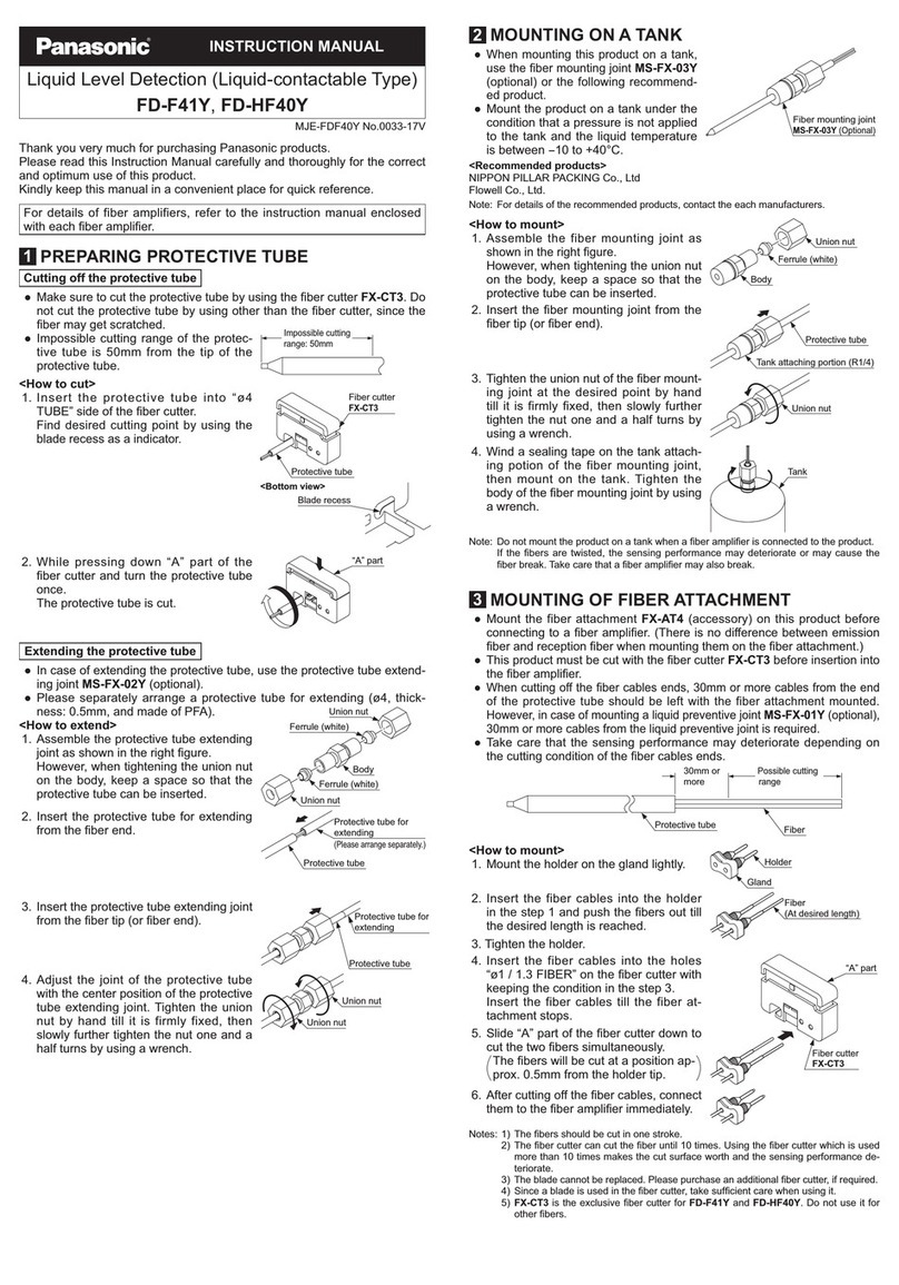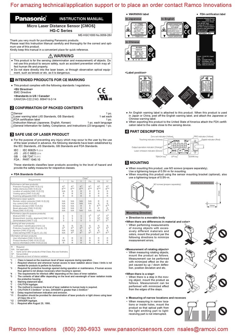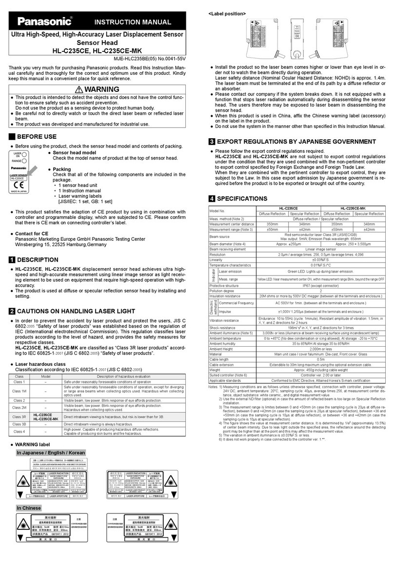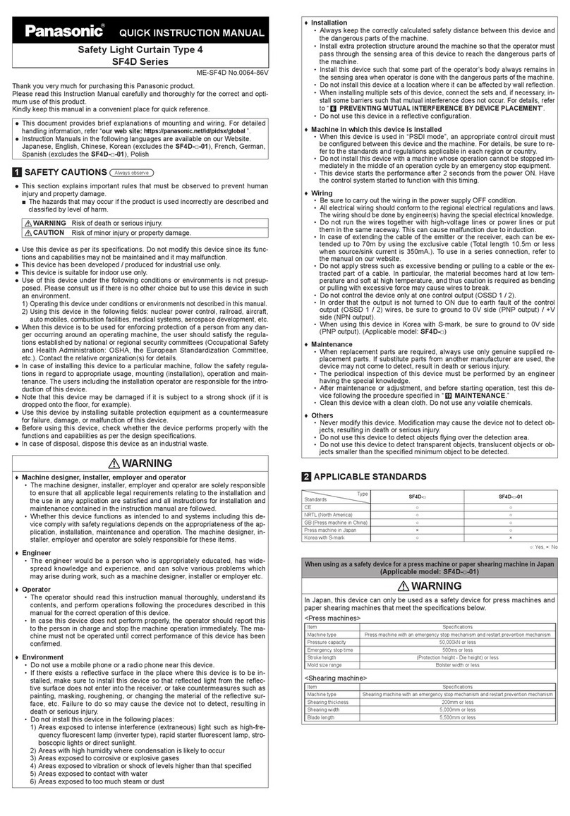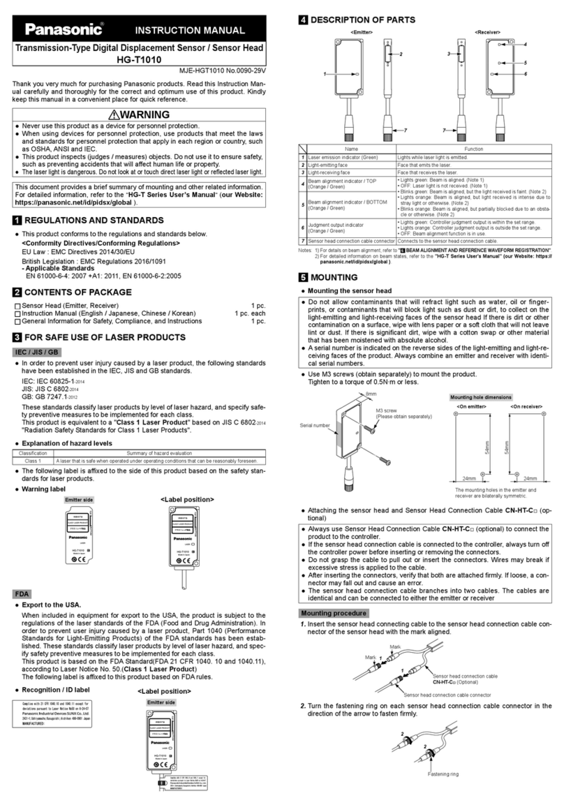
INSTRUCTION MANUAL
Transmission-Type Digital Displacement Sensor / Sensor Head
HG-T1110
MJE-HGT1110 No.0090-31V
Thank you very much for purchasing Panasonic products. Read this Instruction Man-
ual carefully and thoroughly for the correct and optimum use of this product. Kindly
keep this manual in a convenient place for quick reference.
WARNING
●Never use this product as a device for personnel protection.
●When using devices for personnel protection, use products that meet the laws
and standards for personnel protection that apply in each region or country, such
as OSHA, ANSI and IEC.
●This product inspects (judges / measures) objects. Do not use it to ensure safety,
such as preventing accidents that will aect human life or property.
●The laser light is dangerous. Do not look at or touch direct laser light or reected laser light.
This document provides a brief summary of mounting and other related information.
For detailed information, refer to the
“
HG-T Series User’s Manual
”
(our Website:
https://panasonic.net/id/pidsx/global ).
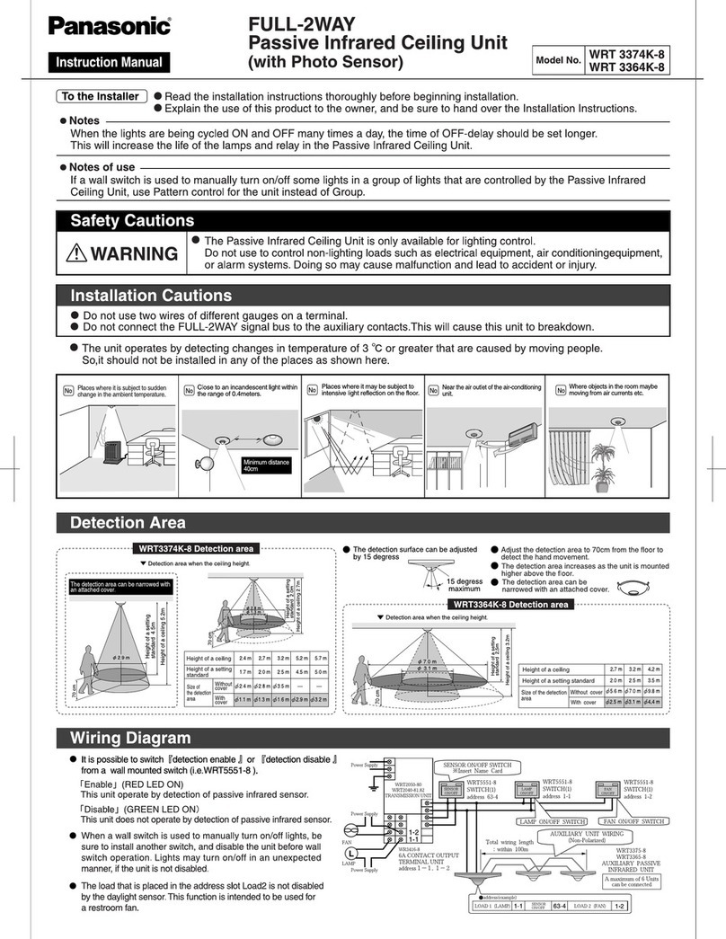
1REGULATIONS AND STANDARDS
●This product conforms to the regulations and standards below.
<Conformity Directives/Conforming Regulations>
EU Law : EMC Directives 2014/30/EU
British Legislation : EMC Regulations 2016/1091
- Applicable Standards
EN 61000-6-4: 2007 +A1: 2011, EN 61000-6-2:2005
2CONTENTS OF PACKAGE
Sensor Head (Emitter, Receiver) 1 pc.
Instruction Manual (English / Japanese, Chinese / Korean) 1 pc. each
General Information for Safety, Compliance, and Instructions 1 pc.
3FOR SAFE USE OF LASER PRODUCTS
IEC / JIS / GB
●In order to prevent user injury caused by a laser product, the following standards
have been established in the IEC, JIS and GB standards.
IEC: IEC 60825-1-2014
JIS: JIS C 6802-2014
GB: GB 7247.1-2012
These standards classify laser products by level of laser hazard, and specify safe-
ty preventive measures to be implemented for each class.
This product is equivalent to a "Class 1 Laser Product" based on JIS C 6802-2014
"Radiation Safety Standards for Class 1 Laser Products".
●Explanation of hazard levels
Classication Summary of hazard evaluation
Class 1 A laser that is safe when operated under operating conditions that can be reasonably foreseen.
● The following label is axed to the side of this product based on the safety stan-
dards for laser products.
●Warning label
Emitter side <Label position>
FDA
●Export to the USA.
When included in equipment for export to the USA, the product is subject to the
regulations of the laser standards of the FDA (Food and Drug Administration). In
order to prevent user injury caused by a laser product, Part 1040 (Performance
Standards for Light-Emitting Products) of the FDA standards has been estab-
lished. These standards classify laser products by level of laser hazard, and spec-
ify safety preventive measures to be implemented for each class.
This product is based on the FDA Standard(FDA 21 CFR 1040. 10 and 1040.11),
according to Laser Notice No. 50.(Class 1 Laser Product)
The following label is axed to this product based on FDA rules.
<Label position>
●Recognition / ID label
Emitter side
4DESCRIPTION OF PARTS
<Emitter>
1
2
5
<Receiver>
3
5
4
Name Function
1Laser emission indicator (Green) Lights while laser light is emitted.
2Light-emitting face Face that emits the laser.
3Light-receiving face Face that receives the laser.
4Judgment output indicator
(Orange / Green)
• Lights green: Controller judgment output is within the set range.
• Lights orange: Controller judgment output is outside the set range.
• OFF: Beam alignment function is in use.
5Sensor head connection cable connector Connects to the sensor head connection cable.
5MOUNTING
●Mounting the sensor head
●Do not allow contaminants that will refract light such as water, oil or finger-
prints, or contaminants that will block light such as dust or dirt, to collect on the
light-emitting and light-receiving faces of the sensor head If there is dirt or other
contamination on a surface, wipe with lens paper or a soft cloth that will not leave
lint or dust. If there is signicant dirt, wipe with a cotton swap or other material
that has been moistened with absolute alcohol.
●A serial number is indicated on the reverse sides of the light-emitting and light-re-
ceiving faces of the product. Always combine an emitter and receiver with identi-
cal serial numbers.
●Use M3 screws (obtain separately) to mount the product.
Tighten to a torque of 0.5N∙m or less.
8mm
M3 screw
(Please obtain separately)
Mounting hole dimensions
<On emitter> <On receiver>
24mm 14mm
54mm
54mm
Serial number
●Attaching the sensor head and Sensor Head Connection Cable CN-HT-C□ (op-
tional)
●Always use Sensor Head Connection Cable CN-HT-C□ (optional) to connect the
product to the controller.
● If the sensor head connection cable is connected to the controller, always turn o
the controller power before inserting or removing the connectors.
●Do not grasp the cable to pull out or insert the connectors. Wires may break if
excessive stress is applied to the cable.
● After inserting the connectors, verify that both are attached rmly. If loose, a con-
nector may fall out and cause an error.
●The sensor head connection cable branches into two cables. The cables are
identical and can be connected to either the emitter or receiver
Mounting procedure
1. Insert the sensor head connecting cable to the sensor head connection cable
connector of the sensor head with the mark aligned.
1
1
Sensor head connection cable connector
Sensor head connection cable
CN-HT-C□ (Optional)
Mark
Mark
2. Turn the fastening ring on each sensor head connection cable connector in the
direction of the arrow to fasten rmly.
Fastening ring
2
2
Removal procedure
1. Turn the fastening ring on each sensor head connection cable connector in the
direction of the arrow to loosen.
1
1
2. Grasp each connector on the sensor head connection cable and pull out to re-
move.
2
2
2
2
When disconnecting, always make sure that the fastening ring has been complete-
ly loosened before pulling out the cable. Risk of damage if you pull the cable with
excessive force (15N or more) with the fastening ring tightened.
6
BEAM ALIGNMENT AND REFERENCE WAVEFORM REGISTRATION
●When installing the product, always register a reference waveform. If a reference
waveform is not registered, correct measurement will not be possible.
●Register the reference waveform without a measurement object.
● When detecting a measurement object with a regular reection component such
as glass or a mirror surface, reected light from the measurement object may
prevent correct detection. In this event, mount the emitter and receiver pair at an
angle so that the reected light does not enter the emitter or reector. After ad-
justing the angle, always perform beam alignment.
<Beam alignment>
●Check the digital display of the controller as you align the beam.
<Reference waveform registration>
●You can perform reference waveform registration by pressing the ENTER key on
the controller with the beam correctly aligned. The reference waveform is stored
in EEPROM in the receiver.
7CAUTIONS
The HG-T□ Sensor Head is designed to be used in combination with an HG-TC□
Controller. If used with a separately purchased dedicated controller, the specica-
tions will not be met and product malfunctioning or damage may occur.
●This product has been developed / manufactured for industrial use only.
●The receiver in this product uses an EEPROM. The EEPROM has a service life of
one million setting operations.
● Do not use this product outside the range of the specications. Risk of an accident
and product damage. There is also a risk of a noticeable reduction of service life.
●To ensure performance, do not use the product after turning ON the power until it
has warmed up for at least 30 minutes.
●Do not wire in parallel with a high-voltage line or power line, or run through the
same conduit. Risk of malfunctioning due to induction.
● Do not apply stress such as excessive bending or pulling to the extracted part of a
cable.
●
Do not touch or allow any foreign objects to enter the terminal inside the connector.
●Do not allow ambient light such as sunlight to directly enter the sensor head re-
ceiver. When precision is particularly required, take measures such as attaching a
shield to the sensor head.
●Avoid use in a location subject to sudden temperature changes that cause con-
densation.
●This product is suitable for indoor use only.
●Avoid dust, dirt, and steam.
●Do not use in a location where there are corrosive or other harmful gases.
●Ensure that the product does not come into contact with organic solvents such as
thinner.
●Ensure that the product does not come into contact with strong acid or alkaline.
●Ensure that the product does not come into contact with oil or grease.
● The product cannot be used in an environment that contains ammable or explo-
sive gases.
● Performance may not be satisfactory in a strong electromagnetic eld.
●Do not use the product in a location subject to intense vibration or shock.
●The connectors are not structurally dustproof, waterproof, or corrosion-resistant.
Do not use the product underwater or in the rain. Take care of the usage environment.
●This product is a precision device. Do not drop or otherwise subject to shock. Risk
of product damage.
●Never attempt to disassemble, repair, or modify the product.
●When the product becomes unusable or unneeded, dispose of the product appro-
priately as industrial waste.
8SPECIFICATIONS
Type Measurement width 10 mm / slim type
Model No. HG-T1110
Combined controller HG-TC□
Position detection method CMOS method
Installation distance 0 to 500mm
Measurement width 10mm
Light source Red semiconductor laser Class 1 [JIS / IEC / GB / FDA (Note 1)]
Maximum output: 0.3mW, Peak emission wavelength: 655nm
Repeatability (Note 2)
1µm (at an installation distance of 20mm)
2.5µm (at an installation distance of 100mm)
5µm (at an installation distance of 500mm)
Linearity (Note 3) ±0.12% F.S. (at an installation distance of 20mm)
±0.28% F.S. (at an installation distance of 100mm)
Minimum sensing object (Note 4)
ø0.5mm (at an installation distance of 500mm)
Temperature characteristic
(Note 5) ±0.03% F.S./°C
Protection IP67 (IEC) (excluding the connector)
Pollution degree 2
Ambient temperature -10 to +45°C (No condensation or icing), Storage: -20 to +60°C
Ambient humidity 35 to 85% RH, Storage: 35 to 85% RH
Ambient illuminance Incandescent light: 5,000lx at the light-receiving face (Note 6)
Operating altitude 2,000m or less (Note 7)
Grounding method Capacitor grounding
Material Case: Aluminum die-casting, Light emitting / receiving faces: Glass
Cable Attached 0.2m shielded cable with 0.08mm2 4-conductor type, round connector
Weight Emitter : 30 g approx., Receiver : 25 g approx.
Specication gures are based on the digital measurement values obtained with a sensor combined with an HG-TC□
controller.They were measured under the following condition unless otherwise specied.
• Ambient temperature : +20°C
• Average controller count setting: 16 times
• Measurement object : Opaque knife edge
• Measurement object position condition: Light half-blocked at the center of 100-mm installation distance
Notes: 1) This is based on the FDA Standard, according to Laser Notice No. 50 of the FDA Standard.
2) P-P value of deviations in digital measurements obtained with light half-blocked at the center of installation
distance
3) Indicates the error from the ideal line formed by digital measurements.
4) When light is light blocked at the center of 500-mm installation distance.
5) When light is light half-blocked at the center of 100-mm installation distance.
6) When the sampling cycle of the controller is set to “Standard Sampling”. For detailed information, refer to the
“
HG-T Series User’s Manual
”
(our Website: https://panasonic.net/id/pidsx/global ).
7) Do not use or store in an environment that has been pressurized to an air pressure higher than the atmo-
spheric pressure at 0m.
Panasonic Industry Co., Ltd.
Panasonic Industrial Devices SUNX Co., Ltd.
https://panasonic.net/id/pidsx/global
Please visit our website for inquiries and about our sales network.
Panasonic Industrial Devices SUNX Co., Ltd. 2022
September, 2022 PRINTED IN JAPAN
