manuals.online logo
Brands
  1. Home
  2. •
  3. Brands
  4. •
  5. Panasonic
  6. •
  7. Security Sensor
  8. •
  9. Panasonic HG-F13A-A-N User manual

Panasonic HG-F13A-A-N User manual

INSTALLATION INSTRUCTIONS
Long range laser distance sensor
HG-F13A-A-□
MJE-HGF1 No.0088-41V
Thank you for purchasing a Panasonic product.
Read this Installation Instructions Manual carefully and follow them to install the prod-
uct correctly and safely.
Keep this manual in a safe location for reference whenever necessary.
In this Installation Instructions Manual, safety precautions are classied into
“ WARNING” depending on the level of hazard.
WARNING Indicates that there is a risk of death or serious injury
WARNING
Do not use this product as a sensing device for personal protection. Using this
product as a sensing device for personal protection will result in death or seri-
ous injury.
For sensing devices for personal protection, use products that conform to the
laws and standards related to personal protection in each country, such as
OSHA, ANSI, and IEC.
This product is intended to be used to detect target objects and is not provided
with control functions that prevent accidents to ensure safety.
Avoid observing beams in dark surroundings.
Do not look at beams using an optical device such as an optical telephoto system.
Never attempt to disassemble, repair, or modify this product.
Control or adjustment according to procedures other than those provided in this
Installation Instructions Manual and the separate User’s Manual may cause ex-
posure to hazardous emitted laser beams.
This manual provides a simple summary of installation procedures, etc.
For details, refer to the HG-F1 Series User’s Manual
(our website: https://industrial.panasonic.com/ac/e/dl_center/manual/ ).
1REGULATIONS AND STANDARDS
●This product conforms to the standards and regulations below.
<Conformity Directives / Conforming Regulations>
EU Law : EMC Directive 2014/30/EU British Legislation : EMC Regulations 2016/1091
‒Applicable Standards
EN 61000-6-4, EN 61000-6-2
USA Regulation : FDA21 CFR 1040.10 and 1040.11 (Laser Notice No.56)
<Conforming Standards>
USA / Canada Standards : UL 61010-1, CAN/CSA No.61010-1
Other Standards : IEC 60825-1, JIS C 6802, GB 7247.1,
KS C IEC 60825-1
Note: When using this product in a region other than those listed above, be sure to check and com-
ply with the regulations and standards applicable in the country or region where the product
is used.
2SAFE USE OF LASER PRODUCT
IEC / JIS / GB / KS
●To prevent laser products from a󰀨ecting their users, IEC, JIS, GB, and KS have
respective standards.
These standards classify laser products into classes according to the hazard level
of laser, and prescribe safety and preventive measures that should be implement-
ed for each class.
This product belongs to “Class 1 laser product” according to IEC 60825-1(JIS C
6802, GB 7247.1
,
KS C IEC 60825-1) “Radiation Safety of Laser Products”.
●Explanation of hazard levels
Classication Summary of hazard evaluation
Class 1 A laser that is safe when operated under operating conditions that can be reasonably foreseen.
Note: Pay attention to safety since hazardous laser beams may be emitted in the event of an unex-
pected failure.
●The following label is a󰀩xed to the side of this product based on the safety stan-
dards for laser products.
●Warning label
<Label a󰀩xed position>
FDA
●Exporting to the USA
If this product is incorporated into facilities or equipment to be exported to the
USA, it is subject to the laser regulations of the U.S. Food and Drug Administra-
tion (FDA). To prevent laser products from a󰀨ecting their users, PART1040 (Per-
formance Standards for Light-Emitting Products) was established as one of the
FDA regulations. These standards classify laser products into classes according
to the hazard level of laser and prescribe safety and preventive measures that
should be implemented for each class.
This product complies with the FDA regulations (FDA 21 CFR 1040.10 and
1040.11) in accordance with FDA Laser Notice No. 56, except for complying with
IEC 60825-1 Ed. 3. (Class 1 Laser Product)
When exporting this product to the USA, a󰀩x the FDA certicate / identication
label near the end of the cable.
For details on standards, refer to the HG-F1 Series User’s Manual
(our website: https://industrial.panasonic.com/ac/e/dl_center/manual/ ).
● FDA certicate / identication label
<Label a󰀩xed position>
3CAUTIONS
Specications
●This product has been developed / produced for industrial use only.
●
Do not use this product outside the range of the specications. Doing so will cause an
accident or product failure. There is also a risk of a noticeable reduction of service life.
●
There is a certain deviation in the directionality of this product. When using this product, install
the product using a mounting bracket or similar tting to allow the adjustment of beam axis.
●The internal memory (non-volatile memory) of this product has a service life. Set-
tings cannot be congured more than one million times.
●Leaked light exists around the detection point, and if an object with high reec-
tance is present around the detection point, this product may be a󰀨ected by that.
●If a regular reection light enters the beam receiving window, proper measure-
ment may not be possible. If the reectance of the detected object is high, careful-
ly select the installation location.
Power Supply
●Verify that the supply voltage fluctuations are within the rating when using the
product. Note that applying a voltage greater than the rated voltage or directly ap-
plying AC power will cause damage or burning.
●To ensure performance, use the product at least 30 minutes (warm-up time) after
the power is turned ON.
●If power is supplied from a commercial switching regulator, ensure that the frame
ground (F.G.) terminal of the power supply is connected to an actual ground.
● Make sure that the power supply input satises the following items.
1) The power supply unit must be certied for use in your region.
2) The power supply unit must have an output holding time of 20 ms or more.
3) The power supply unit must have the rated output voltage of 24 V DC± 10%
and the ripple (P-P) of 10% or less.
4) The power supply unit must provide SELV (safety extra low voltage) or PELV
(protective extra low voltage) conrming to the EMC Directive if the CE mark-
ing compliance is required.
5) The power supply unit must provide SELV (safety extra low voltage) or PELV
(protective extra low voltage) conrming to the EMC Regulations if the UKCA
marking compliance is required.
6)
The power supply unit must support Class 2 if CTÜVUS marking compliance is required.
●If surges occur, take countermeasures such as connecting a surge absorber to
the source of the surges.
Wiring
●Before wiring work always turn the power OFF.
●Do not wire in parallel with a high-voltage line or power line, or run through the
same conduit. Doing so may result in malfunctioning due to induction.
● Arrange the load to ensure that a current of 50 mA or higher does not ow to the
control output line. Also avoid incorrect wiring such as polarity connection error of
the power supply. Failure to do so will cause damage or burning.
●The overall length of the cable can be extended to 10m maximum with a cable
size of 0.3 mm2or more. Use a shielded cable to extend the analog line.
●
Do not apply stress such as excessive bending or pulling to the extracted part of a cable.
Usage Environment
●This product is suitable for indoor use only.
●Do not install the sensor in the following locations.
• Locations subject to ammable gas, corrosive gas, or excessive dust
• Locations subject to dust, metal particles, or saline matter
• Locations subject to benzine, paint thinner, alcohol or other organic solvents or
strong alkaline solutions such as ammonia or caustic soda
• Locations subject to severe vibration or shock
• Locations subject to direct sunlight
• Locations subject to water, oil, or chemicals
• Locations where load is applied to the sensor
●Avoid using this product in environments where condensation occurs due to sud-
den temperature change.
● Performance may not be satisfactory in a strong electromagnetic eld.
● Take care that the sensor is not directly exposed to uorescent lamp from a rap-
id-starter lamp, a high frequency lighting device or sunlight etc., as it may a󰀨ect
the sensing performance, although it depends on the type.
●Keep the light emitting and receiving windows of this product clean and free of
water, oil, ngerprints, and other substances that refract light as well as dust, grit,
and other objects that intercept light. When cleaning the surfaces, wipe o󰀨 con-
taminants with a lint-free soft cloth or lens cleaning paper.
●Make sure to turn OFF the power supply before cleaning the light emitting and
receiving windows of this product.
●This product is a precision device. Do not drop or otherwise subject to shock. Do-
ing so will cause product failure.
●If a background object is present at the specic region shown below, a distance
di󰀨erent from the actual distance may be displayed owing to the sensing principle.
Please check actual operation in the actual usage environment.
0 3 10 20 30 40 49 (m)
…
24
29 54
Out of measurement range Out of measurement range
Specic region
Specication measurement range
If there is any object in the specic region, block the laser beam within the range
of less than 24 m.
Other Matters
●When this device becomes inoperable or unnecessary, dispose of the product
properly as industrial waste by abiding by the applicable law in the country.
1. After turning on the power supply, make sure that the following measurement dis-
play is displayed and then press and hold the UP key for three seconds or longer.
The display changes to the Emitted beam spot check mode.
Hold down for 3 seconds
<Measurement display> < Emitted beam spot check mode display>
2. Spot beam is emitted from this product in a one second cycle. Check the spot
beam and adjust the beam axis while moving the sensor.
Spot beam
●When the Emitted beam spot check mode is used, sensing objects cannot be measured.
●By holding down the UP key for three seconds or longer while the Emitted beam
spot check mode is used, you can deactivate the Emitted beam spot check mode.
●The display automatically returns to the measurement display when two minutes
elapses after the sensor is set to the Emitted beam spot check mode. Press
and hold the UP key for three seconds or longer again to continuously adjust the
beam axis to set to the Emitted beam spot check mode.
7LIST OF SETTING ITEMS
●The items that can be set with this product are as follows. For various setting methods, refer to the
HG-F1 Series User’s Manual (our website: https://industrial.panasonic.com/ac/e/dl_center/manual/ ).
Item Function
Emitted beam spot check mode
In this mode, you can readily check if laser spot beams are applied to the workpiece.
Teaching This function is used to set a threshold value. You can select the teaching method in
the PRO mode sensing output setting.
Peak / bottom hold function This function is used to display the peak value or bottom value in a certain period.
Zero setting This function is used to force the current measured value to “zero” (reference value).
Key lock This function is used to disable function key operation.
PRO mode
Response time setting This setting is used to select the time from when the sensing state changes to when
the control output changes.
Output operation setting
This setting is used to set the control output state for the light-ON state or the dark-ON state.
Sensing output setting This setting is used to select the operation mode for control output from the normal
sensing mode and the window comparator mode.
Analog output setting This setting is used to select analog output from voltage output and current output.
Analog scaling Set optional two points at the upper limit and the lower limit to perform two-point
correction before data is output in analog form.
Hysteresis setting Set the hysteresis value.
Shift amount setting Set a shift amount for performing teaching.
External input setting This setting is used to select the external input operation from zero setting, teaching,
and beam emission stop.
Timer setting
This setting is used to select the timer operation from o󰀨 delay, on delay, and one shot.
Timer time setting Set the timer time.
Hold setting Set the digital display, the control output, and the analog output operation when a
measurement error occurs.
ECO setting
The digital display can be set to go OFF when key operation is not performed for 30 seconds.
Reset setting Setting is reset to the factory default state (initial value).
8INSPECTION METHOD
Inspect the sensor regularly to maintain performance and enable optimum use.
The main inspection items are as follows:
●Has any fastener for this product become loose?
● Have any input and output terminals become loose or come o󰀨?
●Is there any crack in the cable?
● Is there any discrepancy in position between the beam spot and the specied place?
●Is the supplied power within the rated voltage range (24 V DC ±10 %)?
● Is the operating ambient temperature within the specied range (-10 to +45 °C)?
● Is the operating ambient humidity within the specied range (35 to 85 % RH)?
●Are the light emitting and receiving windows of this product contaminated with
dirt or foreign matter?
9ERROR DISPLAY
●In case of errors, take the following measures.
Error code Description Remedy
Er01 Abnormal, damaged, or end-of-life
internal memory
• Turn the power OFF and then ON, and enable the reset
setting in setting items (initialization of this product).
• If the sensor does not recover even after the above
action is taken, consult your Panasonic representative.
Er11 Control output load has short-circuited
and excessive current is owing. Turn OFF the power and check the load.
Er31 When the zero setting is enabled, the
measurement is not performed normally.
Check if the sensing distance to be set is within the speci-
cation range.
Er41 During teaching, the measurement is not
performed normally.
Check if the sensing distance to be set is within the spec-
ication range.
Er51 Abnormality in the beam emitting window
or beam receiving window
Turn the power OFF and then ON. If the sensor does not
recover even after being turned back on, consult your
Panasonic representative.
Er90
System error The product could be faulty.
Please consult your Panasonic representative.
Er91
Er92
Er93
Er94
Er95
Er96
4BEFORE USING THIS PRODUCT
Contents of Package
Sensor 1 pc.
FDA certicate / identication label 1 pc.
Installation Instructions Manual (English / Japanese, Chinese / Korean) 1 pc.each
General Information for Safety, Compliance, and Instructions
1 pc.
Optional Items
●Simple mounting bracket MS-HG-01 (optional)
Surrounding Environment
●Operating ambient temperature: -10 to +45 °C (No icing allowed)
●Operating ambient humidity: 35 to 85 % RH (No dew condensation allowed)
●Operating ambient illuminance: Incandescent lamp: Light receiving surface illumi-
nance of 3,000 ℓx or less
●Operating altitude: 2,000 m or less (Note)
●Degree of pollution: 2
Note: Do not use or store this product in environments where ambient air is pressurized to an air
pressure higher than the atmospheric pressure at an altitude of 0 m.
5DESCRIPTION OF PARTS
1
2
3
4
12345
6
7 8 9
Name
1Digital display (Red)
2PRO indicator (Yellow)
3Zero set indicator (Yellow)
4Teaching indicator (Yellow)
5Output operation indicator (Orange)
6Laser emission indicator (Green)
7TEACH key
8UP key
9DOWN key
Name
1Beam emitting part (laser opening)
2Beam receiving part
3Mounting hole
4Operation and display section
■ Sensor Unit ■ Operation and Display Section
6MOUNTING AND WIRING
Mounting Method
●When mounting this product, use M3 screws (prepare separately).
Use a tightening torque of 0.5 N∙m or less for mounting.
M3 (Length: 25 mm)
Screw with washer
(Mounting hole spacing)
18 mm
37 mm
●
When using multiple sensors, mount them so that emitted laser spot beams do
not directly enter the beam receiving parts of sensors other than the beam-emit-
ting sensor to avoid mutual interference. Also, mount them so that spot beams
projected onto the workpiece do not overlap with the spot beams of other sensors.
●
Do not mount the sensors closely side by side to prevent the temperature of the
sensors from rising to more than the specied point due to heat generation.
●To prevent screws from loosening and falling, take a measure to prevent loos-
ening of screws, such as use of screw and washer assemblies, depending on
usage conditions.
●Use the tightening torque of 0.5 N·m or less even when using the simple mount-
ing bracket MS-HG-01 (optional).
Simple mounting bracket
MS-HG-01 (Optional) Plate bracket
(Supplied with the MS-HG-01)
M3 (Length: 25 mm)
Screw with washer
(Supplied with the MS-HG-01)
Wiring Method
<When using the NPN output type>
HG-F13A-A-N
Analog
input device
24 V DC
±10 %
(Brown) +V
(Pink) External input
(Black) Control output
(Blue) 0 V
(Gray) Analog output
(Shield) Analog ground
External
input
+
-
Load
<When using the PNP output type>
HG-F13A-A-P
+
-
Analog
input device
24 V DC
±10 %
(Brown) +V
(Pink) External input
(Black) Control output
(Blue) 0 V
(Gray) Analog output
(Shield) Analog ground
External
input
Load
Note: Insulate unused terminals to avoid error input or short circuit.
How to Check Emitted Beam Spot
●This product provides the Emitted beam spot check mode in which the place
irradiated with laser spot beams can be checked readily. When the product is in
this mode, the spot beam is brighter and ashed.
Follow the procedure below to set to the Emitted beam spot check mode and
adjust the workpiece position.
Panasonic Industry Co., Ltd.
Panasonic Industrial Devices SUNX Co., Ltd.
https://panasonic.net/id/pidsx/global
Please visit our website for inquiries and about our sales network.
Panasonic Industrial Devices SUNX Co., Ltd. 2022
September, 2022 PRINTED IN JAPAN

This manual suits for next models

2

Other Panasonic Security Sensor manuals

Panasonic HL-G1 Series User manual

Panasonic

Panasonic HL-G1 Series User manual

Panasonic HG-S Series User manual

Panasonic

Panasonic HG-S Series User manual

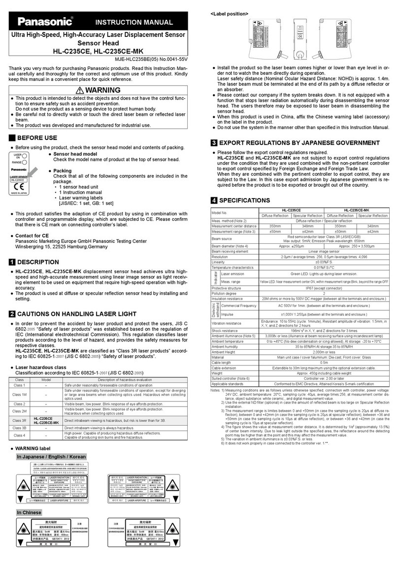
Panasonic HL-C235CE User manual

Panasonic

Panasonic HL-C235CE User manual

Panasonic 4318 Parts list manual

Panasonic

Panasonic 4318 Parts list manual

Panasonic SF4B-F31G(V2) User manual

Panasonic

Panasonic SF4B-F31G(V2) User manual

Panasonic EQ-30 Series User manual

Panasonic

Panasonic EQ-30 Series User manual

Panasonic HG-C Series User manual

Panasonic

Panasonic HG-C Series User manual

Panasonic GD Series User manual

Panasonic

Panasonic GD Series User manual

Panasonic GD-3 User manual

Panasonic

Panasonic GD-3 User manual

Panasonic KX-TGA20 User manual

Panasonic

Panasonic KX-TGA20 User manual

Panasonic WJ-HDB501 User manual

Panasonic

Panasonic WJ-HDB501 User manual

Panasonic HG-S Series User manual

Panasonic

Panasonic HG-S Series User manual

Panasonic FD-F41Y User manual

Panasonic

Panasonic FD-F41Y User manual

Panasonic SF4B V2 series User manual

Panasonic

Panasonic SF4B V2 series User manual

Panasonic KX-HNS104EX User manual

Panasonic

Panasonic KX-HNS104EX User manual

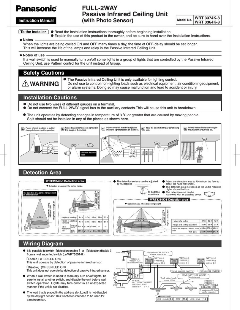
Panasonic WRT 3374K-8 User manual

Panasonic

Panasonic WRT 3374K-8 User manual

Panasonic Firetracker FT128 User manual

Panasonic

Panasonic Firetracker FT128 User manual

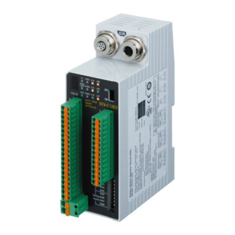
Panasonic ST4 Series User manual

Panasonic

Panasonic ST4 Series User manual

Panasonic GP-X SERIES User manual

Panasonic

Panasonic GP-X SERIES User manual

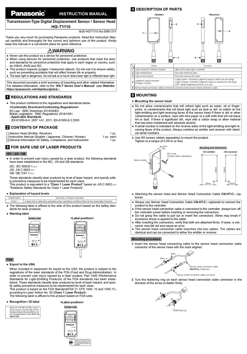
Panasonic HG-T1110 User manual

Panasonic

Panasonic HG-T1110 User manual

Panasonic HG-T1010 User manual

Panasonic

Panasonic HG-T1010 User manual

Panasonic SF4D-*-01 Series User manual

Panasonic

Panasonic SF4D-*-01 Series User manual

Panasonic SE4D Series User manual

Panasonic

Panasonic SE4D Series User manual

Panasonic SF4B-F23 V2 User manual

Panasonic

Panasonic SF4B-F23 V2 User manual

Popular Security Sensor manuals by other brands

Larson Electronics MS-AT-7A-LV instruction manual

Larson Electronics

Larson Electronics MS-AT-7A-LV instruction manual

Sensit HXG-3P instruction manual

Sensit

Sensit HXG-3P instruction manual

STEINEL PROFESSIONAL IR 180 COM1 Information

STEINEL PROFESSIONAL

STEINEL PROFESSIONAL IR 180 COM1 Information

System Sensor B210LP Installation and maintenance instructions

System Sensor

System Sensor B210LP Installation and maintenance instructions

Security-Center FU5125 installation guide

Security-Center

Security-Center FU5125 installation guide

AJAX FireProtect user manual

AJAX

AJAX FireProtect user manual

urmet domus 1051 quick guide

urmet domus

urmet domus 1051 quick guide

Bosch TriTech+ Professional ISC-PDL1-WAC30G installation instructions

Bosch

Bosch TriTech+ Professional ISC-PDL1-WAC30G installation instructions

PNI SafeHouse HS140 user manual

PNI

PNI SafeHouse HS140 user manual

Oceanic Systems 5302 installation instructions

Oceanic Systems

Oceanic Systems 5302 installation instructions

Teknim TFD-1271 Installation & user manual

Teknim

Teknim TFD-1271 Installation & user manual

Major tech MS361 instruction manual

Major tech

Major tech MS361 instruction manual

EnOcean EDK 350 user manual

EnOcean

EnOcean EDK 350 user manual

Dectris EIGER2 X 500K Technical specifications

Dectris

Dectris EIGER2 X 500K Technical specifications

Visonic K-980 installation instructions

Visonic

Visonic K-980 installation instructions

Forch 5380 16 1 manual

Forch

Forch 5380 16 1 manual

Distech Controls GS-AQOPM Series installation guide

Distech Controls

Distech Controls GS-AQOPM Series installation guide

Lithonia Lighting LVS Series Installation instruction supplement

Lithonia Lighting

Lithonia Lighting LVS Series Installation instruction supplement

manuals.online logo
manuals.online logoBrands
  • About & Mission
  • Contact us
  • Privacy Policy
  • Terms and Conditions

Copyright 2025 Manuals.Online. All Rights Reserved.