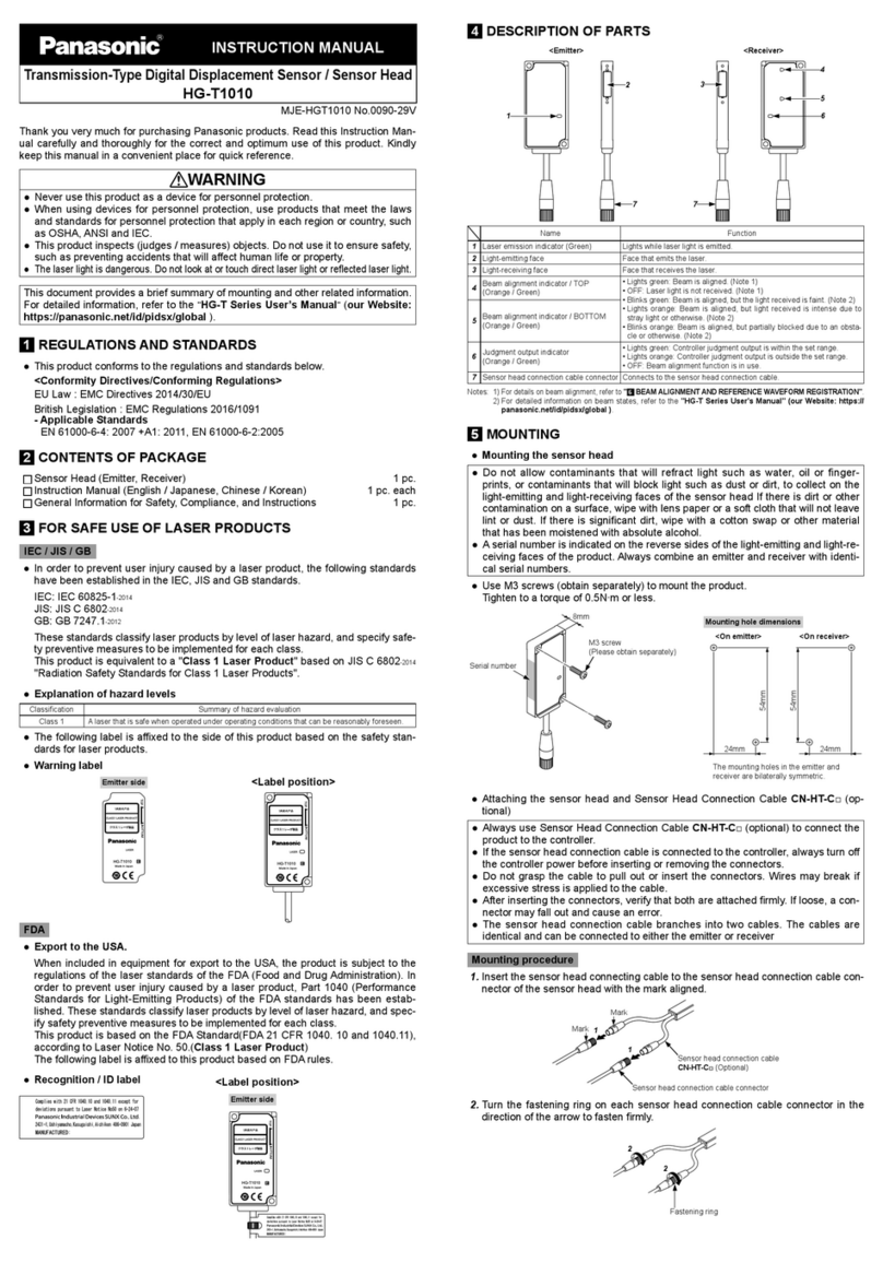
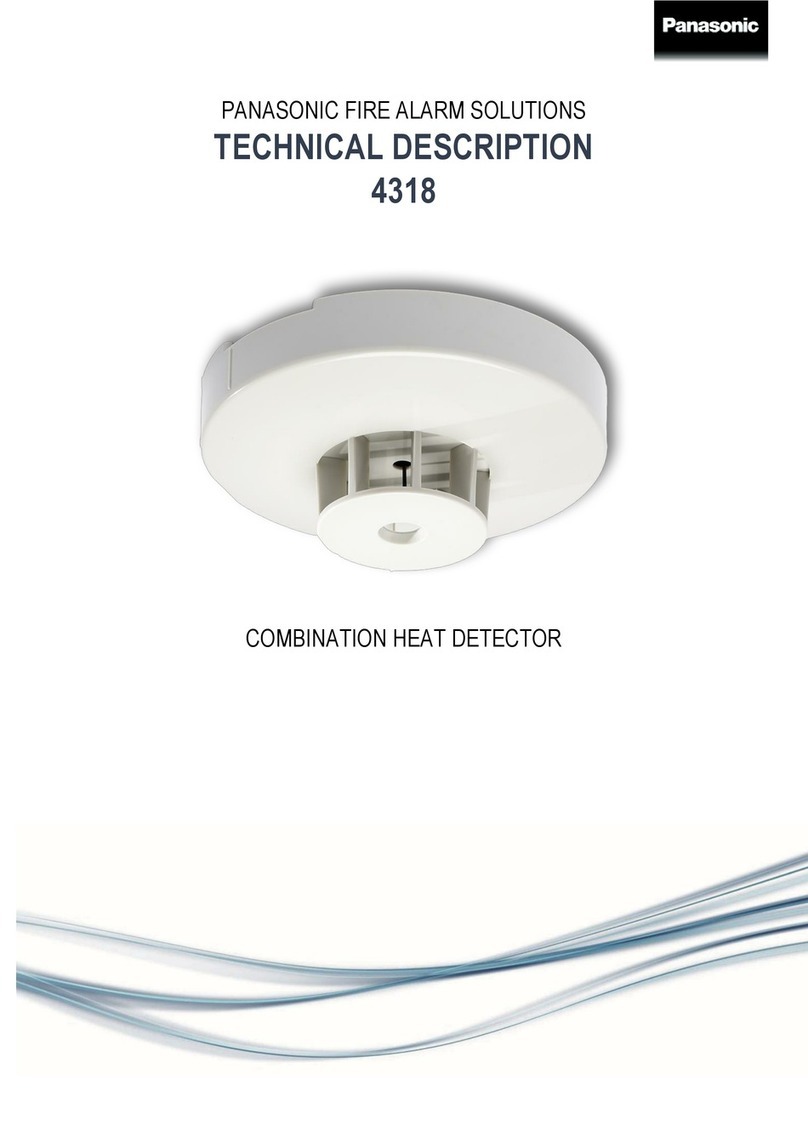
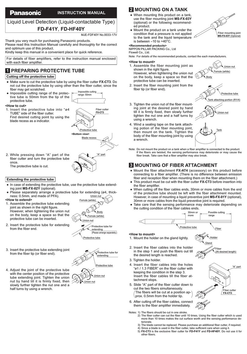
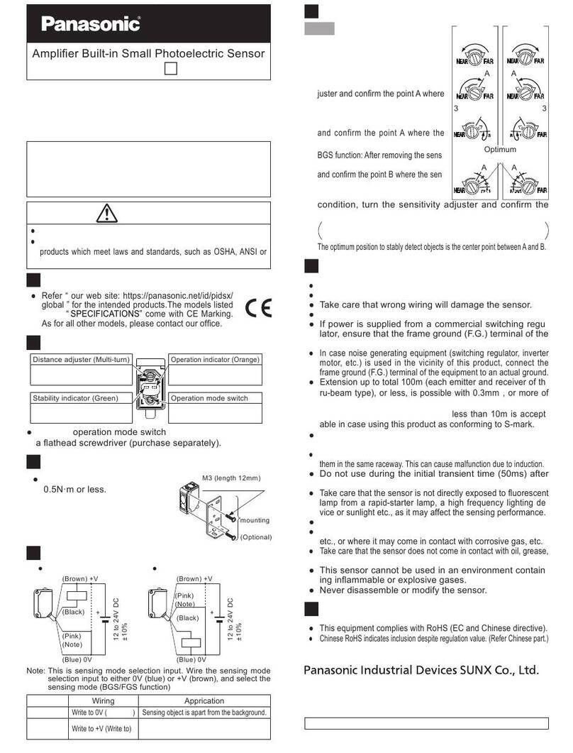
manuals.online logo
Brands
  1. Home
  2. •
  3. Brands
  4. •
  5. Panasonic
  6. •
  7. Security Sensor
  8. •
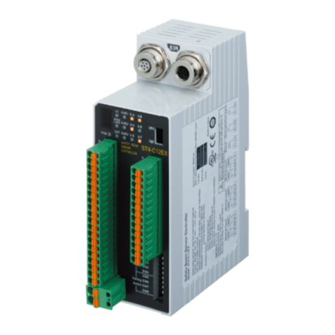
  9. Panasonic HG-C Series User manual

Panasonic HG-C Series User manual

INSTRUCTION MANUAL
Micro Laser Distance Sensor [CMOS]
HG-C Series
ME-HGC1000 No.0059-28V
Thank you very much for purchasing Panasonic products.
Please read this Instruction Manual carefully and thoroughly for the correct and opti-
mum use of this product.
Kindly keep this manual in a convenient place for quick reference.
WARNING
ƔThis product is for the sensing (determination and measurement) of objects. Do
not use this product to secure safety, such as accident prevention which may af-
fect human life and property.
ƔDo not stare directly into the laser beam, or through observation optical equip-
ment, such as lenses or etc. as it is dangerous.
1INTENDED PRODUCTS FOR CE MARKING
ƔThis product complies with the following standards / regulations.
<EU Directive>
EMC Directive
<Standards in US / Canada>
CAN/CSA-C22.2 NO. 60947-5-2-14
2CONFIRMATION OF PACKED CONTENTS
Sensor 1 pc.
Laser warning label (JIS Standards, GB Standard) 1 set each
)'$FHUWL¿FDWLRQODEHO SF
Instruction Manual (Japanese, English, Korean) 1 pc. each language
General Information for Safety, Compliance, and Instructions (23 languages) 1 pc.
3SAFE USE OF LASER PRODUCT
ƔFor the purpose of preventing any injury which may occur to the user by the use
of the laser product in advance, the following standards have been established by
the IEC Standards, JIS Standards, GB Standards and FDA Standards.
IEC : IEC 60825-1-2014
JIS : JIS C 6802-2014
GB : GB 7247.1-2012
FDA : PART 1040.10
7KHVHVWDQGDUGVFODVVL¿HVODVHUSURGXFWVDFFRUGLQJWRWKHOHYHORIKD]DUGDQG
provide the safety measures for respective classes.
ƔFDA Standards Outline
Requirements Class*1
I IIa II IIIa IIIb IV
Performance (all laser products)
Protective housing [1040.10 (f) (1)]
Safety interlocks [1040.10 (f) (2)]
Location of controls [1040.10 (f) (7)]
Viewing optics [1040.10 (f) (8)]
Scanning safeguards [1040.10 (f) (9)]
R*2
R*3,4
N/A
R
R
R*2
R*3,4
R
R
R
R*2
R*3,4
R
R
R
R*2
R*3,4
R
R
R
R*2
R*3,4
R
R
R
R*2
R*3,4
R
R
R
Performance (laser system)
Remote control connector [1040.10 (f) (3)]
Key control [1040.10 (f) (4)]
Emission indicator [1040.10 (f) (5)]
Beam attenuator [1040.10 (f) (6)]
Reset [1040.10 (f) (10)]
N/A
N/A
N/A
N/A
N/A
N/A
N/A
N/A
N/A
N/A
N/A
N/A
R
R
N/A
N/A
N/A
R
R
N/A
R
R
R*10
R
N/A
R
R
R*10
R
R*13
3HUIRUPDQFHVSHFL¿FSXUSRVHSURGXFWV
Medical [1040.11 (a)]
Measurement, leveling, alignment [1040.11 (b)]
Demonstration [1040.11 (c)]
S
S
S
S
S
S
S
S
S
S*8
S
S
S*8
NP
S*11
S*8
NP
S*11
Labeling (all laser products)
&HUWL¿FDWLRQLGHQWL¿FDWLRQ>@
Protective housing [1040.10 (g) (6), (7)]
Aperture [1040.10 (g) (4)]
Class warning [1040.10 (g) (1), (2), (3)]
R
D*5
N/A
N/A
R
R*5
N/A
R*6
R
R*5
R
R*7
R
R*5
R
R*9
R
R*5
R
R*12
R
R*5
R
R*12
Information (all laser products)
User information [1040.10 (h) (1)]
Product literature[1040.10 (h) (2) (i)]
Service information[1040.10 (h) (2) (ii)]
R
N/A
R
R
R
R
R
R
R
R
R
R
R
R
R
R
R
R
R : Required
N/A: Not applicable
S : Same as for other products of that Class. Also see footnotes.
NP : Not permitted
D : Depends on level of interior radiation.
*1 : Class is based on the maximum level of laser exposure during operation.
*2 :
Required wherever and whenever human access to laser radiation above Class I limits is not
needed for products to perform its functions.
*3 : Required for protective housings opened during operation or maintenance, if human access
thus gained is not always necessary when housing is opened.
*4 : The requirements for interlock differ depending on the class of inner radiation.
*5 : The contents of label differ depending on the level and wavelength of laser radiation inside
the protective housing.
*6 : Warning statement label.
*7 : CAUTION logotype.
*8 : The method to measure the level of laser radiation to human body is required.
*9 : CAUTION if 2.5mWcm-2 or less, DANGER is greater than 2.5mWcm-2
*10 : Delay required between indication and emission.
*11 : Exception should be provided for demonstration of laser products or light shows using laser
of Class IIIb or IV.
*12 : DANGER logotype.
*13 : Required after August 20, 1986.
ƔWARNING label
In Japanese In English
In Chinese
Ɣ)'$FHUWL¿FDWLRQODEHO
<Label position>
ƔAn English warning label is attached to this product. When this product is used
in Japan or China, peel off the English warning label, and attach the Japanese or
Chinese warning label.
Ɣ:KHQH[SRUWLQJWKLVSURGXFWWRWKH8QLWHG6WDWHRI$PHULFDDWWDFKWKH)'$FHUWL¿-
cation label to the cable close to the sensing device.
4PART DESCRIPTION
Output operation indicator (Orange)
Teaching indicator (Yellow)
Zero set indicator (Yellow)
Digital indicator (Red)
PRO indicator (Yellow)
Laser emission indicator (Green)
TEACH key UP key DOWN key
5MOUNTING
ƔWhen mounting this product, use M3 screws (prepare separately).
Use a tightening torque of 0.5N・m for mounting.
ƔWhen mounting this product using the sensor mounting bracket (optional), also
use a tightening torque of 0.5N・m.
M3 screws (prepare separately)
18mm
37mm
Mounting hole dimensions
Mounting Direction
ƔDirection to a movable body
<When there are differences in material and color>
• When performing measurements
of moving objects with exces-
sively different materials and
colors, mount the product per the
IROORZLQJGLUHFWLRQVWR PLQLPL]H
measurement errors.
<Measurement of rotating objects>
• When measuring rotating objects,
mount the product as follows.
Measurement can be performed
ZLWKPLQLPL]HGHIIHFWRQ WKHRE-
MHFWFDXVHG E\XSGRZQGHÀHF-
tion, position deviation and etc.
<When there is a step>
• When there is a step in the mov-
ing object, mount the product as
follows. Measurement can be
SHUIRUPHGZLWKPLQLPL]HGHIIHFW
from the edges of the steps.
ƔMeasuring of narrow locations and recesses
• When measuring in narrow loca-
tions or inside holes, mount the
product so that optical path from
the light emitting part to light-
receiving part is not interrupted.
Ramco Innovations
(
800
)
280-6933 www.panasonicsensors.com nsales
@
ramcoi.com
For amazing technical/application support or to place an order contact Ramco Innovations
ƔMounting the sensor to a wall
•
Mount the product as follows, so
that the multiple light reflections
on the wall do not emit to the light-
UHFHLYLQJSDUW:KHQWKHUHÀHFWLRQ
factor on a wall is high, it is effec-
tive to use a dull black color.
6I/O CIRCUIT DIAGRAMS
ƔNPN Output Type
Main circuit
AGND
(Brown) +V
(Pink) External input
(Black) Control output
(Blue) 0V
(Gray) Analog output
(Shield) Analog ground AGND
Load
External
input
Analog
input device
+
-
12 to 24V DC
±10%
ƔPNP Output Type
Main circuit
AGND
(Brown) +V
(Pink) External input
(Black) Control output
(Blue) 0V
(Gray) Analog output
(Shield) Analog ground AGND
Load
External
input
Analog
input device
+
-
12 to 24V DC
±10%
7TEACHING
2-point teaching
ƔThis is the basic teaching method.
12
Background Sensing object
Threshold
ON
OFF
Distance
1. Press the TEACH key in the background present condition.
2. Press the TEACH key in the sensing object present condition.
Stable sensing is possible
Stable sensing is not possible
Limit-teaching
ƔThis is teaching method in case small object or object in background are existing.
<When an object in background is used as reference>
UP key
Threshold
Teaching value
Distance
Background
<When a sensing object is used as reference>
DOWN key
Teaching value
Threshold
Distance
Sensing object
1. Press the TEACH key in the background present condition or the
sensing object present condition.
2. When an object in the background is used as a reference, press the
UP key to set the threshold on the sensor side.
When a sensing object is used as a reference, press the DOWN
key to set the threshold on the sensing object side.
3. Teaching is completed.
Automatic
1-point teaching (Window comparator mode)
ƔThis is mode is used for setting the threshold range for the distance from the ref-
erence value of the sensing object, by performing 1-point teaching. This mode is
used for sensing within the threshold range.
ƔWhen performing 1-point teaching (window comparator mode), preset “Window
comparator mode 1” in the sensing output setting of the PRO mode. For the set-
ting method, refer to “
12
PRO MODE SETTING.”
OFF
ON
OFF
Threshold 2_SL
Reference surface
Threshold 1_SL
Sensing object
1. Press the TEACH key twice in the sensing object present condition.
(1st time: TEACH mode, 2nd time: Teaching)
2. Teaching is completed.
Automatic
2-point teaching (Window comparator mode)
Ɣ
This is method to set the threshold range by conducting the 2-point teaching.
ƔWhen performing 2-point teaching (window comparator mode), preset “Window
comparator mode 2” in the sensing output setting of the PRO mode.
For the setting, refer to “
12
PRO MODE SETTING.”
ƔWhen conducting teaching, use sensing objects (P-1 and P-2) whose distance are
different from each other.
Sensing object P-1 Sensing object P-2
1st time (Threshold 1_SL)
2nd time (Threshold 2_SL)
OFF
OFF
ON
Distance
1. Press the TEACH key in the sensing object P-1 present condition. (1st time)
2. Press the TEACH key in the sensing object P-2 present condition. (2nd time)
Stable sensing is possible
Stable sensing is not possible
3-point teaching (Window comparator mode)
Ɣ
This is the method to perform 3-point teaching (P-1, P-2, P-3) and to set the threshold range
by setting threshold 1_SL in the mid-point between the 1st time and 2nd time, and threshold
B6/LQWKHPLGSRLQWEHWZHHQWKHQGWLPHDQGUGWLPHDVVKRZQLQWKHIROORZLQJ¿JXUH
ƔWhen performing 3-point teaching (window comparator mode), preset “Window
comparator mode 3” in the sensing output setting of the PRO mode.
For the setting, refer to “
12
PRO MODE SETTING.”
Ɣ
When performing teaching, use sensing objects (P-1, P-2, P-3) with different distance.
Ɣ
After teaching, P-1, P-2 and P-3 will be automatically rearranged from the smaller value.
Sensing object
P-1
Sensing object
P-2
Sensing object
P-3
1st time
2nd time
3rd time
Threshold1_SL
Threshold2_SL
OFF
OFF
ON
Distance
1. Press the TEACH key in the sensing object P-1 present condition. (1st time)
3. Press the TEACH key in the sensing object P-3 present condition. (3rd time)
2. Press the TEACH key in the sensing object P-2 present condition. (2nd time)
Stable sensing is possible
Stable sensing is not possible
Ramco Innovations
(
800
)
280-6933 www.panasonicsensors.com nsales
@
ramcoi.com
Span adjustment in rising differential mode or trailing differential mode
ƔThis mode is used to cancel the gradual changes in the measured value, and to
only detect sudden changes.
ƔWhen performing rising differential mode or trailing differential mode, preset “Ris-
ing differential mode” or “Trailing differential mode” in the sensing output setting of
the PRO mode. For the setting method, refer to “
12
PRO MODE SETTING.”
Ɣ7KHWKUHVKROGFDQEH VHW E\ XVLQJ WKHWKUHVKROGYDOXH¿QHDGMXVWPHQWIXQFWLRQ
)RUWKHWKUHVKROGYDOXH¿QHDGMXVWPHQWIXQFWLRQUHIHUWR³ 8THRESHOLD VAL-
UE FINE ADJUSTMENT FUNCTION.”
1. Press the TEACH key.
3. Press the TEACH key to set.
2. Press the UP key or DOWN key to select the span.
Short span Long span
8THRESHOLD VALUE FINE ADJUSTMENT FUNCTION
ƔFine adjustment of the threshold can be performed in the measurement display.
ƔFine adjustment of the threshold can be performed even after teaching.
<Normal sensing mode, rising differential mode or trailing differential mode>
Automatically
set after about 3
seconds.
Press the UP / DOWN key Press the UP / DOWN key Press the TEACH key
&RQ¿UPHG
<Window comparator mode>
ƔWhen the sensing output is set to window comparator mode, the display of
“” and “ ” can be changed by pressing the TEACH key for 1 second.
Change the thresh-
old value Measurement display
Press the TEACH
key for 1 second
Automatic
Ɣ:KHQSHUIRUPLQJD¿QHDGMXVWPHQWRIWKHWKUHVKROGRI³ ” or ”, press
the UP key or DOWN key. After “ ” or “ ´LVGLVSOD\HGWKH¿QHDGMXVW-
ment of the threshold can be performed.
(Automatically set after about 3 seconds.)
Press down UP /
DOWN key
Press down UP /
DOWN key
Press the TEACH
key
&RQ¿UPHG
Automatic
or
9PEAK / BOTTOM HOLD FUNCTION
Ɣ
The peak / bottom hold function, is for displaying the peak value and bottom value.
Ɣ:KHQWKH]HURVHWIXQFWLRQ LV H[HFXWHG ZKLOHWKHSHDNERWWRPKROGIXQFWLRQLV
set to “Peak hold” or “Bottom hold”, the held measured value will be reset.
Digital Display Description Function
Hold function
release
Releases the hold status,
and outputs the current
measured value
Peak hold
Holds maximum mea-
sured value
Bottom hold
Holds minimum measured
value
Press the TEACH key
and UP key simultane-
ously for 3 seconds. Press the TEACH key
Press down UP /
DOWN key
&RQ¿UPHGSelect
Automatically set after
about 3 seconds.
or
or
or
10
ZERO SET FUNCTION
Ɣ
7KH]HURVHWIXQFWLRQLVWKHIXQFWLRQWRFRPSXOVRULO\VHWWKHPHDVXUHGYDOXHWR³]HUR´
Ɣ7KH]HURVHWLQGLFDWRU\HOORZZLOOWXUQ21ZKHQWKH]HURVHWLVYDOLG
Ɣ:KHQWKH]HURVHWIXQFWLRQ LV H[HFXWHG ZKLOHWKHSHDNERWWRPKROGIXQFWLRQLV
valid, the held measured value will be reset.
Ɣ:KHQWKHGLVSOD\VHWWLQJLVVHWWR2IIVHWWKH]HURVHWIXQFWLRQFDQQRWEHVHW
<Zero set setting>
Press the UP key and DOWN key
simultaneously for 3 seconds.
&RQ¿UPHG
<Zero set release>
Press the UP key and DOWN key
simultaneously for 6 seconds.
Automatic
“ “ will be dis-
played during this
period.
Ɣ
7KHVHWWLQJRUUHOHDVLQJRIWKH]HURVHWIURPDQH[WHUQDOLQSXWRSHUDWHVDVLQWKHIROORZLQJ¿JXUH
Zero set setting Zero set release
10ms or more
1 sec.
Zero set valid period
OFF
ON
Ɣ:KHQWKHSRZHULVWXUQHG21DJDLQ]HURVHWIURPH[WHUQDOLQSXWFDQEHUHOHDVHG
$WWKLVWLPHWKH]HURVHWZLOOQRWEHVDYHG
Ɣ(YHQZKHQWKH]HURVHWLVVHWLQWKHVHQVRUWKH]HURVHWFDQEHVHWRUUHOHDVHG
IURPDQH[WHUQDOLQSXW+RZHYHUZKHQWKHSRZHULVWXUQHG21DJDLQWKH]HURVHW
set in the sensor will be displayed.
11
KEY LOCK FUNCTION
ƔThe key lock function is to prevent acceptance of key operations, so that the con-
ditions set in each setting mode are not changed accidentally.
ƔWhen key operation is performed after the key lock is set, “ ” will be displayed
on the digital display.
<Key lock setting>
Press the TEACH key and DOWN
key simultaneously for 3 seconds.
Automatic
<Key lock release>
Press the TEACH key and DOWN
key simultaneously for 3 seconds.
Automatic
12
PRO MODE SETTING
Part description
7($&+NH\&RQ¿UPHG
UP key (Select)
DOWN key (Select)
PRO indicator (Yellow)
$UURZGHVFULSWLRQLQ¿JXUHV
: Press UP key or DOWN key
: Press DOWN key
: Press the TEACH key
ƔThe PRO indicator (yellow) will turn ON when the PRO mode is set.
ƔWhen the DOWN key is pressed for 3 seconds or more in the middle of the PRO
MODE setting, the display returns to the measurement display.
Item Default setting Description
Response speed
setting
Set the response time.
“ ”: High precision 10ms, “ ”: Standard 5ms
“ ”: High speed 1.5ms
Output operation
setting
Select the control output operation mode.
“ ”: Light-ON, “ ”: Dark-ON
Sensing output
setting
Set the sensing output.
“ ”: Normal sensing mode
“ ”: 1-point teaching (Window comparator mode)
“ ”: 2-point teaching (Window comparator mode)
“ ”: 3-point teaching (Window comparator mode)
“ ”: Trailing differential mode
Analog output
setting
Sets the output operation of analog output setting.
“ ”: Analog voltage output (0 to +5V)
“ ”: Analog current output (4 to 20mA)
Hysteresis setting
<HG-C1030><HG-C1050>Set the hysteresis width.
HG-C1030: 0.001 to 5.00mm
HG-C1050: 0.01 to 15.00mm
HG-C1100: 0.02 to 35.00mm
HG-C1200: 0.1 to 80.0mm
HG-C1400: 0.2 to 200.0mm
<HG-C1100><HG-C1200>
<HG-C1400>
External input
setting
Set the external input.
“ ”: Zero set function, “ ”: Teaching function
“ ”: Light emitting stop function, “ ”: Trigger function
Timer setting
6HWWKHWLPHURSHUDWLRQ7KHWLPHUWLPHLV¿[HGDWPV
“ ”: No timer, “ ”: OFF-delay timer
“ ”: ON-delay timer, “ ”: One-shot timer
Display setting The display of the measured value can be changed.
“ ”: Normal, “ ”: Invert, “ ”: Offset
Hold setting
Set the control output and the analog output operation when a
PHDVXUHPHQWHUURURFFXUV LQVXI¿FLHQW OLJKWLQWHQVLW\VDWXUD-
tion of light intensity, out of measurement range).
“ ”: Hold OFF, “ ”: Hold ON
ECO Setting
The digital display can be set to go OFF when key operation is not
performed for 30 seconds. Current consumption can be reduced.
“ ”: ECO OFF, “ ”: ECO ON
Reset setting Return to the default setting (factory setting).
“ ”: Reset NG, “ ”: Reset OK
Ramco Innovations
(
800
)
280-6933 www.panasonicsensors.com nsales
@
ramcoi.com
Procedure
Sensing output
setting
External input
setting
Measurement display
DOWN: Press for 3 seconds
UP / DOWN
UP / DOWN
UP / DOWN
UP / DOWN
UP / DOWN
UP / DOWN
UP / DOWN
UP / DOWN
UP / DOWN
UP /
DOWN
UP /
DOWN
UP /
DOWN
UP /
DOWN
UP /
DOWN
UP /
DOWN
UP /
DOWN
UP /
DOWN
UP /
DOWN
TEACH
TEACH
TEACH
TEACH
TEACH
TEACH
TEACH
TEACH
TEACH
UP /
DOWN
UP /
DOWN
UP /
DOWN
UP /
DOWN
UP /
DOWN
UP /
DOWN
UP /
DOWN
UP /
DOWN
UP /
DOWN
Response time
setting
Response time
setting
Timer setting
Hysteresis setting
Output operation
setting
Reset setting
Hold setting
ECO Setting
High precision
No timer
Zero set function
Normal sensing
mode
Hysteresis width
UP key : Increases hysteresis width
DOWN key : Decreases hysteresis width
Light-ON
Reset NG
Hold OFF
ECO OFF
Standard
OFF-delay
Teaching function
Dark-ON
Reset OK
Hold ON
ECO ON
High speed
ON-delay
Light emitting
stop function
Rising differen-
tial mode
One-shot
Trigger function
Trailing differen-
tial mode
UP / DOWN
UP /
DOWN
TEACH
UP /
DOWN
Display setting Normal Invert Offset
1-point teaching
Window com-
parator mode
2-point teaching
Window com-
parator mode
3-point teaching
Window com-
parator mode
UP / DOWN
UP /
DOWN
TEACH
Analog output
setting
Analog voltage
output
Analog current
output
13
CAUTIONS
ƔThis product has been developed / produced for industrial use only.
ƔMake sure that the power supply is OFF before starting the wiring.
ƔIf the wiring is performed incorrectly, it will cause a failure.
ƔDo not run the wires together with high-voltage lines or power lines, or put them in
the same raceway. This can cause malfunction due to induction.
ƔVerify that the supply voltage variation is within the rating.
ƔIf power is supplied from a commercial switching regulator, ensure that the frame
ground (F.G.) terminal of the power supply is connected to an actual ground.
ƔIf noise generating devices (switching regulators, inverter motors, etc.) are used
around the sensor mounting area, make sure to connect the frame ground (FG)
terminal of the device.
Ɣ
Do not use this product during the transient state when the power supply is turned ON.
ƔThe overall length of the cable can be extended to 10m maximum with a cable
VL]HRIPP2or more.
Ɣ
Make sure that stress by forcible bend or pulling is not applied to the sensor cable joint.
ƔAlthough it depends on the type, light from rapid start type or high frequency
OLJKWLQJW\SHÀXRUHVFHQWOLJKWVVXQOLJKWDQGHWFPD\DIIHFWWKHVHQVLQJWKHUHIRUH
make sure to prevent direct incident light.
ƔThis product is suitable for indoor use only.
Ɣ
.HHSZDWHURLO¿QJHUSULQWVDQGHWFZKLFKUHÀHFWOLJKWRUGXVWSDUWLFOHVRUHWFZKLFKLQ-
terrupts the light, away from the emitting / receiving surfaces of this product. If contami-
nants adhere to the surface, wipe off with a dust-free soft cloth, or lens cleaning paper.
ƔDo not use the sensor in locations where there is excessive vapor, dust or etc. or
in an atmosphere where corrosive gases, etc. is generated.
ƔTake care that the product does not come in contact with oil, grease, organic sol-
vents such as thinner, etc., strong acid or alkaline.
ƔMake sure to turn OFF the power supply, before cleaning the light emitting / re-
ceiving windows of the sensor head.
ƔThere is a certain deviation in the directionality of this product. Install the product
XVLQJDPRXQWLQJEUDFNHWRUVLPLODU¿WWLQJWRDOORZWKHDGMXVWPHQWRIRSWLFDOD[LV
ƔThe internal memory (nonvolatile) of this product has a service life. Settings can-
QRWEHFRQ¿JXUHGPRUHWKDQWLPHV
14
ERROR INDICATION
ƔIn case of errors, attempt the following measures.
Error indication Description Remedy
<Hold OFF>
<Hold ON>
Measured value blinks
,QVXI¿FLHQWDPRXQWRIUHÀHFWHGOLJKW
The sensing object is out of the sensing range.
&RQ¿UPWKDWWKHVHQVLQJGLVWDQFHLVZLWKLQWKH
VSHFL¿FDWLRQUDQJH
Adjust the installation angle of the sensor.
Flash memory is damaged or passed its life expectancy.
3OHDVHFRQWDFWRXURI¿FH
Load of the sensing output is short-circuited
FDXVLQJDQRYHUFXUUHQWWRÀRZ Turn OFF the power and check the load.
The semiconductor laser is damaged or
passed its life expectancy. 3OHDVHFRQWDFWRXURI¿FH
• :KHQ]HURVHW LV VHWWKH PHDVXUHPHQW LV
not performed normally.
• Since the display setting is set to “Offset”,
WKH]HURVHWIXQFWLRQFDQQRWEHXVHG
• &RQ¿UPWKDWWKHVHQVLQJGLVWDQFHLVZLWKLQ
WKHVSHFL¿FDWLRQUDQJH
•
Set the display to any setting except “Offset.”
During teaching, the measurement is not per-
formed normally.
&RQ¿UPWKDWWKHVHQVLQJGLVWDQFHLVZLWKLQWKH
VSHFL¿FDWLRQUDQJH
System error 3OHDVHFRQWDFWRXURI¿FH
15
SPECIFICATIONS
Type
Measurement
center 30mm type
Measurement
center 50mm type
Measurement cen-
ter 100mm type
Measurement cen-
ter 200mm type
Measurement cen-
ter 400mm type
Model No. NPN output HG-C1030 HG-C1050 HG-C1100 HG-C1200 HG-C1400
PNP output HG-C1030-P HG-C1050-P HG-C1100-P HG-C1200-P HG-C1400-P
Measurement center
distance 30mm 50mm 100mm 200mm 400mm
Measurement range ±5mm ±15mm ±35mm ±80mm ±200mm
Repeatability ȝP ȝP ȝP ȝP
ȝPPHDVXUHPHQW
distance 200 to 400mm)
ȝPPHDVXUHPHQW
distance 400 to 600mm)
Linearity ±0.1%F.S. ±0.2%F.S.
±0.2%F.S. (measurement
distance 200 to 400mm)
±0.3%F.S. (measurement
distance 400 to 600mm)
Temperature characteristic 0.03%F.S./°C
Light source Red semiconductor laser Class 2 [JIS / IEC / GB / FDA (Note 2)]
Max. output: 1mW, Emission peak wavelength: 655nm
Beam diameter (Note 3) Approx.
¡ȝP
Approx.
¡ȝP
Approx.
¡ȝP
Approx.
¡ȝP
Approx.
¡ȝP
Supply voltage 12 to 24V DC ±10%, Ripple P-P 10% or less
Power consumption 40mA or less (at 24V DC supply voltage), 65mA or less (at 12V DC supply voltage)
Control output
<NPN output type>
NPN open-collector transistor
• Maximum sink current: 50mA
• Applied voltage: 30V DC or less
(Between control output to 0V)
• Residual voltage: 1.5V or less
(At 50mA sink current)
• Leakage current: 0.1 mA or less
<PNP output type>
PNP open-collector transistor
• Maximum source current: 50mA
• Applied voltage: 30V DC or less
(Between control output to +V)
• Residual voltage: 1.5V or less
(At 50mA source current)
• Leakage current: 0.1 mA or less
Output operation Switchable either Light-ON or Dark-ON
Short-circuit protection Incorporated (Auto reset type)
Analog output
Analog voltage
output
• Output range: 0 to +5V (at alarm: +5.2V)
• 2XWSXWLPSHGDQFHȍ
Analog current
output
• Output range: 4 to 20mA (at alarm: 0mA)
• /RDGLPSHGDQFHȍRUOHVV
Response time Switchable between 1.5ms / 5ms / 10ms
External input
<NPN output type>
NPN non-contact input
• Input conditions
Invalid: +8 to +V DC or Open
Valid: 0 to +1.2V DC
• ,QSXWLPSHGDQFH$SSUR[Nȍ
<PNP output type>
PNP non-contact input
• Input conditions
Invalid: 0 to +0.6V DC or Open
Valid: +4 to +V DC
• ,QSXWLPSHGDQFH$SSUR[Nȍ
Protection IP67 (IEC)
Degree of pollution 2
Ambient temperature -10 to +45°C (No dew condensation or icing allowed), Storage: -20 to +60°C
Ambient humidity 35 to 85% RH, Storage: 35 to 85% RH
Ambient illuminance ,QFDQGHVFHQWODPS$FFHSWDQFHVXUIDFHLOOXPLQDQFHƐ[RUOHVV
Operating altitude 2,000m or less
Cable 0.2mm25-core composite cable, 2m long
Material Enclosure: Aluminum die-cast, Front cover: Acrylic
Weight Approx. 35g (without cable), approx. 85g (including cable)
Notes: 1)
Supply voltage: 24V DC, ambient temperature: +20°C, response time: 10ms, and analog output value of mea-
VXUHPHQWFHQWHUGLVWDQFHDUHXVHGIRUXQVSHFL¿HGPHDVXUHPHQWFRQGLWLRQV7KHVXEMHFWLVZKLWHFHUDPLFV
2) This is based on the FDA Standard, according to Laser Notice No. 50 of the FDA Standard.
3)
7KLVLVWKHVL]HLQWKHPHDVXUHPHQWFHQWHUGLVWDQFH7KHVHYDOXHVZHUHGH¿QHGE\XVLQJH
2
(approx. 13.5%)
RIWKHFHQWHUOLJKWLQWHQVLW\'XH WR OHDNOLJKWRXWVLGHWKHVSHFL¿HG DUHD WKHUHÀHFWDQFHDURXQGWKHGHWHFWLQJ
point may be higher than at the point and this may affect the measurement value.
http://panasonic.net/id/pidsx/global
2YHUVHDV6DOHV'LYLVLRQ+HDG2I¿FH
2431-1 Ushiyama-cho, Kasugai-shi, Aichi, 486-0901, Japan
Phone: +81-568-33-7861 FAX: +81-568-33-8591
For sales network, please visit our website.
PRINTED IN CHINA © Panasonic Industrial Devices SUNX Co., Ltd. 2017
Ramco Innovations
(
800
)
280-6933 www.panasonicsensors.com nsales
@
ramcoi.com

Other Panasonic Security Sensor manuals

Panasonic SE4D Series User manual

Panasonic

Panasonic SE4D Series User manual

Panasonic HG-T1010 User manual

Panasonic

Panasonic HG-T1010 User manual

Panasonic CX-44 Series User manual

Panasonic

Panasonic CX-44 Series User manual

Panasonic SF4B V2 series User manual

Panasonic

Panasonic SF4B V2 series User manual

Panasonic HG-T1110 User manual

Panasonic

Panasonic HG-T1110 User manual

Panasonic HG-S Series User manual

Panasonic

Panasonic HG-S Series User manual

Panasonic HL-C235CE User manual

Panasonic

Panasonic HL-C235CE User manual

Panasonic GD Series User manual

Panasonic

Panasonic GD Series User manual

Panasonic WRT 3374K-8 User manual

Panasonic

Panasonic WRT 3374K-8 User manual

Panasonic SF4-AH Series User manual

Panasonic

Panasonic SF4-AH Series User manual

Panasonic GD-3 User manual

Panasonic

Panasonic GD-3 User manual

Panasonic HG-S Series User manual

Panasonic

Panasonic HG-S Series User manual

Panasonic SF4D-*-01 Series User manual

Panasonic

Panasonic SF4D-*-01 Series User manual

Panasonic ST4 Series User manual

Panasonic

Panasonic ST4 Series User manual

Panasonic BM-ET330E User guide

Panasonic

Panasonic BM-ET330E User guide

Panasonic Firetracker FT128 User manual

Panasonic

Panasonic Firetracker FT128 User manual

Panasonic GP-X SERIES User manual

Panasonic

Panasonic GP-X SERIES User manual

Panasonic HG-F13A-A-N User manual

Panasonic

Panasonic HG-F13A-A-N User manual

Panasonic 6295 User manual

Panasonic

Panasonic 6295 User manual

Panasonic SF4B-F31G(V2) User manual

Panasonic

Panasonic SF4B-F31G(V2) User manual

Panasonic SF4B-H G-01 Series User manual

Panasonic

Panasonic SF4B-H G-01 Series User manual

Panasonic KX-HNS104EX User manual

Panasonic

Panasonic KX-HNS104EX User manual

Panasonic EQ-30 Series User manual

Panasonic

Panasonic EQ-30 Series User manual

Panasonic HL-G1 Series User manual

Panasonic

Panasonic HL-G1 Series User manual

Popular Security Sensor manuals by other brands

Larson Electronics MS-AT-7A-LV instruction manual

Larson Electronics

Larson Electronics MS-AT-7A-LV instruction manual

Sensit HXG-3P instruction manual

Sensit

Sensit HXG-3P instruction manual

STEINEL PROFESSIONAL IR 180 COM1 Information

STEINEL PROFESSIONAL

STEINEL PROFESSIONAL IR 180 COM1 Information

System Sensor B210LP Installation and maintenance instructions

System Sensor

System Sensor B210LP Installation and maintenance instructions

Security-Center FU5125 installation guide

Security-Center

Security-Center FU5125 installation guide

AJAX FireProtect user manual

AJAX

AJAX FireProtect user manual

urmet domus 1051 quick guide

urmet domus

urmet domus 1051 quick guide

Bosch TriTech+ Professional ISC-PDL1-WAC30G installation instructions

Bosch

Bosch TriTech+ Professional ISC-PDL1-WAC30G installation instructions

PNI SafeHouse HS140 user manual

PNI

PNI SafeHouse HS140 user manual

Oceanic Systems 5302 installation instructions

Oceanic Systems

Oceanic Systems 5302 installation instructions

Teknim TFD-1271 Installation & user manual

Teknim

Teknim TFD-1271 Installation & user manual

Major tech MS361 instruction manual

Major tech

Major tech MS361 instruction manual

EnOcean EDK 350 user manual

EnOcean

EnOcean EDK 350 user manual

Dectris EIGER2 X 500K Technical specifications

Dectris

Dectris EIGER2 X 500K Technical specifications

Visonic K-980 installation instructions

Visonic

Visonic K-980 installation instructions

Forch 5380 16 1 manual

Forch

Forch 5380 16 1 manual

Distech Controls GS-AQOPM Series installation guide

Distech Controls

Distech Controls GS-AQOPM Series installation guide

Lithonia Lighting LVS Series Installation instruction supplement

Lithonia Lighting

Lithonia Lighting LVS Series Installation instruction supplement

manuals.online logo
manuals.online logoBrands
  • About & Mission
  • Contact us
  • Privacy Policy
  • Terms and Conditions

Copyright 2025 Manuals.Online. All Rights Reserved.